In the article “How to determine the roof load in your area,” we decided on the classic version gable roof. But very often there are situations when awnings are attached to a house, and not everyone knows that these awnings will be loaded with snow much more than the roof itself. When collecting snow loads, there is such a thing as a snow bag. If there are differences in height on the roof, or the canopy is simply adjacent to a high wall, then favorable conditions to make a snowdrift in this place. And the higher the wall to which the roof adjoins, the greater the height of this snowdrift will be, and the greater the load will affect bearing structures. Sometimes a snow bag can increase the standard snow load several times.
Let's look at the situation using an example.
House with gable roof. A canopy is attached to it on both sides. It is necessary to determine the snow load per 1 m 2 of the roof of the house and two canopies. Construction area – Kiev region (160 kg/m2).
1) Let's determine the snow load on the roof of the house.
Roof angle 35 degrees. Let's open diagram 1 of Appendix Zh DBN V.1.2-2:2006 “Loads and impacts”.

Because the angle of inclination of the roof does not fit into the range of 20-30 degrees, and there are no bridges with lanterns, then we need to take the load diagram according to option 1 - the same for the entire roof.
By interpolation we determine:
S e = γ fe S 0 C = 0,49*160*0,71 = 55,7 kg/m2;
γfe
S 0
WITH = μC e C alt = 0.71*1*1 = 0.71 – according to clause 8.6 of the DBN.
S m = γ fm S 0 C = 1.14*160*0,71 = 129.5 kg/m2;
γ fm= 1.14 – according to Table 8.1 of the DBN “Loads and Impacts”, subject to the service life of the house being 100 years (specified by the customer),
S 0 = 160 kg/m2 – according to the initial data,
WITH = μC e C alt = 0.29*1*1 = 0.71 – according to clause 8.6 of the DBN.

2) Let us determine the snow load on the canopy located along the long (12-meter) side of the building.
Let's open diagram 8 of Appendix Zh DBN V.1.2-2:2006 “Loads and impacts”.

Because We have a canopy, not a veranda with walls, we need to go with option “b”.
h= 1 m > S 0 /2 h μ need to be determined. (Otherwise, one coefficient μ 1 would apply for the entire canopy).
Let's determine the coefficient μ for our case:
μ = 1 + (m 1 L 1 " + m 2 L 2 " )/h = 1 + (0.3*9 + 0.19*2)/1 = 4,08,
wherein μ = 4,08 < 6 (для навесов) и μ = 4,08 > 2h/ S 0 μ = 1.25.
m 1 = 0.3 – for flat covering houses with a slope of more than 20 degrees;
m 2 = 0,5k 1 k 2 k 3 = 0.5*0.46*0.83*1 = 0.19 (with the length of the canopy along the house a < 21 м);
k 1 = √A/21 = √4.5/21 = 0.46 (here A
k 2 = 1 – β /35 = 1 – 6/35 = 0.83 (here β – canopy slope angle);
k 3 = 1 – φ /30 = 1 – 0/30 = 1 > 0.3 (here φ
L 1 " = L 1 = 9 m – in the absence of lights;
L 2 " = L 2
h
μ = 4,08 > 2 h/ S 0 = 2*1/1.6 = 1.25 (here μ b according to the formula:
b = 2h(μ – 1 + 2m 2 )/(2h/ S 0 – 1 + 2m 2 ) = 2*1(4.08 – 1 + 2*0.19)/(2*1/1.6 – 1 + 2*0.19) = 11 m< 16 м.
Because b= 11 m > 5 h b= 5 m.
Let's compare the values:
b= 5 m > L 2
Let's determine the coefficient μ 1:
μ 1= 1 – 2m 2 = 1 – 2*0,19 = 0,62.
The operational snow load per 1 m 2 of the horizontal projection of the roof of the house is determined by formula 8.2:
S e = γ fe S 0 C = 0,49*160*1,25 = 98 kg/m2;
S e 1 = γ fe S 0 C 1 = 0,49*160*0,62 = 48,6 kg/m2;
γfe= 0.49 – according to table 8.3 DBN “Loads and impacts”,
S 0 = 160 kg/m2 – according to the initial data,
WITH = μC e C alt =
C 1 = μ 1 C e C alt = 0.62*1*1 = 0.62 – according to clause 8.6 of the DBN.
The maximum design value of the load per 1 m 2 of the horizontal projection of the roof of the house is determined by formula 8.1:
S m = γ fm S 0 C = 1.14*160*1,25 = 228 kg/m2;
S m 1 = γ fm S 0 C 1 = 1.14*160*0,62 = 113 kg/m2;
γ fm

3) Let's determine the snow load on the canopy located along the short (9-meter) side of the building.
For this canopy, due to the shape of the pediment, the difference is h will be different, so the snow load will be variable not only across, but also along the canopy.
a. Let's find the snow load values for the maximum drop height h = 4.5 m.
Let's check whether it is necessary to take into account the local load at the drop (here and below the value of S 0 is taken in kPa):
h= 4.5 m > S 0 /2 h= 1.6/(2*4.5) = 0.17 m – local load must be taken into account, coefficient μ need to be determined.
Let's determine the coefficient μ :
μ = 1 + (m 1 L 1 " + m 2 L 2 " )/h = 1 + (0.4*12 + 0.25*2)/4,5 = 2,18,
wherein μ = 2,18 < 6 (для навесов) и μ = 2,18 < 2h/ S 0 = 2*4.5/1.6 = 5.6 – we finally accept μ = 2,18.
m 1 = 0.4 – for a flat roof on a house with a slope of less than 20 degrees (the roof has no slope in this direction);
m 2 = 0,5k 1 k 2 k 3 a < 21 м);
k 1 = √A/21 = √7.5/21 = 0.6 (here A– length of the canopy along the building);
k 2 = 1 – β /35 = 1 – 6/35 = 0.83 (here β – canopy slope angle);
k 3 = 1 – φ /30 = 1 – 0/30 = 1 > 0.3 (here φ – the slope angle of the canopy along the house, it can be seen in option “c” of diagram 8).
L 1 " = L 1
L 2 " = L 2 = 2 m – in the absence of lights;
h= 4.5 m – the difference between the roof and the canopy.
Let's find the length of the zone of increased snow deposits. Let's check the condition:
μ = 2,18 < 2 h/ S 0 = 2*4.5/1.6 = 5.6, then we find b according to the formula:
b = 2h= 2*4.5= 9 m< 16 м.
Let's compare the values:
b= 9 m > L 2 = 2 m – the calculation is carried out according to option 2 of scheme 8.
Let's determine the coefficient μ 1:
μ 1= 1 – 2 m 2 = 1 – 2*0,25 = 0,5.
The operational snow load per 1 m 2 of the horizontal projection of the roof of the house is determined by formula 8.2:
S e = γ fe S 0 C = 0,49*160*2,18 = 171 kg/m2;
S e 1 = γ fe S 0 C 1 = 0,49*160*0,5 = 39,2 kg/m2;
γfe= 0.49 – according to table 8.3 DBN “Loads and impacts”,
S 0 = 160 kg/m2 – according to the initial data,
WITH = μC e C alt = 2.18*1*1 = 2.18 – according to clause 8.6 of the DBN,
C 1 = μ 1 C e C alt =
The maximum design value of the load per 1 m 2 of the horizontal projection of the roof of the house is determined by formula 8.1:
S m = γ fm S 0 C = 1.14*160*2,18 = 398 kg/m2;
S m 1 = γ fm S 0 C 1 = 1.14*160*0,5 = 91,2 kg/m2;
γ fm= 1.14 – according to Table 8.1 of the DBN “Loads and Impacts”, subject to the service life of the house being 100 years (specified by the customer).
b. Let's find the snow load values for the minimum drop height h = 1.0 m.
Let's check whether it is necessary to take into account the local load at the drop (here and below the value of S 0 is taken in kPa):
h= 1 m > S 0 /2 h= 1.6/(2*1) = 0.8 m – it is necessary to take into account the local load, coefficient μ need to be determined.
Let's determine the coefficient μ for our case:
μ = 1 + (m 1 L 1 " + m 2 L 2 " )/h = 1 + (0.4*12 + 0.25*2)/1 = 6,3,
wherein μ = 6.3 > 6 (for awnings) and μ = 6.3 > 2h/ S 0 = 2*1/1.6 = 1.25 – we finally accept μ = 1.25.
m 1 = 0.4 – for a flat roof on a house with a slope of less than 20 degrees (in this direction the roof slope is zero);
m 2 = 0,5k 1 k 2 k 3 = 0.5*0.6*0.83*1 = 0.25 (with the length of the canopy along the house a < 21 м);
k 1 = √A/21 = √7.5/21 = 0.6 (here A– length of the canopy along the building);
k 2 = 1 – β /35 = 1 – 6/35 = 0.83 (here β – canopy slope angle);
k 3 = 1 – φ /30 = 1 – 0/30 = 1 > 0.3 (here φ – the slope angle of the canopy along the house, it can be seen in option “c” of diagram 8).
L 1 " = L 1 = 12 m – in the absence of lights;
L 2 " = L 2 = 2 m – in the absence of lights;
h= 1 m – the difference between the roof and the canopy.
Let's find the length of the zone of increased snow deposits. Let's check the condition:
μ = 6.3 > 2 h/ S 0 = 2*1/1.6 = 1.25 (here μ we take what was found in the calculation, and not what was finally accepted), then we find b according to the formula:
b = 2h(μ – 1 + 2m 2 )/(2h/ S 0 – 1 + 2m 2 ) = 2*1(6.3 – 1 + 2*0.25)/(2*1/1.6 – 1 + 2*0.25) = 15.5 m< 16 м.
Because b= 15.5 m > 5 h= 5*1 = 5 m, final acceptance b= 5 m.
Let's compare the values:
b= 5 m > L 2 = 2 m – the calculation is carried out according to option 2 of scheme 8.
Let's determine the coefficient μ 1:
μ 1= 1 – 2 m 2 = 1 – 2*0,25 = 0,5.
The operational snow load per 1 m 2 of the horizontal projection of the roof of the house is determined by formula 8.2:
S e = γ fe S 0 C = 0,49*160*1,25 = 98 kg/m2;
S e 1 = γ fe S 0 C 1 = 0,49*160*0,5 = 39,2 kg/m2;
γfe= 0.49 – according to table 8.3 DBN “Loads and impacts”,
S 0 = 160 kg/m2 – according to the initial data,
WITH = μC e C alt = 1.25*1*1 = 1.25 – according to clause 8.6 of the DBN,
C 1 = μ 1 C e C alt = 0.5*1*1 = 0.5 – according to clause 8.6 of the DBN.
The maximum design value of the load per 1 m 2 of the horizontal projection of the roof of the house is determined by formula 8.1:
S m = γ fm S 0 C = 1.14*160*1,25 = 228 kg/m2;
S m 1 = γ fm S 0 C 1 = 1.14*160*0,5 = 91,2 kg/m2;
γ fm= 1.14 – according to Table 8.1 of the DBN “Loads and Impacts”, subject to the service life of the house being 100 years (specified by the customer).

So, if we compare the results for the three parts of the example, we get the following:

The figure graphically shows the relationship between the projections of operational snow loads for a house and two sheds. For a house, the lowest snow load is 55.7 kg/m2 (shown in blue). For the first canopy (along the 12-meter wall of the house), a huge “snowdrift” is already obtained, the load from which is 98 kg/m2 at the wall of the house and 48.6 kg/m2 at the edge of the canopy (shown in pink). For the second shed, located at the high gable of the house (along the 9-meter wall of the house), the situation has worsened significantly: the snowdrift reaches maximum sizes near the wall in the area of the highest point of the ridge and gives a load of 170 kg/m2, then its “height” drops towards the edges of the house to 98 kg/m2 on one side and to 122 kg/m2 on the other (we find it by interpolation), and towards the edge of the canopy the load decreases to 39.2 kg/m2 (shown in green).
Please note that the figure does not show the dimensions of the “drifts”, but the magnitude of the load that the swept snowdrifts will give. It is important.
As a result, our analysis showed by example that attached canopies carry the risk of significant overload of structures, especially those adjacent to high vertical wall Houses.
Finally, I will give one piece of advice: in order to minimize the load on a canopy attached to a wall parallel to the ridge of the house, you need to use the condition from diagram 8 of Appendix G to the DBN “Loads and Impacts” (we checked this condition at the very beginning of the calculation):
If in our example the height of the difference was not 1 m, but 0.7 m, then the following condition would be met:
h= 0.7 m< S 0 /2 h= 1.6/(2*0.7) = 1.14 m - and as written in paragraph 3, the local load at the drop no longer needs to be taken into account. What does this mean? When the local load needs to be taken into account, near the drop the snow load is determined with the coefficient μ , and at the edge of the canopy - with a significantly lower coefficient μ 1. If the local load does not need to be taken into account, then the load on the entire canopy is determined with the coefficient μ 1. In our example, the ratio μ/ μ 1= 1.25/0.62 = 2, i.e. By raising the canopy by 30 cm, we can reduce the snow load on it by half.
In this article, examples were calculated according to Ukrainian standards (DBN “Loads and Impacts”). If you calculate according to other standards, check the coefficients; otherwise, the snow load schemes of DBN and SNiP are the same.
Metal trusses for a canopy are one of the most basic structures. They are often erected on summer cottages and territories country houses. This simple designs from frame, covering and additional elements. You can use them to make a canopy that covers the space allocated for storing things, or to create a mini parking lot for a car. You can do the entire assembly yourself, but to make the truss strong and durable, correct calculations are necessary.
Sheds are designed to provide space for storing things or constructing a mini parking lot for a car.
Types of structures
Trusses are made from rectangular profiles or metal corners. The material is selected depending on the type of structure and type of belts. The belts are the basis of the farm; they are located below and above the structure and form its spatial outline. For the manufacture of small structures, profile pipes are used.
Farms have several forms:
- Polygonal. This type of trusses is designed for installation on spans of 10 meters or more in length. If you install the canopy on small area, then the structure is equipped with additional parts, which complicates its assembly. Canopies manufactured in production and having an arched shape are an exception.
- Triangular. This is a gable canopy with a slope of 22-30 degrees. It is often installed in regions where there is a large amount of snowfall. The disadvantage of the product is the sharp knot at the base of the structure and the long supports located in the center. These areas must be correctly calculated and marked on the drawing. Polycarbonate trusses for canopies of small sizes have proportions in relation to height and width of no more than ¼, 1/5.

There are many types of frame trusses, they differ in the complexity of construction and have a different number of advantages
- Parallel. According to the drawing, the slope of the finished product is no more than 1.5%. In this case, the ratio of height and length varies from 1/6 to 1/8. The product is used for a flat canopy, which is planned to be finished with roll cladding. The belt rods that create the spatial lattice have a uniform length, which results in a minimum of connecting nodes.
- Arched. This is the most convenient farm design. It allows you to hide bending lines in the cross sections of the frame. In addition, the arch material experiences constant compression. Therefore, all calculations are carried out according to a simplified template, since the weight from the roof, installation lathing and the snow load will be equally distributed throughout the canopy.
- Trapezoidal. The tilt angle of the frame ranges from 6 to 150 degrees. Moreover, its height and length have proportions of 1/6. The product is characterized by a rigid frame.
- The entire load acts on the supports of the structure and is directed downward. Because of this, it is evenly distributed. Consequently, the support pillars have good resistance against compression. This allows you to withstand the additional weight from snow cover.
- Since the arches are less rigid, the load is distributed unevenly. Because of this, under the influence of load they unbend. As a result, a force appears that acts on the supports located at the top of the structure.
- The length of the frame must exactly match the length of the span (the interval overlapping the profile).
- Depending on the developed angle and characteristics of the outline, the height of the structure is determined. If the structure is triangular, then its height varies from 1/5 or ¼ of the length. The ratio of straight roofing is 1/8.
- The angle of inclination of the grille to the belt varies from 35 to 50 degrees. The average value is 45 degrees.
- The width of the panel will help you correctly calculate the gap between the nodes. They are always identical. If the frame has longer length span (25-30 meters or more), then it requires a construction lift. It is calculated additionally. These calculations will help determine the load level and select the appropriate value profile pipes.
- So that the building has a beautiful appearance and at the same time withstand high loads, the distance between the arches is 105 cm. In this case, the height of the structure will be 150 cm.
- The sector length formula π × R × α ÷ 180 will help calculate the length of the profile along the lower chord. According to the drawing: R = 410 cm, α ÷ 160°. Substituting the numbers, it turns out: 3.14 × 410 × 160 ÷ 180 = 758 (cm).
- The frame nodes are placed on the lower belt. The distance between them must be at least 55 cm. An individual calculation is required to install the extreme units.
This video shows how to draw a truss drawing for a canopy:
What level of load the structure can withstand depends on the thickness of the profile pipe. The thicker it is, the stronger the structure. For large structures, it is better to choose a square profile with a cross-section of 30-50×30-50 mm. Pipes with a smaller cross-section are used for a small frame.
Metallic profile has high strength and compared to a solid metal bar it weighs much less. The material bends easily, this allows you to create arched and dome-shaped structures.
Ready-made metal profile canopy trusses have affordable price. To ensure that the material lasts a long time, it is painted or coated with a primer, which will protect it from corrosion.
Polycarbonate truss
To assemble a truss for a polycarbonate canopy, you need to make detailed diagram. Each part indicated in the diagram must have exact dimensions. Details from complex design drawn in an additional drawing.
To select the type of structure and the number of component parts, it is necessary to make calculations. Additionally study the level atmospheric precipitation in your region. This data will help create a structure of the required strength. The most simplified type of truss is an arc (pipe) with a round or square cross-section. Despite the fact that this is the most cheap option Of all, polycarbonate pipes are not very reliable.
Load distribution:
Incorrect calculation of a truss for a canopy threatens that the bases of the pillars will become bent and deformed.
When calculating a polycarbonate truss, the height and length of the frame are taken into account, as well as the angle of inclination of the lattice and the distance between the modules. Calculation example:
For example, the calculation for a single-pitched frame measuring 4 × 6 m is as follows. The structure is created from a 3x3 cm profile. Its thickness is 0.12 cm. The length of the lower belt is 310 cm, and the upper one is 390 cm. Vertical supports are mounted between the belts. The height of the largest will be 60 cm, the other three will be shortened evenly. After installing the supports, there are places that need to be strengthened. They are equipped with slanting lintels (thin profile with a cross-section of 2×2 cm). In places where the belts are connected, racks are not installed.
If the canopy is long (6-7 meters), then 5 such structures are installed. They are placed at a distance of 1.5 m. Each module is secured with transverse jumpers. A profile with a cross section of 2×2 cm is used as jumpers.
It is placed at a distance of 50 cm from each other and secured to the upper belt. The polycarbonate sheathing is attached to the lintels.
Arch frame
Due to its special structure, an arched truss for a canopy also requires precise calculations. They are necessary to ensure that the acting load is distributed evenly over the entire surface. And this is only possible thanks to the correct and even shape of the frame.
Making an arched frame 6 meters long:
-
Canopies are classified as the most simple structures, which are being built on a suburban or summer cottage. They are used for a variety of purposes: as a parking lot, storage area and many other options.
Structurally, the canopy is extremely simple. This
- frame, the main element of which is trusses for canopies, which are responsible for the stability and strength of the structure;
- coating. It is made of slate, polycarbonate, glass or corrugated sheet;
- additional elements. As a rule, these are decoration elements that are located inside the structure.
The design is quite simple, and it also weighs little, so you can assemble it with your own hands right on the site.
However, in order to get a practical, correct canopy, you first need to ensure its strength and long-term operation. To do this, you should know how to calculate a truss for a canopy, make it yourself and weld it or buy ready-made ones.
Metal trusses for canopies

This design consists of two belts. The upper and lower chords are connected through braces and vertical racks. It is able to withstand significant loads. One such product, weighing from 50–100 kg, can replace metal beams three times larger in weight. With proper calculation, the metal truss in, channels or does not deform or bend when exposed to loads.
A metal frame experiences several loads at the same time, which is why it is so important to know how to calculate a metal truss in order to accurately find the equilibrium points. This is the only way the structure can withstand even very high impacts.
How to choose material and cook them correctly

Creation and self installation canopies are possible with small dimensions of the structure. Trusses for canopies, depending on the configuration of the belts, can be made of profiles or steel angles. For relatively small structures, it is recommended to choose profile pipes.
Such a solution has a number of advantages:
- The load-bearing capacity of a profile pipe is directly related to its thickness. Most often, to assemble the frame, a material with a square cross-section of 30-50x30-50 mm is used, and for small structures, pipes of a smaller cross-section are suitable.
- For metal pipes They are characterized by greater strength and yet they weigh much less than a solid metal bar.
- Pipes are bent - a quality necessary when creating curved structures, for example, arched or domed.
- The price of trusses for sheds is relatively small, so buying them will not be difficult.
On a note
The metal frame will last much longer if it is protected from corrosion: treated with a primer and painted.
- On such metal carcass You can conveniently and quite simply lay almost any sheathing and roofing.
Methods for connecting profiles
How to weld a canopy
Among the main advantages of profile pipes, the non-shaped connection should be noted. Thanks to this technology, a truss for spans not exceeding 30 meters is structurally simple and relatively inexpensive. If its upper belt is sufficiently rigid, then the roofing material can be supported directly on it.
Unshaped welded joint has a number of advantages:
- The weight of the product is significantly reduced. For comparison, we note that riveted structures weigh 20%, and bolted structures weigh 25% more.
- Reduces labor and manufacturing costs.
- welding cost is low. Moreover, the process can be automated if you use devices that allow uninterrupted feeding of welded wire.
- the resulting seam and the attached parts are equally strong.
One of the disadvantages is the need to have experience in welding.
Bolt-on mounting
Bolted connections of profile pipes are not used very rarely. It is mainly used for collapsible structures.
The main advantages of this type of connection include:
- Simple assembly;
- No need for additional equipment;
- Possible dismantling.
But at the same time:
- The weight of the product increases.
- Additional fasteners will be required.
- Bolted connections less durable and reliable than welded ones.

How to calculate a metal truss for a canopy made from a profile pipe

The structures being erected must be rigid and strong enough to withstand various loads, therefore, before installing them, it is necessary to calculate a truss from a profile pipe for a canopy and draw up a drawing.
When calculating, as a rule, they resort to the help of specialized programs taking into account the requirements of SNiP (“Loads, impacts”, “ Steel structures"). You can calculate a metal truss online using the metal profile canopy calculator. If you have the appropriate engineering knowledge, you can carry out the calculation yourself.
On a note
If the main design parameters are known, you can search for a suitable ready-made project among those posted on the Internet.

Design work is carried out on the basis of the following initial:
- Drawing. The configuration of the frame belts depends on the type of roof: single or gable, hip or arched. The most simple solution can be considered a single-pitched truss made from a profile pipe.
- Design dimensions. The larger the trusses are installed, the greater the load they can withstand. The angle of inclination is also important: the greater it is, the easier it will be to remove snow from the roof. For the calculation, you will need data on the extreme points of the slope and their distance from each other.
- Element sizes roofing material. They play a crucial role in determining the pitch of the trusses for a canopy, say. By the way, this is the most popular coating for structures built on their own plots. They bend easily, so they are suitable for constructing curved coverings, for example, arched ones. All that matters is how to do it right calculate a polycarbonate canopy.
The calculation of a metal truss from a profile pipe for a canopy is performed in a certain sequence:
- determine the span corresponding to the technical specifications;
- to calculate the height of the structure, substitute the span dimensions according to the presented drawing;
- set the slope. According to the optimal shape of the roof of the structure, the contours of the belts are determined.
On a note
The maximum possible pitch of trusses for a canopy when using a profile pipe is 175 cm.
How to make a polycarbonate truss

The first stage of making your own trusses from a profile pipe for a canopy is to draw up a detailed plan, which should indicate the exact dimensions of each element. In addition, it is advisable to prepare additional drawing structurally complex parts.
As you can see, before you make trusses yourself, you need to be well prepared. Let us note once again that while when choosing the shape of a product they are guided by aesthetic considerations, to determine structural type and the number of constituent elements, a design path is required. When testing for strength metal structure It is also necessary to take into account data on atmospheric loads in a given region.
The arc is considered an extremely simplified variation of the truss. This is one profiled pipe with a round or square cross-section.
Obviously, this is not only the simplest solution, it is also cheaper. However, polycarbonate canopy poles have certain disadvantages. In particular, this concerns their reliability.

arched canopies photos
Let's analyze how the load is distributed in each of these options. The design of the truss ensures uniform distribution of the load, that is, the force acting on the supports will be directed, one might say, strictly downward. This means that the support pillars perfectly resist compression forces, that is, they can withstand the additional pressure of the snow cover.
The arches do not have such rigidity and are not able to distribute the load. To compensate for this kind of impact, they begin to unbend. The result is a force placed on the supports at the top. If we take into account that it is applied to the center and directed horizontally, then the slightest error in calculating the base of the pillars will, at the very least, cause their irreversible deformation.
An example of calculating a metal truss from a profile pipe
The calculation of such a product assumes:
- definition exact height(H) and length (L) of the metal structure. The latter value must exactly correspond to the span length, that is, the distance overlapping the structure. As for the height, it depends on the designed angle and contour features.
In triangular metal structures, the height is 1/5 or ¼ of the length, for other types with straight belts, for example, parallel or polygonal - 1/8.
- The angle of the grid braces ranges from 35–50°. On average it is 45°.
- It is important to determine optimal distance from one node to another. Usually the required gap coincides with the width of the panel. For structures with a span length of more than 30 m, it is necessary to additionally calculate the construction lift. In the process of solving the problem, you can obtain the exact load on the metal structure and select correct parameters profile pipes.

As an example, consider the calculation of trusses for a standard 4x6 m lean-to structure.
The design uses a 3 by 3 cm profile, the walls of which are 1.2 mm thick.
The lower belt of the product has a length of 3.1 m, and the upper one – 3.90 m. Between them, vertical posts made of the same profile pipe are installed. The largest of them has a height of 0.60 m. The rest are cut out in descending order. You can limit yourself to three racks, placing them from the beginning of the high slope.

The areas that are formed in this case are strengthened by installing diagonal lintels. The latter are made of a thinner profile. For example, a pipe with a cross section of 20 by 20 mm is suitable for these purposes. At the point where the belts meet, stands are not needed. On one product you can limit yourself to seven braces.
Five similar structures are used per 6 m length of the canopy. They are laid in increments of 1.5 m, connected by additional transverse jumpers made from a profile with a section of 20 by 20 mm. They are fixed to the upper chord, arranged in increments of 0.5 m. The polycarbonate panels are attached directly to these jumpers.
Calculation of an arched truss

The manufacture of arched trusses also requires precise calculations. This is due to the fact that the load placed on them will be distributed evenly only if the created arc-shaped elements have ideal geometry, that is, the correct shape.
Let's take a closer look at how to create an arched frame for a canopy with a span of 6 m (L). We will take the distance between the arches to be 1.05 m. With a product height of 1.5 meters, the architectural structure will look aesthetically pleasing and will be able to withstand high loads.
When calculating the profile length (mн) in the lower belt, use the following formula for the sector length: π R α:180, where the parameter values for this example in accordance with the drawing are equal respectively: R= 410 cm, α÷160°.

After substitution we have:
3.14 410 160:180 = 758 (cm).
The structural units should be located on the lower chord at a distance of 0.55 m (rounded) from each other. The position of the extremes is calculated individually.
In cases where the span length is less than 6 m, welding of complex metal structures is often replaced by a single or double beam, bending the metal profile to a given radius. Although there is no need to calculate the arched frame, however correct selection profiled pipe still remains relevant. After all, the strength of the finished structure depends on its cross-section.
Calculation of an arched truss from a profile pipe online
How to calculate the arc length for a polycarbonate canopy
 The arc length of an arch can be determined using Huygens' formula. The middle is marked on the arc, designated by point M, which is located on the perpendicular CM drawn to the chord AB, through its middle C. Then you need to measure the chords AB and AM.
The arc length is determined by the Huygens formula: p = 2l x 1/3 x (2l – L), where l is the chord AM, L is the chord AB)
The relative error of the formula is 0.5% if the arc AB contains 60 degrees, and as the angular measure decreases, the error drops significantly. For an arc of 45 degrees. it is only 0.02%.
A canopy is a simple architectural structure that is used for a variety of purposes. In most cases, it is made in the absence of a garage with a cover in the country or in order to protect the recreation area from the strong rays of the sun. To ensure the reliability and strength of such a small-sized building, you will need to calculate the canopy. Eventually it will be possible to obtain data that can show which farms will be used and how they will need to be brewed.
The diagram for fastening profile pipes can be seen in Fig. 1.
Figure 1 shows a diagram of pipe fastening
How to calculate trusses for a canopy with your own hands?
In order to calculate such a structure for a canopy, you will need to prepare:
- Calculator and special software;
- SNiP 2.01.07-85 and SNiP P-23-81.
When performing calculations, you will need to perform the following steps:
- First of all, you will need to select a farm layout. For this purpose, future contours are determined. The outline must be selected based on the main functions of the canopy, material and other parameters;
- After this, it will be necessary to determine the dimensions of the structure being manufactured. The height will depend on the type of roof and material used, weight and other parameters;
- If the span exceeds 36 m, you will need to make calculations for the construction lift. IN in this case this means reverse extinguishable bending from loads on the truss;
- It is necessary to determine the dimensions of the building panels, which must correspond to the distances between the individual elements that ensure the transfer of loads;
- At the next stage, the distance between the nodes is determined, which is most often equal to the width of the panel.
When making calculations, follow these tips:
- You will need to calculate all the values exactly. You should know that even the slightest defect will lead to errors in the process of carrying out all the work on the manufacture of the structure. If you are not sure about own strength, then it is recommended to immediately contact professionals who have experience in carrying out such calculations;
- To make your work easier you can use finished projects, into which all that remains is to substitute the existing values.
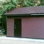
 This photo shows a metal shelter
 In the process of calculating the truss, it should be remembered that if its height increases, the load bearing capacity. IN winter time snow will practically not accumulate on such a canopy throughout the year. In order to increase the strength of the structure, several strong stiffeners should be installed.
To build a farm, it is best to use an iron pipe, which is light in weight, high in strength and rigidity. In the process of determining the dimensions for such an element, you will need to take into account the following data:
- For small structures, the width of which is up to 4.5 m, you will need to use a metal pipe 40x20x2 mm;
- For structures whose width is less than 5.5 m, you need to use a pipe with dimensions of 40x40x2 mm;
- If the width of the truss is more than 5.5 m, it is best to use a pipe 60x30x2 mm or 40x40x3 mm.
When planning the pitch of the trusses, it should be taken into account that the maximum possible distance between the pipes of the canopy is 1.7 m. Only in this case will it be possible to preserve the reliability and strength of the structure.
An example of calculating trusses for a canopy
- As an example, we will consider a 9 m wide canopy with a slope of 8°. The span of the structure is 4.7 m. Snow loads for the region are at the level of 84 kg/m²;
- The weight of the truss is approximately 150 kg (you should take a small margin for strength). Vertical load is 1.1 t per rack with a height of 2.2 m;
- One end of the truss will rest on the wall of a brick building, and the other on a column to support the canopy using anchor bolts. Used to make a truss square pipe 45x4 mm. It should be noted that such a device is quite convenient to work with;
- It is best to make trusses with parallel chords. The height of each element is 40 cm. A pipe with a cross-section of 25x3 mm is used for braces. A 35x4 mm pipe is used for the lower and upper chords. The visors and other elements will need to be welded to each other, so the wall thickness will be 4 mm.
Ultimately, you will be able to obtain the following data:
- Design resistance for steel: Ry = 2.45 T/cm²;
- Reliability factor - 1;
- Span for the farm - 4.7 m;
- Farm height - 0.4 m;
- The number of panels for the upper chord of the structure is 7;
- The corners will need to be cooked one at a time.
All necessary data for calculations can be found in special reference books. However, professionals recommend making calculations of this type using software. If a mistake is made, the manufactured trusses will collapse under the influence of snow and wind loads.
How to calculate a truss for a polycarbonate canopy?
The canopy is a complex structure, so before purchasing a certain amount of material you will need an estimate. The support frame must be able to withstand any load.
In order to make a professional calculation of a polycarbonate structure, it is recommended to seek help from an engineer with experience in such work. If the canopy is separate design, and not an extension to a private house, then the calculations will become more complicated.
Street roofing consists of posts, joists, trusses and covering. It is these elements that will need to be calculated.
If you plan to make an arched polycarbonate canopy, you cannot do without using trusses. Trusses are devices that connect joists and support posts. The size of the canopy will depend on such elements.
Canopies made of polycarbonate, the basis of which is used metal trusses, is quite difficult to manufacture. Correct frame will be able to distribute the load across the supporting posts and joists, while the canopy structure will not collapse.
For polycarbonate installation, it is best to use profile pipes. The main calculation of a truss is taking into account the material and slope. For example, for a single-pitched hanging structure applied with a slight slope irregular shape farms. If the structure has a small angle, then metal trusses in the shape of a trapezoid can be used. The larger the radius of the arch structure, the less possibility of snow retention on the roof. In this case, the load-bearing capacity of the farm will be high (Fig. 2).
 Figure 2 shows a future canopy covered with polycarbonate
 If you use a simple farm with a house measuring 6x8 m, then the calculations will be as follows:
- The step between the pillars for support is 3 m;
- Number of metal posts - 8 pcs;
- The height of the trusses under the slings is 0.6 m;
- To install the roof sheathing you will need 12 profile pipes with dimensions 40x20x0.2 cm.
In some cases, savings can be made by reducing the amount of material. For example, instead of 8 racks, you can install 6. You can also shorten the frame sheathing. However, it is not recommended to allow a loss of rigidity, as this can lead to the destruction of the structure.
Detailed calculation of the truss and arc for the canopy
In this case, a calculation will be made of the canopy, the trusses of which are installed in increments of 1 m. The load on such elements from the sheathing is transferred exclusively at the nodes of the truss. Corrugated sheeting is used as a roofing material. The height of the truss and arc can be any. If this is a canopy that is adjacent to the main building, then the main limiter is the shape of the roof. In most cases, it will not be possible to make the farm height more than 1 m. Taking into account the fact that you will need to make crossbars between the columns, maximum height will be 0.8 m.
A diagram of the canopy by truss can be seen in Fig. 3. Blue the sheathing beams are indicated; in blue is the truss that will need to be calculated. Violet color the beams or trusses on which the columns will rest are indicated.
In this case, 6 triangular trusses will be used. The load on the outer elements will be several times less than on the rest. In this case, the metal trusses will be cantilever, that is, their supports are located not at the ends of the trusses, but in the nodes shown in Fig. 3. This scheme allows you to evenly distribute the load.
 Figure 3 shows a shelter diagram for farms
 The design load is Q = 190 kg, while the snow load is 180 kg/m². Thanks to the sections, it is possible to calculate the forces in all the rods of the structure, while taking into account the fact that the truss and the load on this element are symmetrical. Consequently, it will be necessary to calculate not all trusses and arcs, but only some of them. In order to freely navigate a large number of rods during the calculation process, the rods and nodes are marked.
Formulas that you will need to use when calculating
It will be necessary to determine the forces in several truss rods. To do this, use the static equilibrium equation. The nodes of the elements have hinges, therefore the value of bending moments at the nodes of the truss is 0. The sum of all forces relative to the x and y axis is also 0.
You will need to create an equation of moments with respect to point 3 (e):
M3 = -Ql/2 + N2-a*h = 0, where l is the distance from point 3 to the point of application of force Q/2, which is 1.5 m, and h is the arm of the force N2-a.
The truss has a design height of 0.8 m and a length of 10 m. In this case, the tangent of the angle a will be tga = 0.8/5 = 0.16. Angle value a = arctga = 9.09°. Ultimately h = lsina. From this follows the equation:
N2-a = Ql/(2lsina) = 190/(2*0.158) = 601.32 kg.
In the same way, the value of N1-a can be determined. To do this, you will need to create an equation of moments with respect to point 2:
M2 = -Ql/2 + N1-a*h = 0;
N1-a = Q/(2tga) = 190/(2*0.16) = 593.77 kg.
You can check the correctness of the calculations by drawing up the equation of forces:
EQy = Q/2 - N2-asina = 0; Q/2 = 95 = 601.32 * 0.158 = 95 kg;
EQx = N2-acosa - N1-a = 0; N1-a = 593.77 = 601.32 * 0.987 = 593.77 kg.
The conditions of statistical equilibrium are met. Any of the force equations used in the testing process can be used to determine the forces in the members. Further calculations of trusses are carried out in the same way; the equations will not change.
It is worth knowing that the design scheme can be drawn up so that all longitudinal forces are directed from the cross sections. In this case, the “-” sign in front of the force indicator, which was obtained in the calculations, will show that such a rod will work in compression.
In order to determine the force in rod, you will first need to determine the value of the angle y: h = 3siny = 2.544 m.
A do-it-yourself canopy truss is easy to calculate. You just need to know the basic formulas and be able to use them.
Polycarbonate is an ideal material for It allows you to get a lightweight structure with a transparent roof through which sunlight penetrates. As a rule, the frame is made of profiled pipes. In order for the entire structure to be durable, it is necessary to correctly calculate
What does the frame consist of?
Before you start calculating a canopy, you need to clearly understand what elements it consists of. And there are only a few of them.
The racks, as the name suggests, are the elements on which the entire canopy rests. As a rule, it is 2.2-2.8 meters high. Its height depends on the method of fastening. If it is attached with anchors to a mortgage concreted in the ground, then its height is taken to be 2.2 meters. In cases where the stand is concreted or buried, the height is taken to be 2.8 meters.
Arches and trusses are used to strengthen the canopy. The latter are most often installed in two. And here exact amount arches can only be determined by a calculation of the canopy. This value depends on the dimensions of the structure.
A truss is a structural element that connects logs.
Polycarbonate sheets are attached to structural elements called guides. Thermal washers are used for this. Their location and step frequency depend on the distance between the supporting supports and (its thickness).
Stages of canopy installation
In order to correctly calculate a canopy from a profile pipe, it is useful to understand the entire process as a whole. It consists of several stages. Arches are attached to fixed posts. In this case, the angle between them should be exactly ninety degrees. The resulting sections are attached to the embedded anchors. Trusses are attached to the same supports. The angle between the trusses and the arches is also straight (that is, ninety degrees). The final stage of frame manufacturing is fixing the guides. They are attached to the top of the arches. At this point the frame is ready. After painting it, you can attach polycarbonate sheets.
Construction errors that should be taken into account when calculating
The construction of sheds is often carried out with errors. They affect not only the choice of the type of structure, but also the calculations carried out as a result
A common mistake is choosing a sloping awning. Often the structure is built on two pillars and tilted to the windward side. This is far from the most the best option for permanent use (for example, for parking a car). Danger awaits if the wind changes direction. The canopy in this case can be compared to an airplane wing. A lifting force is generated between it and the ground, which can easily tear down the canopy. Even if there are four pillars, this will not always save you.

Sloping awnings are suitable for situations where the structure is attached to a building. Free-standing inclined awnings must be made with curves. Moreover, the convex part is oriented “toward” the wind.
Types of canopies
Depending on the supporting elements, there are several types of canopies:
- Standing separately. They have vertical supports installed around the entire perimeter.
- Beam-supported, which are attached to the building on one side. They have one side supported by support pillars. The second one rests on a beam attached to the wall of the building.

- Cantilever-supported. They differ from the previous type in that here brackets or mortgages are attached to the wall.
- Cantilever ones, which are held entirely by mortgages. Usually these are small canopies over the door.
The calculation of the canopy of each type is carried out according to different schemes.
Types of awnings
According to their design, hanging structures can be of three types:
- Mono-pitched, in which the roof is inclined to one side.
- Gable with two directions of slope.
- Arched, in which the roof is made in the shape of a semicircle (arc).
Data collection
Calculation of a canopy from a profile pipe must begin with the collection necessary information. It should include the following data:
- Characteristics of the material.
- Purpose of the structure.
- Design form.
- Data on wind and snow loads (they are presented in special tables for each specific region).

The canopy calculation is carried out taking into account the information described above. It includes formulas and calculations. Not everyone can understand them. The best option is to use special programs and calculators. Today there are plenty of them on the Internet.
Canopies over the entrance cantilevered
Cantilever-type canopies depend on the size of the porch. According to requirements regulatory documents, the area in front of the door should be one and a half times the width of the door. The average door width is 0.9 meters. It turns out that minimum size the upper platform is 1.35 m (0.9 x 1.5 = 1.35). This value is equivalent to the recommended canopy depth.
As for the width of the visor, everything is simple here. It is made 0.6 meters larger than the width of the door. The visor should protrude 0.3 meters on each side.
Awnings are calculated in this simple way. Calculation of the structure with standard values leads to the following result: depth - 0.9-1.35 m, width - 1.4-1.8 m.
Cantilever-supported canopies over the door
These types of canopies are installed over the entire platform, covering the steps. Calculation of the depth of the canopy over the site is calculated similarly to the previous option. A part located above the steps is added to it. It directly depends on their quantity. For each step, about 0.25-0.32 m is added.
The width depends on the width of the stairs, on both sides of which 0.3 meters are added. If the standard width of the steps in front of the door is 0.8-1.2 meters, then we get the width of the canopy 1.1-1.5 meters.
Consider an option with a staircase of three steps and a platform standard sizes. The depth will be about 1.65-2.31 meters (0.9 + 3 x 0.25 or 1.35 + 3 x 0.32). The width under the same conditions is 1.4-1.8 meters. It is calculated as follows: 0.8 + 0.3 + 0.3 or 1.2 + 0.3 + 0.3. Two calculation options consider the minimum and maximum values of standard parameters.
Sheds adjacent to the building
Calculation lean-to canopy, which is adjacent to the house on one side, is carried out with minus half vertical supports. Another important point: sheet joints must be above the profile. This means that a distance of 1260, 2050 or 2100 millimeters must be maintained between the profiles, corresponding to the size of the polycarbonate sheet. The average canopy width is three meters. With this size there is enough space even for a car. Polycarbonate at this width will sag. He needs a rafter system.
First, the material is calculated. A canopy attached to a house with this size will have six vertical risers. They will all be located on one side. If the structure is free-standing, then twice as many supports are needed (that is, twelve, six on each side). For each rafter leg support is installed.
Single-pitch free-standing shed
The calculation of a free-standing structure must take into account the load carried by precipitation. The design will be as rigid as possible if it is made in the shape of a triangle.

The canopy calculation is carried out taking into account conventionally accepted values. At 2.1 x 0.6 m, the roof width is taken to be six meters and the length is 10.6 meters. Most best option: slope height 2.4 meters and 11 rafter sections. In such a situation, six profiles (standard length of six meters) will be required. Instead of eleven, you can make only two triangles. This will reduce the amount of materials used. This option is suitable for regions with average rainfall.
Calculation of a gable canopy
The calculation principle is similar to lean-to structures. The main thing is to achieve rigidity of the structure. And this is done using the same triangles. Their optimal quantity is calculated as follows. Every linear meter the canopy is divided vertical profile. The resulting rectangle is divided into two triangles.
Calculation of arched structures
Arched canopies are the most complex structures. The need for material is directly dependent on the convexity of the roof. This means that the steeper the convexity, the more materials will have to be spent.

In this case, you can save only on rafter system. With the previously discussed canopy dimensions (10.6 x 6 meters), two or three systems will be sufficient (two at the edges, one in the middle). The remaining “legs” will be arcs. It is not necessary to connect their ends. The metal profile used to make the truss is quite durable. It will be enough to provide the necessary rigidity. The main thing is that the truss is firmly attached to the risers.
If you make an arched canopy with these dimensions (for example, for a car), you will need the following materials:
Six profiles, curved in the shape of an arc, with a length of six meters. The ends of three of them are connected by a jumper. It is also recommended to divide them into several triangles to increase the rigidity of the structure.
For each arch you need two supports (under each edge). That is, a total of twelve of them are needed (2 x 6).
Along the edges, along the pillars and along the roof, longitudinal beams are attached. In total you will need six of them.
Calculation of main structural elements
The calculation of the pipe cross-section for a canopy depends on the height of the structure itself and the number of columns. If the size of the structure does not exceed five meters, the pipe is selected with a cross-section of 6-8 centimeters. At large sizes the number of risers should be increased. To avoid this, you can choose a profile with a large cross-section. For example, 10 centimeters.
The size of the sheathing will depend on the thickness of the polycarbonate and the size of the canopy. If a sheet of plastic is one centimeter thick, and the canopy measures 6 x 8 meters, then the sheathing will be assembled in increments of one meter. These values are in accordance with the loads. For this, there are special tables that take into account the load and the thickness of the polycarbonate. An example of this table can be seen in the photo below. It is designed for polycarbonate with thicknesses of six, eight, ten and sixteen millimeters.

Calculating an arched canopy involves calculating the trusses and their number. It is the dimensions of the trusses that determine the width of the entire canopy. To determine them, you need to know the following information:
- Farm dimensions.
- Material size (polycarbonate).
- Metal resistance.
- Method of fastening elements (welding, bolting, etc.).
- Load values (in accordance with regulatory documents).
- Steel structures according to SNiP.
The size of the canopy is chosen according to the size of the materials. If a polycarbonate sheet is six meters long, then it is either used entirely or cut into two parts. Of course, you can cut it into more pieces. But this will lead to waste generation. Thus, the roof will be either six meters or three meters high. Any length can be chosen, depending on personal preference.