Which defines him operational properties. Therefore, when constructing important load-bearing structures, builders carefully monitor this indicator. The most common method of control is to determine the strength of concrete by the peeling method. However, there are many other ways.
Therefore, in this article we will look in detail at how to determine the strength of concrete using the most common modern methods.
Types of strength testing methods
The most reliable way to control the quality of concrete is to test the concrete structure after the material has reached its design strength.
As for the testing of separately made control samples, it allows one to determine only, but not the strength of the material in the structure. This is due to the impossibility of ensuring the same conditions for the development of strength of the prototype (vibration, heating, etc.) and the concrete product.
All existing methods controls are divided into three groups:
- Direct non-destructive;
- Destructive;
- Indirect non-destructive.
Non-destructive testing methods are often used, however, most often the work is performed by indirect methods. The last group includes testing control samples, as well as samples taken from the concrete structure.

Note! The class of concrete is determined by its compressive strength. To do this, concrete cubes are crushed using hydraulic press, which produces the result.
It must be said that destructive methods are also widespread in construction, but they are used less frequently, since they violate the integrity of the structure. In addition, the cost of such tests is very high.
Therefore, today the most common methods for determining strength are:
- Way elastic rebound;
- Ultrasonic method;
- Shock pulse method.
I must say that different ways checks have different errors:
Basic requirements for strength testing
According to the requirements set out in SP 13-102-2003, concrete sampling for research by indirect and direct methods must be carried out in more than 30 areas, however, this is not enough to construct and use a calibration relationship.
It is also necessary that the dependence obtained by a paired correlation-regression study have a correlation coefficient of at least 0.7, and the standard deviation is less than 15 percent of the average strength. To meet these conditions, the measurement accuracy must be very high, while the strength of concrete must vary over a wide range.
It must be said that when studying structures, these conditions are met quite rarely. The fact is that the basic test method is accompanied by a significant error.
In addition, the strength of concrete on the surface may differ from the strength at some depth. However, if concreting is done efficiently and the concrete corresponds to its design class, then the parameters of similar structures do not change over a wide range.
To determine strength without violating current standards, direct non-destructive or destructive methods should be used.
According to GOST 22690-88, direct methods include:
- Tear-off method;
- Separation of concrete with chipping;
- Chipping of a rib.
Now we will take a closer look at the most common technologies for determining the quality of concrete.

Strength determination technology
Tear-off method
Principle this method is based on measuring the force that must be applied to tear off a section of a concrete structure. The pull-out load is applied to flat surface concrete structure. To do this, a steel disk is glued to it, which is connected to the measuring device using a rod.
The disc is glued using glue to epoxy resin. GOST 22690-88 recommends using ED20 glue with cement filler. True, nowadays there are reliable two-component adhesives.

This technology involves gluing the disc without additional measures to limit the separation area. As for the separation area, it is not constant and is determined after each test.
However, in foreign practice, the separation area is previously limited by a groove made with annular drills. In this case, the separation area is constant and known.
After determining the force required for tearing, the tensile strength of the material is obtained.
Using it, using an empirical relationship, the compressive strength is calculated using the following formula - Rbt = 0.5∛(R^2), where:
- Rbt – tensile strength.
- R – compressive strength.

To study concrete using the peeling method, the same instruments are used as for the peeling method, these are:
- ONYX-OS;
- POS-50MG4;
- GPNS-5;
- GPNV-5.
Note! To perform the test, you will also need a gripping device, namely a disk with a rod attached to it.

In the photo - testing the quality of concrete by tearing off with chipping
Separation with chipping
This method has much in common with the method described above. Its main difference lies in the method of mounting the device to a concrete structure. To apply a tearing force to it, petal anchors are used, which can be of different sizes.
The anchors are inserted into holes drilled in the measurement area. As in the previous case, the device measures the breaking force.
Calculation of compressive strength is carried out using a relationship expressed by the formula - R=m1*m2*P, where:
- m1 denotes the coefficient of the maximum size of coarse filler;
- m2 denotes the conversion factor to compressive strength. It depends on the conditions of the type of concrete, as well as the conditions for gaining strength.
- P is the destructive force obtained as a result of research.
In our country, this method is one of the most popular, as it is quite universal. It makes it possible to perform testing on any part of the structure, since it does not require a flat surface. In addition, fixing a petal anchor in the thickness of concrete with your own hands is not difficult.
True, there are some limitations, which include the following points:
- Dense reinforcement of the structure - in this case, the measurements will be unreliable.
- The thickness of the structure - it should be twice longer anchor.

Rib chipping
This technology is the latest direct method of non-destructive testing. Its main feature is the determination of the force that is applied to chip away a section of concrete located on the edge of the structure.
The design of the device, which can be installed on a concrete product with one outer corner, was developed relatively recently. Installation of the device to one of the sides is carried out using an anchor with a dowel.
After receiving data from the device, compressive strength is determined using the following normalized relationship, expressed by the formula - R=0.058*m*(30P+P2), where:
- m – coefficient, takes into account the size of the aggregate.
- P is the force applied to chip the concrete.

Ultrasonic detection
The ultrasonic method for determining the strength of concrete is based on the relationship between the strength of the material and the speed of propagation of ultrasonic waves in it.
Moreover, there are two calibration dependencies:
- The propagation time of ultrasonic waves and the strength of the material.
- The speed of propagation of ultrasonic waves and the strength of the material.
Each method is intended for a specific type of structure:
- Through sounding in the transverse direction - used for linear prefabricated structures. In such studies, instruments are installed on both sides of the structure being tested.
- Surface sounding - used to study ribbed, flat, hollow core slabs floors and wall panels. In this case, the device is installed only on one side of the structure.
To ensure high-quality acoustic contact between the structure under test and the ultrasonic transducer, viscous materials, for example, solid oil, are used. “Dry contact” is also common, but in this case conical nozzles and protectors are used.
Ultrasound examination devices consist of two main elements:
- Sensors;
- Electronic unit.
Sensors can be:
- Separate – for end-to-end sound.
- United – intended for superficial sounding.
The advantages of this verification method include simplicity and versatility.

Research with Kashkarov's hammer
The process of testing concrete with a Kashkarov hammer is regulated by GOST 22690.2-77. This method is used to determine the strength of a material in the range of 5-50 MPa.
Instructions for studying concrete using this method are as follows:
- First, a flat section of the structure is found.
- If there is roughness or paint on its surface, then it is necessary to clean the area with a wire brush.
- Then place carbon paper on the surface of the concrete and a sheet of plain white paper on top.

- Next, a blow is applied to the concrete surface with a Kashkarov hammer of medium force perpendicular to the plane of the concrete. As a result of the impact, two prints are left - on the reference rod and on the sheet of paper.
- After this, the metal rod is shifted by at least 10 mm and another blow is applied. For greater accuracy of the study, the procedure must be repeated several times.
- The prints on the reference rod and paper should then be measured to the nearest 0.1 mm.
- Having measured the prints, you should add separately the diameters obtained on paper and the diameters on the reference rod.
An indirect parameter of the strength of concrete is the average value of the ratio of indentations on the reference rod and on the concrete.

Rebound method
This research method is the simplest. The test is carried out using a special electronic device. It contains a hammer that presses the ball into the concrete. Electronics determines the strength of the material by the rebound of the ball after indentation.
To test concrete, you need to rest the device on the concrete surface and press the corresponding button. The results are displayed on the device screen. It must be said that the process of testing material using a shock-pulse type device occurs in almost the same way.
These are all the main methods for determining the quality of concrete, which are most often used in modern construction.
Conclusion
As we found out, there are quite a few ways to determine the strength of concrete. Moreover, it is impossible to call any of them the best, since different methods, as a rule, are intended for different types concrete structures, and also have different errors.
You can get more information on this topic from the video in this article.
The peeling method ranks among the methods for determining the strength of concrete special place. Considered a non-destructive method, the peeling method is inherently a destructive method of testing concrete, since the strength of concrete is assessed by the force required to destroy a small volume of concrete, which allows the most accurate assessment of its actual strength. Therefore, this method is used not only to determine the strength of concrete of unknown composition, but can also serve to construct calibration dependencies for other methods non-destructive testing. This method is applied to heavy concrete and structural concrete with light aggregates in monolithic and prefabricated concrete and reinforced concrete products, structures and structures and establishes a method for testing concrete and determining its compressive strength by local destruction of concrete when tearing out a special anchor device from it. This method of testing concrete with tear-off and shearing makes it possible to determine the compressive strength of concrete in the strength range from 5.0 to 100.0 MPa. When developing the standard, materials from GOST 22690-88 were used.
One of the most common and effective ways A quick measurement of the compressive strength of concrete or its grade is a measurement with a sclerometer, or as it is also called, a Schmidt hammer.
Correspondence of the Brand and Class of concrete to the readings of the sclerometer scale (Schmidt hammer) in the direction of impact in accordance with the calibration curve graph
Concrete grade, M Concrete class,
B Vertical from above, units Horizontal, units. Vertically from below, units
M100 7.5 10 13 20
- 10 12 18 23
M150 12.5 20 24 28
M200 15 24 28 32
M250 20 30 34 38
M300 22.5 34 37 41
M350 27.5 38 41 45
M400 30 41 43 47
M450 35 44 47 50
M500 40 47 49 52
M600 45 49 52 55
GOST 10180-90 Concrete. Methods for determining strength using control samples
GOST 18105-86 Concrete. Strength control rules
GOST 22690-88 Concrete. Definitions of strength mechanical methods non-destructive testing
Another method of testing concrete is shearing. This method consists of determining the degree of force required to chip away a section of concrete on the edge of a structure. Sometimes this method consists of local destruction of concrete: as part of this method, the anchor device is pulled out. The tear-off method with chipping is the most accurate, but also the most labor-intensive method of control, since installing the anchor requires the preparation of special holes. Moreover, this method is not universal enough: it is not applicable in a number of structures.
"Prometheus" recommends a method for determining the strength of concrete by separation and spalling in field surveys. Such methods of concrete pull-out testing are also ideal for inspection at the stages of construction, acceptance, operation and reconstruction of construction projects, as well as for the manufacture of prefabricated products in enterprises producing reinforced concrete products.
Testing the mechanical properties of concrete in laboratory conditions
For materials such as concrete, determining strength by mechanical methods of non-destructive testing, it is desirable to control the reliability of the results by comparing data obtained directly and indirectly. This type of research is carried out by the mechanical testing laboratory at Prometheus LLC.
In laboratory conditions, physical and mechanical tests of concrete samples are carried out using all known approaches, including the basic destructive method of testing concrete, shock impulse and elastic rebound methods. It is important that the measurements are carried out by a qualified mechanical testing laboratory technician - the influence of the human factor should be minimized.
As mechanical tests of materials show, indirect methods of mechanical tests overestimate the strength characteristics of carbonized concrete by 40–60%, and the peeling method is recognized as the most reliable.
Chip-off method: advantages and limitations
All modern standards include mechanical tests of concrete with separation and spalling in the program of full-scale inspections of reinforced concrete structures.
In practice, chipping offers a number of advantages:
- the ability to install devices on flat areas without ribs;
- independence from power supply;
- tolerance to low temperatures;
- control of the strength of concrete class B50 and higher;
- quick and convenient fastening of equipment.
If the curvature of the block does not prevent the connection of the device to the anchor, determination of the strength of concrete by separation with chipping can also be carried out on uneven concrete surfaces (from 5 mm). The dense reinforcement of the concrete makes it difficult to test mechanical strength using this method; in this case, the thickness of the concrete in the measurement area should not be less than twice the length of the anchor.
Equipment used
POS-50MG4 "Skol" is intended for non-destructive testing of concrete strength by methods of edge chipping, tearing with chipping and tearing of steel disks in accordance with GOST 22690-88.
V.A. Klevtsov, Dr. Tech.. Sciences (topic leader); M.G. Korevitskaya, Ph.D. tech. sciences; Yu.K.Matveev; V.N. Artamonova; N.S. Vostrova; A.A.Grebenik; G.V.Sizov, Ph.D. tech. sciences; D.A.Korshunov, Ph.D. tech. sciences; M.V.Sidorenko, Ph.D. tech. sciences; Yu.I.Kurash, Ph.D. tech. sciences; A.M. Leshchinsky, Ph.D. tech. sciences; V.R. Abramovsky; V.A. Dorf, Ph.D. tech. sciences; E.G. Sorkin, Ph.D. tech. sciences; V.L. Chernyakhovsky, Ph.D. tech. sciences; I.O. Krol, Ph.D. tech. sciences; S.Ya. Khomutchenko; Y.E. Ganin; O.Yu. Sammal, Ph.D. tech. sciences; A.A.Rulkov, Ph.D. tech. sciences; P.L. Talberg; A.I.Markov, Ph.D. tech. sciences; R.O.Krasnovsky, Ph.D. tech. sciences; L.S. Pavlov, Ph.D. tech. sciences; M.Yu. Leshchinsky, Ph.D. tech. sciences; G.A. Tselykovsky; I.E. Shkolnik, Ph.D. tech. sciences; T.Yu.Lapenis, G.I. Weingarten, Ph.D. tech. sciences; N.B. Zhukovskaya; S.P. Abramova; I.N. Nagornyak
This standard applies to heavy and lightweight concrete and establishes methods for determining compressive strength in structures by elastic rebound, impact impulse, plastic deformation, tearing, rib spalling and peeling.
The dimensions of the imprint on the concrete (diameter, depth, etc.) or the ratio of the diameters of the imprints on the concrete and the standard sample when the indenter hits or the indenter is pressed into the concrete surface;
The value of the stress required for local destruction of concrete when a metal disk glued to it is torn off, equal to the tear-off force divided by the area of projection of the concrete tear-off surface onto the plane of the disk;
1.3. Mechanical non-destructive testing methods are used to determine the strength of concrete of all types of standardized strength, controlled according to GOST 18105, as well as to determine the strength of concrete during inspection and rejection of structures.
1.4. Tests are carried out at positive concrete temperatures. When inspecting structures, it is allowed to determine the strength at negative temperature, but not lower than minus 10 °C, provided that at the time of freezing the structure was at least one week at a positive temperature and a relative humidity of no more than 75%.
1.5. The compliance of the actual concrete strength values obtained using the methods given in this standard with the established requirements is assessed according to GOST 18105.
2.1. The strength of concrete is determined using instruments designed to determine indirect characteristics that have passed metrological certification according to GOST 8.326* and meet the requirements given in Table 2.
| Name of device characteristics | Characteristics of instruments for the method | |||||
| elastic rebound | shock pulse | plastic deformation | separation | chipping ribs | separation with chipping | |
| Hardness of the striker, striker or indenter HRCе, not less | ||||||
| Roughness of the contact part of the striker or indenter, µm, no more | ||||||
| Diameter of striker or indenter, mm, not less | ||||||
| Thickness of disk indenter edges, mm, not less | 10 | |||||
| Conical indenter angle | 30-60° | |||||
| Indentation diameter, % of indenter diameter | 20-70 | |||||
| Perpendicularity tolerance when applying a load at a height of 100 mm, mm |
||||||
| Impact energy, J, not less | 0,02 | |||||
| Rate of load increase, kN/s | 1,5* | 0,5-1,5 | 0,5-1,5 | 1,5-3,0 | ||
| Load measurement error from measured load, %, no more | 5* | |||||
2.2. A tool for measuring the diameter or depth of indentations (angular scale according to GOST 427, calipers according to GOST 166, etc.), used for the plastic deformation method, must provide measurements with an error of no more than ±0.1 mm, and a tool for measuring indentation depth (indicator clock type according to GOST 577, etc.) - with an error of no more than ±0.01 mm.
It is also possible to use other anchor devices, the embedment depth of which must be no less than the maximum size of the coarse concrete aggregate of the structure being tested.
2.5. For the tear-off method, steel disks with a diameter of at least 40 mm, a thickness of at least 6 mm and at least 0.1 diameter, with a roughness parameter of the glued surface of at least 20 microns according to GOST 2789 should be used. The adhesive for gluing the disk must provide strength at which
3.1. To determine the strength of concrete in structures, a calibration relationship is first established between the strength of concrete and an indirect characteristic of strength (in the form of a graph, table or formula).
For the tear-off method with shearing, in the case of using anchor devices in accordance with Appendix 2, and for the rib shearing method, in the case of using devices in accordance with Appendix 3, it is allowed to use the calibration dependencies given in Appendices 5 and 6, respectively.
Enacted by order Federal agency on technical regulation and metrology dated September 25, 2015 N 1378-st
Interstate standard GOST 22690-2015
"CONCRETE. DETERMINATION OF STRENGTH BY MECHANICAL METHODS OF NON-DESTRUCTIVE TESTING"
Concrete. Determination of strength by mechanical methods of nondestructive testing
Instead of GOST 22690-88
Preface
The goals, basic principles and basic procedure for carrying out work on interstate standardization are established by GOST 1.0-92 "Interstate standardization system. Basic provisions" and GOST 1.2-2009 "Interstate standardization system. Interstate standards, rules and recommendations for interstate standardization. Rules for development, adoption, application, renewal and cancellation"
Standard information
1 Developed by the structural division of JSC "National Research Center "Construction" Scientific Research, Design and Engineering and Technological Institute of Concrete and Reinforced Concrete named after A.A. Gvozdev (NIIZhB)
2 Introduced by the Technical Committee for Standardization TC 465 "Construction"
3 Adopted by the Interstate Council for Standardization, Metrology and Certification (protocol dated June 18, 2015 N 47)
|
Short name of the country according to MK (ISO 3166) 004-97 |
Country code according to MK (ISO 3166) 004-97 |
Abbreviated name of the national standardization body |
|
Ministry of Economy of the Republic of Armenia |
||
|
Belarus |
State Standard of the Republic of Belarus |
|
|
Kazakhstan |
Gosstandart of the Republic of Kazakhstan |
|
|
Kyrgyzstan |
Kyrgyzstandard |
|
|
Moldova-Standard |
||
|
Rosstandart |
||
|
Tajikistan |
Tajikstandard |
4 Order of the Federal Agency for Technical Regulation and Metrology dated September 25, 2015 N 1378-st interstate standard GOST 22690-2015 entered into force as a national standard Russian Federation from April 1, 2016
5 This standard takes into account the main regulatory provisions regarding the requirements for mechanical methods of non-destructive testing of concrete strength of the following European regional standards:
EN 12504-2:2001 Testing concrete in structures - Part 2: Non-destructive testing - Determination of rebound number;
EN 12504-3:2005 Testing concrete in structures - Determination of pull-out force.
Level of conformity - nonequivalent (NEQ)
6 Instead of GOST 22690-88
1 area of use
This standard applies to structural heavy, fine-grained, lightweight and prestressing concrete of monolithic, prefabricated and prefabricated concrete and reinforced concrete products, structures and structures (hereinafter referred to as structures) and establishes mechanical methods for determining the compressive strength of concrete in structures by elastic rebound, impact impulse , plastic deformation, tearing, rib chipping and tearing with chipping.
2 Normative references
This standard uses normative references to the following interstate standards:
GOST 166-89 (ISO 3599-76) Calipers. Specifications
GOST 577-68 Dial indicators with a division value of 0.01 mm. Specifications
GOST 2789-73 Surface roughness. Parameters and characteristics
GOST 10180-2012 Concrete. Methods for determining strength using control samples
GOST 18105-2010 Concrete. Rules for monitoring and assessing strength
GOST 28243-96 Pyrometers. General technical requirements
GOST 28570-90 Concrete. Methods for determining strength using samples taken from structures
GOST 31914-2012 High-strength, heavy and fine-grained concrete for monolithic structures. Rules for quality control and assessment
NOTE When using this standard, it is advisable to check the validity of the referenced standards in information system for general use - on the official website of the Federal Agency for Technical Regulation and Metrology on the Internet or according to the annual information index "National Standards", which was published as of January 1 of the current year, and according to the releases of the monthly information index "National Standards" for the current year. If the reference standard is replaced (changed), then when using this standard you should be guided by the replacing (changed) standard. If the reference standard is canceled without replacement, then the provision in which a reference is made to it is applied in the part that does not affect this reference.
3 Terms and definitions
This standard uses terms in accordance with GOST 18105, as well as the following terms with corresponding definitions;
3.2 non-destructive mechanical methods for determining the strength of concrete: Determination of the strength of concrete directly in the structure under local mechanical impact on concrete (impact, tearing, chipping, indentation, tearing with chipping, elastic rebound).
3.3 indirect non-destructive methods for determining the strength of concrete: Determination of the strength of concrete using pre-established calibration dependencies.
3.4 direct (standard) non-destructive methods for determining the strength of concrete: Methods that provide standard test schemes (tearing with shearing and rib shearing) and allowing the use of known calibration dependencies without reference and adjustment.
3.5 calibration relationship: Graphical or analytical relationship between an indirect characteristic of strength and the compressive strength of concrete, determined by one of the destructive or direct non-destructive methods.
3.6 indirect characteristics of strength (indirect indicator): The amount of force applied during local destruction of concrete, the magnitude of rebound, impact energy, indent size or other instrument reading when measuring the strength of concrete by non-destructive mechanical methods.
4 General provisions
4.1 Non-destructive mechanical methods are used to determine the compressive strength of concrete at the intermediate and design ages established by the design documentation and at an age exceeding the design when inspecting structures.
4.2 Non-destructive mechanical methods for determining the strength of concrete established by this standard are divided by type mechanical impact or a determined indirect characteristic of the method:
Elastic rebound;
Plastic deformation;
Shock impulse;
Separation with chipping;
Chipping of ribs.
4.3 Non-destructive mechanical methods for determining the strength of concrete are based on the relationship between the strength of concrete and indirect strength characteristics:
The elastic rebound method is based on the connection between the strength of concrete and the rebound value of the striker from the concrete surface (or the striker pressed against it);
The method of plastic deformation based on the relationship between the strength of concrete and the dimensions of the imprint on the concrete of the structure (diameter, depth, etc.) or the ratio of the diameter of the imprint on concrete and a standard metal sample when an indenter hits or the indenter is pressed into the concrete surface;
Impact impulse method on the connection between the strength of concrete and impact energy and its changes at the moment of impact of the striker with the concrete surface;
Method of tearing off the bond of the tension required for local destruction of concrete when tearing off a metal disk glued to it, equal to the tearing force divided by the area of projection of the concrete tearing surface onto the plane of the disk;
The method of separation with shearing is based on the connection between the strength of concrete and the value of the force of local destruction of concrete when the anchor device is pulled out of it;
The method of chipping an edge in relation to the strength of concrete with the value of the force required to chip off a section of concrete on the edge of a structure.
4.4 V general case non-destructive mechanical methods for determining the strength of concrete are indirect non-destructive methods determination of strength. The strength of concrete in structures is determined by experimentally established calibration dependencies.
4.5 The peeling method when testing in accordance with the standard scheme in Appendix A and the rib shearing method when testing in accordance with the standard scheme in Appendix B are direct non-destructive methods for determining the strength of concrete. For direct non-destructive methods, it is allowed to use the calibration dependencies established in Appendices B and D.
NOTE Standard test schemes are applicable over a limited range of concrete strengths (see Annexes A and B). For cases not related to standard test schemes, calibration dependencies should be established according to general rules.
4.6 The test method should be selected taking into account the data given in Table 1 and additional restrictions established by the manufacturers of specific measuring instruments. The use of methods outside the concrete strength ranges recommended in Table 1 is permitted with scientific and technical justification based on the results of research using measuring instruments that have passed metrological certification for an extended range of concrete strength.
Table 1
4.7 Determination of the strength of heavy concrete of design classes B60 and higher or with an average compressive strength of concrete R m ≥70 MPa in monolithic structures must be carried out taking into account the provisions of GOST 31914.
4.8 The strength of concrete is determined in areas of structures that do not have visible damage (detachment of the protective layer, cracks, cavities, etc.).
4.9 The age of the concrete of the controlled structures and its sections should not differ from the age of the concrete of the structures (sections, samples) tested to establish the calibration dependence by more than 25%. Exceptions are strength control and the construction of a calibration relationship for concrete whose age exceeds two months. In this case, the difference in age individual designs(sites, samples) is not regulated.
4.10 Tests are carried out at positive concrete temperatures. It is allowed to carry out tests at a negative concrete temperature, but not lower than minus 10°C, when establishing or linking a calibration dependence taking into account the requirements of 6.2.4. The temperature of the concrete during testing must correspond to the temperature specified by the operating conditions of the devices.
Calibration dependencies established at concrete temperatures below 0°C are not allowed to be used at positive temperatures.
4.11 If it is necessary to test concrete structures after heat treatment at a surface temperature T≥40°C (to control the tempering, transfer and stripping strength of concrete), the calibration dependence is established after determining the strength of concrete in the structure by an indirect non-destructive method at a temperature t = (T±10) °C, and testing concrete by direct non-destructive method or testing samples - after cooling at normal temperature.
5 Measuring instruments, equipment and tools
5.1 Measuring instruments and instruments for mechanical testing intended to determine the strength of concrete must be certified and verified in the prescribed manner and must comply with the requirements of Appendix D.
5.2 The readings of instruments calibrated in units of concrete strength should be considered as an indirect indicator of the strength of concrete. The specified devices should be used only after establishing the calibration relationship “device reading - concrete strength” or linking the relationship established in the device in accordance with 6.1.9.
5.3 A tool for measuring the diameter of indentations (calipers according to GOST 166), used for the plastic deformation method, must provide measurement with an error of no more than 0.1 mm, a tool for measuring the depth of an indentation (dial indicator according to GOST 577, etc.) - with an error no more than 0.01 mm.
5.4 Standard testing schemes for the peel-off and rib shear method provide for the use of anchor devices and grips in accordance with Appendices A and B.
5.5 For the peeling method, anchor devices should be used, the embedment depth of which should be no less than the maximum size of the coarse concrete aggregate of the structure being tested.
5.6 For the tear-off method, steel disks with a diameter of at least 40 mm, a thickness of at least 6 mm and at least 0.1 in diameter should be used, with roughness parameters of the glued surface of at least Ra = 20 microns according to GOST 2789. The adhesive for gluing the disk must ensure adhesion strength with concrete, in which destruction occurs along the concrete.
6 Preparation for testing
6.1 Procedure for preparing for testing
6.1.1 Preparation for testing includes checking the instruments used in accordance with the instructions for their operation and establishing calibration relationships between the strength of concrete and an indirect characteristic of strength.
6.1.2 The calibration dependence is established based on the following data:
The results of parallel tests of the same sections of structures using one of the indirect methods and the direct non-destructive method for determining the strength of concrete;
The results of testing sections of structures using one of the indirect non-destructive methods for determining the strength of concrete and testing core samples selected from the same sections of the structure and tested in accordance with GOST 28570;
Results of testing standard concrete samples using one of the indirect non-destructive methods for determining the strength of concrete and mechanical tests according to GOST 10180.
6.1.3 For indirect non-destructive methods for determining the strength of concrete, a calibration dependence is established for each type of standardized strength specified in 4.1 for concrete of the same nominal composition.
It is allowed to construct one calibration relationship for concrete of the same type with one type of coarse aggregate, with a single production technology, differing in nominal composition and value of standardized strength, subject to the requirements of 6.1.7
6.1.4 The permissible difference in the age of concrete of individual structures (sections, samples) when establishing the calibration dependence on the age of concrete of the controlled structure is taken according to 4.9.
6.1.5 For direct non-destructive methods according to 4.5, it is allowed to use the dependencies given in Appendices C and D for all types of standardized strength of concrete.
6.1.6 The calibration dependence must have a standard (residual) deviation S T . H. M, not exceeding 15% of the average value of the concrete strength of the sections or samples used in constructing the relationship, and the correlation coefficient (index) of not less than 0.7.
It is recommended to use a linear relationship of the form R = a + b K (where R is the strength of concrete, K is an indirect indicator). The methodology for establishing, assessing parameters and determining the conditions for using a linear calibration relationship is given in Appendix E.
6.1.7 When constructing a calibration dependence, the deviations of unit values of concrete strength R i f from the average value of concrete strength of sections or samples R̅ f used to construct the calibration dependence must be within the limits:
From 0.5 to 1.5 times the average value of concrete strength R̅ f with R̅ f ≤ 20 MPa;
From 0.6 to 1.4 times the average concrete strength R̅ f at 20 MPa< R̅ ф ≤ 50 МПа;
From 0.7 to 1.3 of the average concrete strength R̅ f at 50 MPa< R̅ ф ≤ 80 МПа;
From 0.8 to 1.2 of the average concrete strength R̅ f at R̅ f > 80 MPa.
6.1.8 Correction of the established relationship for concrete at intermediate and design ages should be carried out at least once a month, taking into account additionally obtained test results. The number of samples or areas of additional testing when carrying out adjustments must be at least three. The adjustment methodology is given in Appendix E.
6.1.9 It is allowed to use indirect non-destructive methods for determining the strength of concrete, using calibration dependencies established for concrete that differs from the test in composition, age, hardening conditions, humidity, with reference in accordance with the methodology in Appendix G.
6.1.10 Without reference to specific conditions in Appendix G, calibration dependencies established for concrete different from the one being tested can only be used to obtain approximate strength values. It is not allowed to use indicative strength values without reference to specific conditions to assess the strength class of concrete.
6.2 Construction of a calibration dependence based on the results of testing the strength of concrete in structures
6.2.1 When constructing a calibration dependence based on the results of testing the strength of concrete in structures, the dependence is established based on single values of the indirect indicator and the strength of concrete in the same sections of structures.
The average value of the indirect indicator in the area is taken as a single value of the indirect indicator. The unit strength of concrete is taken as the strength of the concrete of the site, determined by direct non-destructive method or testing of selected samples.
6.2.2 The minimum number of unit values for constructing a calibration relationship based on the results of testing the strength of concrete in structures is 12.
6.2.3 When constructing a calibration relationship based on the results of testing the strength of concrete in structures not subject to testing or their zones, measurements are first carried out using an indirect non-destructive method in accordance with the requirements of Section 7.
Then select areas in the quantity provided for in 6.2.2, where the maximum, minimum and intermediate values of the indirect indicator are obtained.
After testing by the indirect non-destructive method, sections are tested by the direct non-destructive method or samples are taken for testing in accordance with GOST 28570.
6.2.4 To determine the strength at a negative temperature of concrete, the areas selected for constructing or linking the calibration dependence are first tested by an indirect non-destructive method, and then samples are taken for subsequent testing at a positive temperature or heated by external heat sources ( infrared emitters, heat guns etc.) to a depth of 50 mm to a temperature not lower than 0°C and tested using a direct non-destructive method. The temperature of heated concrete is monitored at the depth of installation of the anchor device in a prepared hole or along the surface of a chip in a non-contact manner using a pyrometer in accordance with GOST 28243.
Rejection of test results used to construct a calibration curve at a negative temperature is allowed only if the deviations are associated with a violation of the test procedure. In this case, the rejected result must be replaced by the results of repeated testing in the same area of the structure.
6.3 Construction of a calibration curve based on control samples
6.3.1 When constructing a calibration dependence based on control samples, the dependence is established using single values of the indirect indicator and the strength of concrete of standard cube samples.
The average value of indirect indicators for a series of samples or for one sample (if the calibration dependence is established for individual samples) is taken as a single value of an indirect indicator. The strength of concrete in a series according to GOST 10180 or one sample (calibration dependence for individual samples) is taken as a single value of concrete strength. Mechanical tests of samples in accordance with GOST 10180 are carried out immediately after testing by the indirect non-destructive method.
6.3.2 When constructing a calibration curve based on the results of testing cube samples, use at least 15 series of cube samples in accordance with GOST 10180 or at least 30 individual cube samples. Samples are made in accordance with the requirements of GOST 10180 in different shifts, for at least 3 days, from concrete of the same nominal composition, using the same technology, under the same hardening regime as the structure to be controlled.
The unit values of the concrete strength of the cube samples used to construct the calibration relationship must correspond to the deviations expected in production, while being within the ranges established in 6.1.7.
6.3.3 The calibration dependence for the methods of elastic rebound, shock impulse, plastic deformation, rib separation and spalling is established based on the results of tests of manufactured cube samples, first by a non-destructive method, and then by a destructive method according to GOST 10180.
When establishing the calibration dependence for the peeling method, main and control samples are made according to 6.3.4. An indirect characteristic is determined on the main samples, control samples are tested according to GOST 10180. The main and control samples must be made of the same concrete and harden under the same conditions.
6.3.4 Sample sizes should be selected in accordance with the largest aggregate size in concrete mixture according to GOST 10180, but not less:
100 x 100 x 100 mm for the rebound, shock impulse, plastic deformation, and chipping methods (control samples);
200 x 200 x 200 mm for the method of chopping the edge of the structure;
300 x 300 x 300 mm, but with an edge size of at least six installation depths of the anchor device for the shearing method (main samples).
6.3.5 To determine indirect strength characteristics, tests are carried out in accordance with the requirements of Section 7 on the lateral (in the direction of concreting) faces of cube samples.
Total number measurements on each sample for the method of elastic rebound, shock impulse, plastic deformation upon impact must be at least the established number of tests in the area according to Table 2, and the distance between the impact points must be at least 30 mm (15 mm for the shock impulse method). For the method of plastic deformation during indentation, the number of tests on each face must be at least two, and the distance between test sites must be at least twice the diameter of the indents.
When establishing a calibration relationship for the rib shearing method, one test is carried out on each side rib.
When establishing the calibration dependence for the peel-off method, one test is carried out on each side face of the main sample.
6.3.6 When tested by the method of elastic rebound, shock impulse, plastic deformation upon impact, samples must be clamped in a press with a force of at least (30±5) kN and no more than 10% of the expected value of the breaking load.
6.3.7 Specimens tested by the tearing method are installed on the press so that the surfaces on which the tearing was carried out do not adhere to the support plates of the press. Test results according to GOST 10180 increase by 5%.
7 Testing
7.1 General requirements
7.1.1 The number and location of controlled sections in structures must comply with the requirements of GOST 18105 and be indicated in project documentation on the structure or installed taking into account:
Control tasks (determining the actual class of concrete, stripping or tempering strength, identifying areas of reduced strength, etc.);
Type of structure (columns, beams, slabs, etc.);
Placement of grips and concreting order;
Reinforcement of structures.
The rules for assigning the number of test sites for monolithic and prefabricated structures when monitoring the strength of concrete are given in Appendix I. When determining the strength of concrete of the structures being inspected, the number and location of sites must be taken according to the inspection program.
7.1.2 Tests are carried out on a section of the structure with an area of 100 to 900 cm2.
7.1.3 The total number of measurements in each section, the distance between the measurement locations in the section and from the edge of the structure, the thickness of the structures in the measurement section must be no less than the values given in Table 2 depending on the test method.
Table 2 - Requirements for test areas
|
Method name |
Total number of measurements on site |
Minimum distance between measurement points on the site, mm |
Minimum distance from the edge of the structure to the measurement point, mm |
Minimum thickness of structure, mm |
|
Elastic rebound | ||||
|
Impact impulse | ||||
|
Plastic deformation | ||||
|
Rib chipping | ||||
|
2 disc diameters | ||||
|
Pull-off with chipping at working depth of anchor embedding h: ≥ 40 mm |
7.1.4 The deviation of individual measurement results at each section from the arithmetic mean value of the measurement results for a given section should not exceed 10%. Measurement results that do not satisfy the specified condition are not taken into account when calculating the arithmetic mean value of the indirect indicator for a given area. The total number of measurements at each site when calculating the arithmetic mean must comply with the requirements of Table 2.
7.1.5 The strength of concrete in the controlled section of the structure is determined by the average value of the indirect indicator according to the calibration relationship established in accordance with the requirements of section 6, provided that the calculated value of the indirect indicator is within the limits of the established (or linked) relationship (between the smallest and highest values strength).
7.1.6 The surface roughness of a section of concrete structures when tested by rebound, shock impulse, and plastic deformation methods must correspond to the surface roughness of sections of a structure (or cubes) tested when establishing the calibration relationship. If necessary, it is allowed to clean the surfaces of the structure.
When using the indentation plastic deformation method, if the zero reading is removed after applying the initial load, there are no requirements for the surface roughness of the concrete structure.
7.2 Rebound method
7.2.1 Tests are carried out in the following sequence:
It is recommended that the position of the device when testing the structure relative to the horizontal be the same as when establishing the calibration dependence. In a different position of the device, it is necessary to make corrections to the indicators in accordance with the operating instructions for the device;
7.3 Plastic deformation method
7.3.1 Tests are carried out in the following sequence:
The device is positioned so that the force is applied perpendicular to the surface under test in accordance with the operating instructions for the device;
When using a spherical indenter to facilitate measurements of the diameters of prints, the test can be carried out through sheets of carbon and white paper (in this case, tests to establish the calibration dependence are carried out using the same paper);
The values of the indirect characteristic are recorded in accordance with the operating instructions for the device;
The average value of the indirect characteristic on the section of the structure is calculated.
7.4 Shock pulse method
7.4.1 Tests are carried out in the following sequence:
The device is positioned so that the force is applied perpendicular to the surface under test in accordance with the operating instructions for the device;
It is recommended to take the position of the device when testing the structure relative to the horizontal the same as during testing when establishing the calibration dependence. In a different position of the device, it is necessary to make corrections to the readings in accordance with the operating instructions for the device;
Record the value of the indirect characteristic in accordance with the operating instructions for the device;
The average value of the indirect characteristic on the section of the structure is calculated.
7.5 Tear-off method
7.5.1 When testing by the pull-out method, the sections should be located in the zone of lowest stresses caused by the operational load or the compression force of the prestressed reinforcement.
7.5.2 The test is carried out in the following sequence:
At the place where the disc is glued, remove surface layer concrete 0.5 - 1 mm deep and clean the surface from dust;
The disc is glued to the concrete by pressing the disc and removing excess glue outside the disc;
The device is connected to the disk;
The load is gradually increased at a speed of (1±0.3) kN/s;
The projection area of the separation surface on the plane of the disk is measured with an error of ±0.5 cm 2 ;
The value of the conditional stress in concrete during tearing is determined as the ratio of the maximum tearing force to the projected area of the tearing surface.
7.5.3 The test results are not taken into account if the reinforcement was exposed during concrete separation or the projection area of the separation surface was less than 80% of the disk area.
7.6 Chip-off method
7.6.1 When testing by the peel-off method, the sections should be located in the zone of lowest stresses caused by the operational load or the compression force of the prestressed reinforcement.
7.6.2 Tests are carried out in the following sequence:
If the anchor device was not installed before concreting, then a hole is made in the concrete, the size of which is selected in accordance with the operating instructions for the device, depending on the type of anchor device;
The anchor device is fixed into the hole to the depth specified in the operating instructions for the device, depending on the type of anchor device;
The device is connected to an anchor device;
The load is increased at a speed of 1.5 - 3.0 kN/s;
Record the reading of the force meter of the device P 0 and the amount of anchor slip Δh (the difference between the actual depth of the pullout and the depth of embedding of the anchor device) with an accuracy of at least 0.1 mm.
7.6.3 The measured value of the pullout force P 0 is multiplied by the correction factor γ, determined by the formula
where h is the working depth of the anchor device, mm;
Δh - the amount of anchor slippage, mm.
7.6.4 If the largest and smallest sizes the torn out part of concrete from the anchor device to the limits of destruction on the surface of the structure differs by more than two times, and also if the depth of the torn out differs from the depth of embedding of the anchor device by more than 5% (Δh > 0.05h, γ > 1.1), then the test results can be taken into account only for an approximate assessment of the strength of concrete.
Note - Approximate values of concrete strength are not allowed to be used to assess the strength class of concrete and construct calibration dependencies.
7.6.5 The test results are not taken into account if the depth of the pullout differs from the depth of embedding of the anchor device by more than 10% (Δh > 0, 1h) or the reinforcement was exposed at a distance from the anchor device that is less than the depth of its embedding.
7.7 Rib splitting method
7.7.1 When tested by the rib shearing method, there should be no cracks, concrete edges, sagging or cavities in the test area with a height (depth) of more than 5 mm. The sections should be located in the zone of least stress caused by the operational load or the compression force of the prestressed reinforcement.
7.7.2 The test is carried out in the following sequence:
The device is fixed to the structure, a load is applied at a speed of no more than (1±0.3) kN/s;
Record the reading of the force meter of the device;
Measure the actual chipping depth;
The average value of the shearing force is determined.
7.7.3 The test results are not taken into account if the reinforcement was exposed during concrete chipping or the actual chipping depth differed from the specified depth by more than 2 mm.
8 Processing and presentation of results
8.1 The test results are presented in a table in which they indicate:
Type of design;
Design class of concrete;
Age of concrete;
The strength of concrete of each controlled area according to 7.1.5;
Average strength of concrete structure;
Areas of the structure or parts thereof, subject to the requirements of 7.1.1.
The form of the table for presenting test results is given in Appendix K.
8.2 Processing and assessment of compliance with established requirements of the actual strength of concrete obtained using the methods given in this standard is carried out in accordance with GOST 18105.
Note - Statistical assessment of the class of concrete based on test results is carried out according to GOST 18105 (schemes "A", "B" or "C") in cases where the strength of concrete is determined by a calibration relationship constructed in accordance with section 6. When using previously established dependencies by linking them (according to Appendix G), statistical control is not allowed, and the assessment of the class of concrete is carried out only according to the “G” scheme of GOST 18105.
8.3 The results of determining the strength of concrete using mechanical non-destructive testing methods are documented in a conclusion (protocol), which provides the following data:
About the tested structures, indicating the design class, the date of concreting and testing, or the age of the concrete at the time of testing;
About the methods used to control the strength of concrete;
About types of devices with serial numbers, information about verification of devices;
About the accepted calibration dependencies (dependence equation, dependency parameters, compliance with the conditions for applying the calibration dependency);
Used to construct a calibration relationship or its reference (date and results of tests using non-destructive indirect and direct or destructive methods, correction factors);
On the number of sections for determining the strength of concrete in structures, indicating their location;
Test results;
Methodology, results of processing and evaluation of the data obtained.
Appendix A
(required)
Standard test scheme for the peel-off test
A.1 The standard test scheme for the peel-off method provides for testing subject to the requirements A.2 - A.6.
A.2 The standard test scheme is applicable in the following cases:
Testing heavy concrete with compressive strength from 5 to 100 MPa;
Tests lightweight concrete compressive strength from 5 to 40 MPa;
The maximum fraction of coarse concrete aggregate is not more than the working depth of embedding anchor devices.
A.3 The supports of the loading device must be evenly adjacent to the concrete surface at a distance of at least 2h from the axis of the anchor device, where h is the working depth of the anchor device. The test scheme is shown in Figure A.1.

1 - device with a loading device and a force meter; 2 - support of the loading device; 3 - grip of the loading device; 4 - transition elements, rods; 5 - anchor device; 6 - concrete to be pulled out (tearout cone); 7 - test structure
"Figure A.1 - Scheme of the peel-off test"
A.4 The standard test scheme for the peel-off test involves the use of three types of anchor devices (see Figure A.2). Type I anchor device is installed in the structure during concreting. Anchor devices of types II and III are installed in holes previously prepared in the structure.

1 - working rod: 2 - working rod with an expanding cone; 3 - segment corrugated cheeks; 4 - support rod; 5 - working rod with a hollow expansion cone; 6 - leveling washer
"Figure A.2 - Types of anchor devices for standard test scheme"
A.5 The parameters of anchor devices and their permissible ranges of measured concrete strength under a standard test scheme are indicated in Table A.1. For lightweight concrete, the standard test scheme uses only anchor devices with an embedment depth of 48 mm.
Table A.1 - Parameters of anchor devices for standard test scheme
|
Type of anchor device |
Depth of embedding anchor devices, mm |
Acceptable range for measuring the compressive strength of concrete for an anchor device, MPa |
|||
|
working h |
heavy | ||||
A.6 The designs of anchors of types II and III must ensure preliminary (before applying the load) compression of the hole walls at the working embedment depth h and control of slippage after testing.
Appendix B
(required)
Standard rib splitting test scheme
B.1 The standard testing scheme by the rib shearing method provides for testing in compliance with the requirements B.2 - B.4.
B.2 The standard test scheme is applicable in the following cases:
The maximum fraction of coarse concrete aggregate is no more than 40 mm;
Testing of heavy concrete with compressive strength from 10 to 70 MPa on granite and limestone crushed stone.
B.3 For testing, a device is used, consisting of a force exciter with a force measuring unit and a gripper with a bracket for local chipping of the structure edge. The test scheme is shown in Figure B.1.
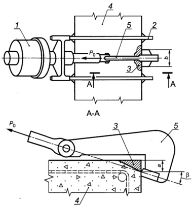
1 - device with a loading device and a force meter; 2 - support frame; 3 - chipped concrete; 4 - test structure. 5 - grip with bracket
"Figure B.1 - Scheme of the rib shearing test"
B.4 In case of local chipping of a rib, the following parameters must be ensured:
Chip depth a = (20±2) mm;
Chip width b = (30±0.5) mm;
The angle between the direction of the load and the normal to the loaded surface of the structure β = (18±1)°.
Calibration dependence for the peel-off method with a standard test scheme
When carrying out tests using the peel-off method according to the standard scheme in accordance with Appendix A, the cubic compressive strength of concrete R, MPa, can be calculated using the calibration dependence according to the formula
where m 1 is a coefficient taking into account maximum size coarse aggregate in the breakout zone and taken equal to 1 when the aggregate size is less than 50 mm;
m 2 - proportionality coefficient for the transition from pullout force in kilonewtons to concrete strength in megapascals;
P - pullout force of the anchor device, kN.
When testing heavy concrete with a strength of 5 MPa or more and light concrete with a strength from 5 to 40 MPa, the values of the proportionality coefficient m 2 are taken according to Table B.1.
Table B.1
|
Type of anchor device |
Range of measured compressive strength of concrete, MPa |
Diameter of anchor device d, mm |
Depth of embedding of anchor device, mm |
The value of the coefficient m 2 for concrete |
|
|
heavy | |||||
Coefficients m2 when testing heavy concrete with an average strength above 70 MPa should be taken according to GOST 31914.
Calibration dependence for the rib shearing method with a standard test scheme
When testing by the rib shearing method according to the standard scheme in accordance with Appendix B, the cubic compressive strength of concrete on granite and lime crushed stone R, MPa, can be calculated using the calibration dependence according to the formula
R=0.058m(30P+P 2),
where m is a coefficient that takes into account the maximum size of coarse aggregate and is taken equal to:
1, 0 - for aggregate size less than 20 mm;
1.05 - with aggregate size from 20 to 30 mm;
1, 1 - with aggregate size from 30 to 40 mm;
P - shearing force, kN.
Appendix D
(required)
Requirements for instruments for mechanical tests
Table E.1
|
Name of device characteristics |
Characteristics of instruments for the method |
|||||
|
elastic rebound |
shock pulse |
plastic deformation |
chipping ribs |
separation with chipping |
||
|
Hardness of the striker, striker or indenter HRCе, not less | ||||||
|
Roughness of the contact part of the striker or indenter, µm, no more | ||||||
|
Diameter of striker or indenter, mm, not less | ||||||
|
Thickness of disk indenter edges, mm, not less | ||||||
|
Conical indenter angle | ||||||
|
Indentation diameter, % of indenter diameter | ||||||
|
Perpendicularity tolerance when applying a load at a height of 100 mm, mm | ||||||
|
Impact energy, J, not less | ||||||
|
Rate of load increase, kN/s | ||||||
|
Load measurement error, %, no more | ||||||
|
* When pressing the indenter into the concrete surface. |
||||||
Methodology for establishing, adjusting and assessing the parameters of calibration dependencies
E.1 Calibration equation
The equation for the relationship “indirect characteristic - strength” is taken to be linear according to the formula
E.2 Rejection of test results
After constructing the calibration dependence according to formula (E.1), it is adjusted by rejecting individual test results that do not satisfy the condition:
where R i n is the strength of concrete in i-th section, determined from the calibration dependence under consideration;
S - residual standard deviation, calculated by the formula
 ,
,
here R i f, N - see the explanation to formula (E.3).
After rejection, the calibration dependence is established again using formulas (E.1) - (E.5) based on the remaining test results. Rejection of the remaining test results is repeated, considering the fulfillment of condition (E.6) when using a new (corrected) calibration dependence.
Partial concrete strength values must satisfy the requirements of 6.1.7.
E.3 Parameters of the calibration dependence
For the accepted calibration dependence, determine:
Minimum and maximum values of the indirect characteristic H min, H max;
Standard deviation S T . H. M of the constructed calibration dependence according to formula (E.7);
Correlation coefficient of the calibration dependence r according to the formula
 ,
,
where the average value of concrete strength according to the calibration dependence R̅ n is calculated using the formula
here the values of R i n, R i f, R̅ f, N - see explanations to formulas (E.3), (E.6).
E.4 Correction of the calibration dependence
Correction of the established calibration dependence, taking into account additionally obtained test results, must be carried out at least once a month.
When adjusting the calibration dependence to existing results tests add at least three new results obtained at the minimum, maximum and intermediate values of the indirect indicator.
As data is accumulated for constructing a calibration dependence, the results of previous tests, starting from the very first, are rejected so that the total number of results does not exceed 20. After adding new results and rejecting old ones, the minimum and maximum values of the indirect characteristic, the calibration dependence and its parameters are established again according to the formulas (E.1) - (E.9).
E.5 Conditions for using the calibration dependence
The use of a calibration relationship to determine the strength of concrete according to this standard is allowed only for values of the indirect characteristic falling in the range from H min to H max.
If the correlation coefficient r< 0, 7 или значение S T . H . M / R̅ ф >0.15, then monitoring and assessing the strength based on the obtained dependence are not allowed.
Appendix G
(required)
Technique for linking the calibration dependence
G.1 The value of concrete strength, determined using a calibration relationship established for concrete different from the one being tested, is multiplied by the coincidence coefficient K c. The Kc value is calculated using the formula
![]() ,
,
where R os i is the strength of concrete in the i-th section, determined by the tear-off method with chipping or core testing according to GOST 28570;
R conv i is the strength of concrete in the i-th section, determined by any indirect method using the calibration relationship used;
n is the number of test sections.
G.2 When calculating the coincidence coefficient, the following conditions must be met:
Number of test sites taken into account when calculating the coincidence coefficient, n ≥ 3;
Each partial value R os i /R os i must be no less than 0.7 and no more than 1.3:
![]() ;
;
Each particular value R os i /R os i should differ from the average value by no more than 15%:
![]() .
.
Values of R os i / R os i that do not satisfy conditions (G.2), (G.3) should not be taken into account when calculating the coincidence coefficient K c.
Designation of the number of test sites for prefabricated and monolithic structures
I.1 In accordance with GOST 18105, when monitoring the strength of concrete of prefabricated structures (tempering or transfer), the number of controlled structures of each type is taken to be at least 10% and at least 12 structures from the batch. If a batch consists of 12 structures or less, a complete inspection is carried out. In this case, the number of sections must be at least:
1 by 4 m length of linear structures;
1 by 4 m2 area flat designs.
I.2 In accordance with GOST 18105, when monitoring the strength of concrete of monolithic structures at an intermediate age, at least one structure of each type (column, wall, ceiling, crossbar, etc.) from the controlled batch is controlled using non-destructive methods.
I.3 In accordance with GOST 18105, when monitoring the strength of concrete of monolithic structures at design age, continuous non-destructive testing of the strength of concrete of all structures of the controlled batch is carried out. In this case, the number of test sites must be at least:
3 for each grip for flat structures (wall, ceiling, foundation slab);
1 per 4 m length (or 3 per grip) for each linear horizontal structure (beam, crossbars);
6 per structure - for linear vertical structures(column, pylon).
The total number of measurement sections for calculating the characteristics of the uniformity of concrete strength of a batch of structures must be at least 20.
I.4 The number of single measurements of concrete strength using mechanical non-destructive testing methods at each site (the number of measurements at a site) is taken according to Table 2.
Test results presentation table form
|
Name of structures (batch of structures), design concrete strength class, concreting date or age of concrete of tested structures |
Designation(1) |
N section according to the diagram or location in axes (2) |
Strength of concrete, MPa |
Concrete strength class(5) |
|
|
plot(3) |
medium(4) |
||||
|
(1) Brand, symbol and (or) the location of the structure in the axes, zones of the structure, or part of the monolithic and prefabricated monolithic structure(grips), for which the concrete strength class is determined. (2) The total number and location of sites in accordance with 7.1.1. (3) Strength of the site concrete in accordance with 7.1.5. (4) The average strength of concrete of a structure, a zone of a structure or part of a monolithic and precast monolithic structure for the number of areas that meet the requirements of 7.1.1. (5) The actual strength class of concrete of a structure or part of a monolithic and prefabricated monolithic structure in accordance with paragraphs 7.3 - 7.5 of GOST 18105, depending on the selected control scheme. Note - Presentation in the column "Concrete strength class" of estimated class values or values of the required concrete strength for each section separately (assessment of the strength class for one section) is not acceptable. |
|||||
The strength of load-bearing and enclosing structures largely depends on the characteristics of the building materials used. Complex testing of concrete for tearing with spalling is classified as non-destructive and allows you to determine with high accuracy the parameters and quality of the mixtures used. Research is carried out in accordance with the requirements of GOST 22690-2015 using special instruments.
In our country this technique concrete testing has become widespread due to its versatility and convenience. The strength characteristics of the material are checked by directly impacting the concrete of the structure and causing partial chipping. During the research, the force is determined that makes it possible to tear off a fragment of a building structure using a leaf anchor embedded in a hole.
The procedure for testing concrete structures for tearing with spalling
The described control technique makes it possible to establish the strength indicators of the material in the measurement range from 5 to 100 MPa. This test method is applicable for four types of concrete:
- lungs;
- heavy;
- fine-grained;
- tension in monolithic and prefabricated reinforced concrete products.
Study of this building material by tearing off the anchor with chipping is carried out in the manner prescribed by the current GOST:
- Preparation of equipment and facility.
- Conducting research and recording the results obtained.
- Data processing using standard techniques.
- Creation of a calibration dependence.
To carry out the program, two types of samples are made, control and basic, from materials of the type being studied. They must be cured under the same conditions as the tested products. In this case, basic samples are necessary to determine the indirect characteristics of concrete mixtures.
Preparatory work
Trial building structures and concrete products using this technique will require significant time. Before conducting concrete research by tearing with chipping, a number of preparatory measures are carried out:
- The device and anchor device are inspected and their technical condition is checked.
- The chosen location for installing the device is not necessarily flat; the curvature of the surface should not interfere with its use.
- A hole is drilled into the structure under study, from which dust and debris are removed. At a temperature environment Below -10 °C, the hole and the adjacent mass along its entire length are heated.
The area under study, where it is planned to tear off the concrete with spalling, must be located at a sufficient distance from the prestressed reinforcement. In addition, the area under study should not experience heavy operational loads.
Procedure for conducting concrete strength studies
Testing of concrete by the pull-out method can be carried out, including using anchors laid before the construction of cement-sand mixtures is poured.  The described method for testing the strength characteristics of concrete, which involves tearing and spalling, involves performing a number of operations:
- A petal anchor is inserted into the pre-drilled hole to its full depth and fixed in it.
- The device is installed and the embedded device is connected to it.
- Gradually increase the load (increase rate –1.5 -3 kN/s).
- Recording of readings: forces and values of anchor slippage (the difference between the depth of the hole and the hole at which a fragment of material is torn off from the massif).
The result obtained - the pullout force - is entered into the test report and is used to construct a calibration dependence. In this case, the accuracy of measuring the slip rate of the embedded anchor must be at least 0.1 mm.
Processing the results
The data recorded during the research makes it possible to evaluate the strength of the mentioned material by the magnitude of the applied load at which chipping occurs. The value of the force at which a fragment of concrete comes off as a result of chipping is multiplied by a correction factor. The latter is calculated using the following formula:
γ=h 2 /(h- Δh) 2,
where h is the depth of the anchor,
and Δh is the slip value.
If maximum length of the material that was torn off during the test is more than twice the minimum, the result is considered to be indicative. Do the same if the hole depth exceeds the amount of anchor slip by 5% or more. The use of indicative values to determine the strength class of a material is unacceptable.
The tests are invalid if the depth of the hole differs from the length of the anchor by 10% or if reinforcement is found at a distance not exceeding the depth of the hole.
Advantages and features of the research method
One of the main advantages of the described method is high accuracy over a wide measurement range. Moscow is the leader in the number of facilities being built, and such tests of concrete for tearing off followed by chipping are in demand. This method of assessing the strength of a material is the only method that allows constructing a calibration relationship without destroying the structure.
When monitoring characteristics using this method, it is necessary to take into account climatic conditions, as well as a number of other factors. In particular, the thickness of the product should be twice the depth of the anchor, and the distance between the measurement points should exceed given value five times. Order testing of concrete by tearing off with chipping in Moscow by affordable price You can directly on our website or by calling our contact number.