A garage press is a machine that is designed for straightening, compression, bending sheet materials, pressing or pressing out bearings, as well as for other plumbing work.
Those devices that are designed to perform the specified plumbing work have a very simple and compact design, which differs from high-power industrial hydraulic presses. The maximum value of force produced by such a press, depending on the specific model, can range from 5 to 100 tons.
For use in a garage, a force of 10-20 tons is sufficient. This allows you to perform traditional car repair work.
In addition to the force developed, the press also has such basic characteristics as the piston stroke, the working range of the frame, the presence of a pressure gauge, dimensions and weight.
A garage press typically uses a manual drive. In other words, the design of the press uses a manual or manual hydraulic pump, which is matched to the power cylinder according to the volume of oil.
A hydraulic press consists of two chambers with pistons connected to each other by an oil line. The operating principle of a hydraulic press is based on Pascal's law. That is, the pressure force on the workpiece is as many times greater than the force applied to the piston, how many times the area of the piston is greater than the area on which the press rod acts.
There are also pneumatic hydraulic presses that use a pneumatic piston. When compressed air is connected, it begins to pump oil into the cylinder. Some models of presses have a pneumatic pedal for ease of operation.
The disadvantage of pneumohydraulic presses is the need for compressed air.
Unit types
According to the method of execution, garage presses are of floor and tabletop types.
The advantages of a tabletop press are compactness and ease of use. A floor-mounted press has significantly larger dimensions, and therefore requires additional space in the garage.
Element design
To make the press frame, thick-sheet hardened steel is used. The structure is strengthened with powerful stiffening ribs.
The profiled base of a factory-made press usually has holes for fastening to the floor or table. The height of the desktop in serial models is usually easily adjustable.
For this purpose, the design of presses with high pressing force includes a mechanical lift with a rotating handle. A mechanical rod with a trapezoidal thread serves to transmit the pressing force and ensures the reliability of the design. Serial press models are usually equipped with an automatic rod return system and safety valve, protecting against emergency situations during overloads. The pressure gauge is installed in a location convenient for the operator and shows the current load force.
All elements hydraulic system built into the monoblock design of the press, protecting them from accidental damage. The garage press kit includes two combination V-plates.
Making a garage press yourself

Hydraulic press device
Experienced car enthusiasts often make a garage press with their own hands from available and inexpensive materials and components. This allows them to independently perform a whole series small repair work: pressing bearings, silent blocks, rubber bands jet thrust and so on.
Materials for production
To manufacture it on the construction market you need to purchase:
- Channel No. 8, 80 mm wide (it is advisable to immediately cut it on site to the required dimensions 6 * 500 mm);
- Rectangular pipe 40*60 mm, also cut to size 2*1000 mm+2*500 mm;
- Bolts M8*30 – 4 pcs., M10*80 – 4 pcs., M12*80 -10 pcs., M12*150 – 2 pcs. with nuts;
- Plate 250*250*8 mm;
- Strip 4*40*60 mm – 4 pcs.;
- Corner 50*50*300 mm – 2 pcs.;
- Corner 25*25*250 mm – 2 pcs.;
- 12 ton bottle jack;
- Bridge mushroom with shifted splines;
- 2 door springs 300mm each.
You can additionally install a bearing puller on the base of the press. For this you will need:
- Hairpin M16*1000 mm – 2 pcs.;
- Hairpin M8*1000 mm – 1 pc.;
- High nut M16 – 4 pcs.;
- Small two-legged puller.
In principle, the purchase of metal products can be made at a metal warehouse, selecting the required sizes from among the remains of illiquid assets. As a rule, such materials are much cheaper.
Holes are pre-drilled in the channels and corners. Then a homemade garage press is assembled from metal blanks using fasteners. The bottle jack plays the main role in the device - it generates pressing force.
To do this, it is placed on a movable desktop. The jack can be removed from the press at any time and used for its main purpose. The movable work table is supported by 2 suspended door springs. A bridge mushroom is attached to it from below with M8 bolts, which will serve as a rod. To make the upper part of the puller, two 40*4*60 mm strips are welded to a high nut under the stud. Two puller hooks are welded to two studs.
This design of a homemade garage press is as simple as possible and allows, if necessary, to disassemble it yourself and transport it to another place.
Do you need abs? No problem, you can do it yourself! I bring to your attention just such instructions. It will allow you to make an excellent electro-hydraulic press, and if you want, it can be simply hydraulic.
The device works on the basis, the device is driven by a small motor similar to the old one washing machine. All spare parts are inexpensive, and in the end we get a very cool and useful car!
Materials and tools used
List of materials:
- ;
- an old grinder (you need a gearbox from it);
- steel pipes (square);
- corner;
- channel;
- steel plates and other scrap metal;
- engine from washing machine(or similar);
- powerful spring;
- bolts with nuts;
- cable and switch (keyboard);
- dye.
List of tools:
- drilling machine and drill;
- grinder, preferably a band cutting machine;
- vice;
- hammers, pliers, wrenches, etc.;
- ;
- ruler;
- marker;
- clamps.
Press manufacturing process:
Step one. We make a frame
Conventionally, the entire assembly process can be divided into only two parts, this is the manufacture of the frame, as well as the installation of the jack and engine.
Let's start in order, how the frame is made.


The frame consists of two guides, square steel pipes are used as them. They need to be thoroughly cleaned of rust so that nothing gets stuck. The author drills rows of holes in the drains. Thanks to these holes, a thrust platform will be installed; it rests on bolts with a large cross-section. If desired, you can always raise or lower the platform.


Now we begin to manufacture the “square pipes” to which the “elevator”, that is, the pressure platform, is attached and on which it rides. To make these parts, we take cardboard and wrap it around the guides. Next, take a corner, cut off the necessary pieces and press them on top with clamps. We weld the resulting structure, then carefully knock it down. Thanks to the cardboard, we will get a gap between the stand and the pipe. Cut the manufactured part into two parts, thoroughly weld the seams and clean them with a grinder.


Racks can be installed! We use a corner or pipes as a base and weld a good stop so that the installation does not wobble. We also weld a piece of pipe on top, or better yet a channel, since high loads are formed here. The author also decided to plug the holes in the pipes; he cut out steel plates for this and welded them.
Step two. We attach the “elevator”
The author makes the “elevator,” that is, the pressing platform, from a massive channel. The material must be strong and withstand loads of several tons. We weld it well in the right places.


The thrust platform must also be very strong; the author makes it from two channels. We cut two pieces, and then drill holes in them and tighten them using threaded rods and nuts. Massive bolts and nuts are used as support for the platform.


Step three. Place for installing a jack
The jack is installed on the machine in the classic form, that is, “head up”. To prevent the stop from coming off, you will need a piece round pipe suitable diameter. We cut it, try it on, weld it to the upper support.
As for the base, here you can weld several steel plates as a stop so that the jack, God forbid, does not jump off under load.


Almost everything is ready, we already have a press, which is driven by human muscular power. As a working tool, the author welds a “finger” under the heads, now you can always install the desired attachment.


A powerful spring must be installed between the upper support and the “lift”; it allows you to return the machine to its original state after turning it off. I think you can guess how this is done. It is advisable to use two springs, one on each side.


Step four. Preparing the gearbox
As a gearbox, the author uses spare parts from old grinder. We disassemble the angle grinder and pull out the anchor. From the anchor you need to cut off the bow part, which is inserted into the gearbox. A nut is attached to this axle; the author puts it on an already manufactured press, having previously adjusted the thickness of the axle to drilling machine. To be sure, the nut can be secured to the axle by welding.


Step five. Engine Mounting Plate
The engine housing is usually made of aluminum, which is not very good, because nothing can be welded to it. We take a steel plate, drill holes, and attach it to the engine using bolts.


Step six. Installing the gearbox on the engine
Using steel plates, install the gearbox on the engine. Now, after switching on, the torque from the motor shaft will go to the gearbox!


You need to install a crank on the gearbox axis; it is done very simply. You will need a strong steel plate as well as a nut. We weld one to the other and install it on the axle. To transmit movement, you will also need a bolt with a nut and two bearings.


Step seven. Working pedal
You need to install a pedal on the jack that will receive movement from the crank. Here you will need a square pipe. Cut out a “window” inside it; two bearings will be installed here. We secure the pedal with a bolt and nut and do not forget about the washers.
Now you can connect the gear crank to the pedal!


Step eight. Connecting the engine to the jack
The engine needs to be secured to a jack; to do this, we make a special bracket from the corners, which clamps the jack when tightening the nuts. Weld the engine with the gearbox to this bracket using square pipes and connect the transmission unit (crank). Order! Apply power and see how the electrical works hydraulic jack!
For some operations home handyman a press with significant compression force may be required, but the purchase of equipment of this class will be completely unjustified. Today we will tell you how to assemble a reliable press based on a hydraulic car jack in a few hours.
What and how to assemble a frame for the press?
The material for the frame, its structural strength and the method of assembly should be determined by the pressure that the jack is capable of delivering. For accurate calculations, it is important to understand in which direction the loads act during operation.
The base of the press is a rectangular U-shaped frame made of a channel or a paired steel angle. The main acting force is the resistance to compression, expressed in concentrated load. The main force is concentrated in the centers of the horizontal crossbars. The forces that stretch the vertical racks of the press and the phenomena of deformation in compressed parts can be completely neglected.
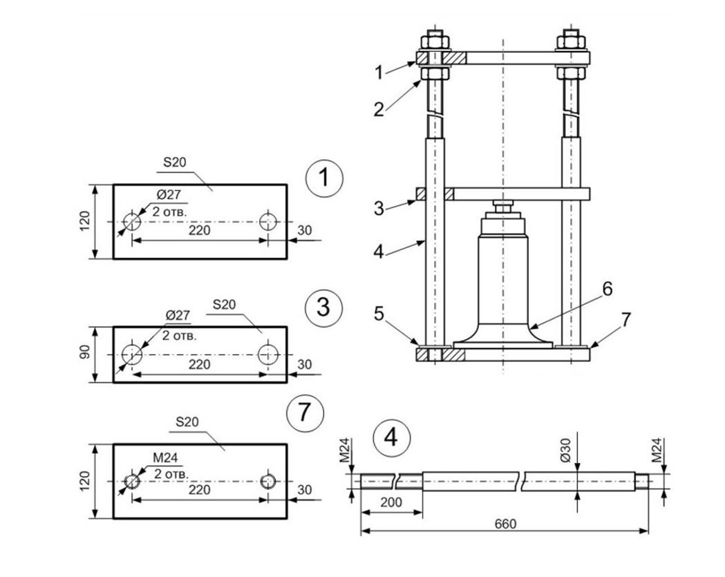
 1 - upper thrust beam; 2 - bolts; 3 - jack 20 t; 4 — return springs; 5 - movable beam; 6 — locking pin; 7 - adjustable support beam; 8 - transverse beam; 9 - legs from corners
For installation with a compressive force of up to 5 tons, you can safely use the following to make a frame:
- Channel according to GOST 8240-89, standard size 8P.
- A pair of hot-rolled angles according to GOST 8509-93, size 50x5 mm, connected with 10 mm rods every 20-25 cm, or with a solid weld.

Let us immediately make a reservation that we provide approximate data on rolled metal for a frame with an internal window no wider than 100 cm. By analogy, when using a jack with a force of up to 10 tons, the frame should be made from:
- Channel size 10P.
- Twin angle steel 63x7 mm, solid seam connection with internal inserts of nominal cross-section.

If the required compression force reaches 15 tons or higher, then the frame should be made of:
- Channel size 14P.
- Twin angle 75x8 mm, connection similar to the previous one.

The above proposal for rolled metal products implies a tenfold safety margin, which completely eliminates exceeding the limit of elastic deformation and is normal for installations of this kind. All frame joints must be welded with solid double-sided seams and butt cut. If the connection is not made by welding, assembly with bolts or cotter pins is allowed. In this case, it is necessary to take into account the maximum permissible load for cutting

At bolted connection the main load becomes dispersed and the compression force of the press must be divided by the number of bolts or fingers. The destructive shear force of bolts made of the most common steel ST-3 is:
- M10 - about 2500-3000 kg.
- M12 - 4000-4500 kg.
- M14 - 5500-6000 kg.

To ensure the required safety margin, each fastening element must experience a load five times less than the destructive load. For steel fingers, the force can be taken 10-15% higher than the specified values. If required quantity If fasteners cannot be placed in a corner joint, the strength should be increased with gussets, for which it is preferable to use corner steel instead of sheet steel. The same applies to the welded frame structure, which also helps to avoid the use of excessively massive rolled steel.

In addition to the loaded upper part, the frame includes two racks with legs that provide the press with sufficient stability, and a cross beam that can be adjusted when processing parts different sizes. The cross-section of the upper and lower beams must be equivalent, as well as the cross-section of their fastening elements. Everyone is free to implement the legs and support according to their own considerations; they do not experience work loads in addition to the own weight of the press. The only requirement is the presence of a bottom crossbar, which gives the structure additional rigidity.
Which jack to use and how to modify it
The most affordable and suitable for making a home press would be a glass-type hydraulic car jack. As mentioned above, you have the right to choose the working force to suit your tasks; there are relatively inexpensive devices on sale that can squeeze up to 20 tons or even more.

The main problem with using these jacks is their inability to work in an upside-down position. It seems most logical to mount the jack permanently on the upper beam and use the lower one as a support for the part. However, this will require modification of the hydraulic mechanism.
The first option for modifying the jack is to install an additional expansion tank with a capacity of about 300 ml. The tank is connected to the filler hole of the jack with a regular silicone tube. To ensure a tight fit, you can use threaded fittings for the oxygen hose, which are available in any auto parts store.

Another modification option will require disassembling the jack. It is necessary to completely drain the oil and pump the plunger, then tighten the upper clamping nut, holding it in a vice. After this, the outer glass is loosened with a rubber mallet; it should come out of the seat ring at the base of the jack. Immediately next to the plunger lever there is a hole for collecting the working fluid. The whole problem lies here: the glass is not completely filled and therefore, when upside down, the hole does not come into contact with the oil. To eliminate this, you need to tightly press a tube into it, almost the entire height of the glass.

If you do not redo the jack, you will have to implement a more complex mechanism with an additional third beam. It should slide along the side guide posts and have a tight enough fit so that the jack does not move when pressure is pumped up. In our case, the jack is simply attached in an inverted position to the center of the upper beam. There is no need for massive bolts here; it is enough to make a couple of holes in the jack’s support plate and ensure fixation with M10 or M8 bolts that can withstand the weight of the jack itself and a slight shear force on initial stage compression.

Manufacturing of clamping pads
The jack rod is not very convenient to use; it usually requires an increased area of compressing headstocks to use a wide range of molds and work with large parts. In this case, the force must be distributed evenly over the entire area of the compressed surfaces, without causing deformation.
In the simplest case, short, solid ingots can act as clamping blocks. It is enough to simply make blind holes with threads for fixing them to the main structure of the press. But this kind of detail is not always available to the average person, so we offer an option self-made headstocks that can withstand significant compression forces without harm.
The top headstock must have the ability to be integrally fastened with the jack rod, preventing shifting during operation. Simply put, a blind hole should be made in the headstock into which the heel of the jack will fit with minimal clearance. You will also need a couple of holes for attaching the return mechanism springs.

Both headstocks can be made from two sections of channel or four pieces of angle, forming a parallelepiped with open side edges. Seams on the planes through which the axis of the main working force passes should be welded with a continuous seam from the inside, the rest - from the outside. One of the faces is blanked with a square insert, after which the internal cavity is filled with sand concrete grade 500. After hardening, the headstock is welded on the other side, so two incompressible blocks are obtained.
To fit it on the jack, it is enough to weld a piece of pipe of the appropriate diameter in the upper part of the headstock, which will act as a casing for the glass. For even greater reliability, a washer with a hole for the heel of the rod is attached to the bottom of the sleeve. The lower headstock can simply be placed on an adjustable beam, but it is better to weld a couple of corners or steel rods that limit the shift.
Adjustable support beam
As you already know, the lower beam must have a cross-section no smaller than that of the upper one, but it differs in design. Support table It is made of two channels, with the ribs facing outward, which are placed on opposite sides of the racks and welded in the central part with inserts from angle or thick reinforcement. There is free space along the center of the beam, which explains the need to make a lower support block. The latter should rest on at least half the width of each shelf; the shear stops are welded in the center of the lower part.

The best option for fixing the beam to the racks is with the help of massive steel pins. To do this, a series of round notches at different heights with a parallel arrangement should be made in the vertical channels of the frame. As you understand, the diameter of the pins cannot be less than the total cross-section of all the bolts used to fasten the upper part of the frame.

Return mechanism
The last part of the structure homemade press- a spring mechanism that will fold the jack when the bypass valve is open. For this purpose, ordinary springs for finishing doors are suitable, which can be purchased in unlimited quantities at any hardware store.

The task is complicated when using an upper headstock, the significant dead weight of which will not allow the springs to compress. Alternatively, you can increase the number of springs to four or six, or use more powerful extension springs for the gate.

If there is no upper block, it is necessary to secure the springs to the jack rod. To do this you will need a washer, internal hole which is larger than the rod adjusting screw, but smaller than the piston diameter. The spring is attached to it through two small holes along the edges and fixed to the top beam in the same way or on welded hooks. It is not necessary to position the spring strictly vertically; you can compensate for the excess length with an inclined position.

Often those who like to repair or tinker with something have a need to process parts and assemblies by pressure (pressing). A hydraulic press, designed by yourself, will be an indispensable aid in this.
1 Hydraulic press - briefly about the purpose and principle of operation
A hydraulic press is equipment designed for processing materials and various products by pressure. The device is driven by a liquid that is under high pressure. The operation of the press is based on Pascal's law.
The equipment consists of 2 chambers (cylinders). In the first, smaller one, the liquid is brought to a state of high pressure and fed through a pipeline or a special channel into a larger working cylinder, where the incoming liquid creates a force on the piston that is transmitted to the material being processed through an actuator. A necessary condition operation of the press is the presence of a stop that does not allow movement of the part or workpiece under the influence of the working piston . Special oils are used as liquids.

In modern industrial hydraulic presses, the location of the working cylinder is most often vertical and sometimes horizontal. Depending on its purpose and the type of materials processed, this equipment develops forces from several tens to several thousand tons. The press is widely used in metalworking for stamping, forging, straightening and bending, extruding profiles and pipes, as well as for briquetting, packaging, pressing various materials, production of rubber, plastic, wood chip products and in many other areas.
2 Why do you need a press at home - some applications
In a home workshop, a small power press can become a valuable assistant in car repairs and other work. In order to press out a bearing or silent block and press a new one in its place, you do not need to contact a car service center and pay a lot of money. Using a press, you can bend a metal workpiece, straighten it, securely glue two parts together under pressure, press plastic bottles, tin cans, paper or cardboard, squeeze out the oil or moisture.

Buying a factory-made press will cost a pretty penny. But this equipment can be made independently, spending only on necessary materials. In this case, it will be possible to create a device tailored and adapted to specific needs, taking into account the tasks being solved. Since a homemade hydraulic press will in any case require some space, if there is no room for a workshop, it can be placed in the garage.
3 DIY hydraulic press - designs and drawings
For a home workshop, a press that develops forces of 10–20 tons or even less is quite enough - it all depends on the range of tasks. In addition to effort, this equipment has the following main characteristics:
- dimensions;
- piston stroke;
- presence of a pressure gauge;
- operating parameters of the bed.
To create pressure in the working cylinder, a manual built-in or separate hydraulic pump is usually used. It all depends on the choice of equipment for making the press. The simplest, most easily implemented version of a homemade press is a design based on a bottle-type hydraulic jack, which has a manual built-in pump.

Before you start manufacturing a press, you need to decide what kind of work it will be designed for, and, accordingly, what force it should develop. After this, you need to select and purchase a suitable jack (if it will be used when assembling the press).
Next, most important stage– creating a drawing of the future press. Any offered on the Internet for self-assembly The hydraulic press, the drawings to which are attached, was designed and made on the basis of existing metal materials And hydraulic equipment. Therefore, if you strictly follow other people’s developments, then assembling the press can stretch to infinity and will consist of reworking and adjusting the design taken as a basis to the purchased hydraulic jack.

When creating a drawing, you first need to select the operation scheme of the pressing equipment:
- The jack is installed on the base of the bed and presses upward.
- The jack is fixed at the top of the bed and presses down.
At the same time, we must not forget that for manufactured jacks, the correct working position, provided by the manufacturer, is vertical, with the retractable rod up - it cannot be turned over.
As a rule, the first option is used. The second is more convenient for certain types of metalworking work (in particular, for pressing out bushings and bearings from any parts).
4 Development of a drawing of a press with a hydraulic jack
Next, they develop a bed - a frame inside which the jack will put pressure on the parts. It must be strong and designed to withstand the force developed by the jack with a reserve, since the driven press will simultaneously press up and down, trying to tear the frame. The base of the bed must provide sufficient stability for the press and, preferably, be shaped like a platform. The width of the frame opening depends on the dimensions of the materials intended for processing, but it must be no less than the sum of the dimensions of the installed elements of the pressing equipment.
Height - consists of the size of the jack, the desired free play of its rod, the thickness of the movable work table and the height of the objects intended for processing. In operation scheme 1, the jack is installed on the base, and the top of the frame will serve as a stop for the parts. The force from the rod will be transmitted to the object through the movable work table. It is mounted on top of the jack on a frame along which it should move freely up and down, held by side guides.

Tension springs are attached to both sides of the jack - one eye to the base of the frame, and the other to the movable table. Their purpose is to compress the jack to its original state when the rod is not extended (the stiffness and size of the springs must be appropriate). An option is possible when the rod is fitted with a device in the form of a mandrel, to which one of the spring lugs is attached - the second is fixed to the base.
The second scheme of the press operation assumes that the support for the parts will be the base of the frame, and the jack is installed on a movable table, which is suspended from the top of the frame on tension springs. In both working schemes, a socket is provided under the head of the jack rod on the interface unit (from the bottom of the moving table (option 1) or the top of the frame (option 2). This can be a small piece of pipe of a suitable diameter.

To adjust the free play of the jack rod and, accordingly, the height of the objects being processed, the following solutions are possible:
- in the upper part of the frame a screw drive with a steering wheel is made. By screwing in a screw with a plate at the end, it will be possible to reduce the clearance for parts inside the frame;
- provide a removable stop in the form of a moving work table, which can be fixed to the frame with bolts and nuts or rods. To do this, holes are drilled in the frame with a height increment less than the stroke of the jack rod;
- provide for the use of replaceable inserts-linings made of solid or hollow steel profile;
- combined use of the above methods.
All dimensions in the drawing must be indicated taking into account not only the dimensions of the jack, the processing objects, but also the dimensions of the rolled metal intended for use in assembling the press.
5 What materials and tools are needed to make a press?
You will need the following tools:
- welding machine;
- electrodes;
- hacksaw or angle grinder with cutting disc for metal.
As power unit– selected hydraulic jack. Tension springs – door springs, from front car seats or others. When the jack is positioned at the bottom, a bridge fungus with shifted splines can be used as a part of the pulling device - it is put on the rod, springs are attached to it and the base of the frame.

Rolled metal that can be used (volume and dimensions according to the developed drawing):
- channel from No. 8 and above, rectangular or square pipe from 40x40 mm, corner from 50x50 mm - for the frame, its base, removable stop, movable work table;
- a piece of steel sheet from 8 mm - if necessary, laying it on the base or other structural elements in order to level the surface;
- steel strip 10 mm - for guides, frame stiffeners (if necessary);
- a piece of pipe for the head of the jack rod (of suitable diameter, approximately 1 cm long).
6 How to make a hydraulic press yourself?
After creating the drawing and preparing necessary tools, materials, components it will be clear how to make a hydraulic press. First, all the metal is cut to the dimensions indicated on the drawing. , if they are provided for by the design, on the parts designated for this purpose.
Then the base and seams at the joints are welded from the sections at the top and bottom. A steel plate of appropriate size is attached on top by welding. By using welding machine They make a U-shaped structure with strictly right angles, which is securely welded to the base - the frame is ready.

A movable work table is made. To do this, you can use a channel or pipe cut to a length less than the intermediate distance between the frame posts. A piece of pipe is welded to the pipe under the jack rod. As table guides, strip pieces with a length equal to the width of the bed are used. Having inserted the pipe between the frame posts, place strips on the sides and tighten the entire structure with bolts and nuts. The removable adjusting stop is made in the same way, but holes are drilled in the strips opposite the racks to fix them at the desired height.

Then in the designated places in an accessible way secure the tension springs. Having pulled out the moving work table, install a jack - a hydraulic press, made with your own hands, ready. When it is not needed, the jack can be easily removed and used for its intended purpose.
You can construct a hydraulic press in a home workshop using available rolled metal. The main working element of any hydraulic press is a car hydraulic jack. Most often, the press uses a common design for a car jack - a bottle jack. Jacks of this type, depending on the design features, can lift from 2 to 100 tons. A huge advantage of a car hydraulic jack is the simplicity of its design and ease of use.
Manufacturing of the structure base, racks and stops
The base for the device can be made from any available material. The main requirement for this structural unit of the device is to ensure reliable stability of the entire installation during operation. In order to ensure maximum structural stability, the hydraulic press must be designed in such a way that the center of gravity of the device is located as low as possible.

For floor type structures, the base can be assembled from channels or thick-walled corners. When making a tabletop hydraulic press, you can use thick-walled pipe, having a square cross-section. When using the base as a press platform, a thick-walled sheet of metal will need to be welded on top of the base. Iron can be used for construction only if the metal thickness is 10 mm or more.
After making the base, you can begin manufacturing the following structural elements of the device - racks and stops. These elements can also be made from scrap materials. When determining the dimensions of these elements, it is necessary to take into account some features of the intended operation of the device.
First of all, you need to find out the amount of extension of the rod used in the jack device. To this parameter you need to add the height of the hydraulic jack body and the thickness of the metal of the platform serving as a support.
The device stop is made of a material similar to that from which the device stands are made. The size of the stop must be equal to the width of the device platform.
The fixed thrust element and the racks connected together geometrically represent a U-shaped structural element. All structural elements are connected into a single structure using a welding unit. After connecting the racks and the fixed thrust element of the device by welding, the entire structure is attached to the previously manufactured base.