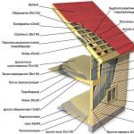
Types of overhead line supports
In the production of metal structures for power lines The following types of overhead line supports are distinguished:
intermediate power line supports,
power line anchor supports ,
power line corner supports and special metal products for power lines. Varieties of construction types air lines power transmission lines, which are the most numerous on all power lines, are intermediate supports that are designed to support wires on straight sections of the route. All high-voltage wires are attached to power line cross-arms through supporting garlands of insulators and other structural elements of overhead power lines. In normal mode, overhead line supports of this type take loads from the weight of adjacent half-spans of wires and cables, the weight of insulators, linear reinforcement and individual elements of the supports, as well as wind loads caused by wind pressure on the wires, cables and the metal structure of the power line itself. In emergency mode, the structures of intermediate power transmission line supports must withstand the stresses that arise when one wire or cable breaks.
Distance between two adjacent intermediate supports of overhead lines called the intermediate span. Overhead line corner supports can be intermediate or anchor. Intermediate corner elements of power transmission lines are usually used at small angles of rotation of the route (up to 20°). Anchor or intermediate corner elements of power transmission lines are installed in sections of the line route where its direction changes. Intermediate corner supports of overhead lines in normal mode, in addition to the loads acting on the usual intermediate elements of power lines, perceive the total forces from the tension of wires and cables in adjacent spans, applied at the points of their suspension along the bisector of the angle of rotation of the power line. The number of anchor corner supports of overhead lines is usually a small percentage of the total number on the line (10... 15%). Their use is determined by the installation conditions of the lines, the requirements for the intersections of lines with various objects, natural obstacles, i.e. they are used, for example, in mountainous areas, and also when intermediate corner elements do not provide the required reliability.
Are used anchor corner supports and as terminal wires from which the line wires go to the switchgear of a substation or station. On lines running in populated areas, the number of power line anchor corner elements also increases. The overhead line wires are secured through tension garlands of insulators. In normal mode for these power line supports , in addition to the loads indicated for the intermediate elements of the molding, the difference in tension along the wires and cables in adjacent spans and the resultant of the tension forces along the wires and cables act. Typically, all anchor-type supports are installed so that the resultant of the gravitational forces is directed along the axis of the support traverse. In emergency mode, power line anchor posts must withstand the break of two wires or cables. Distance between two adjacent power line anchor supports called an anchor span. Branch elements of power transmission lines are designed to make branches from main overhead lines when it is necessary to supply power to consumers located at some distance from the route. Cross elements are used to cross overhead line wires in two directions. Overhead line end posts are installed at the beginning and end of the overhead line. They perceive forces directed along the line created by the normal one-way tension of the wires. For overhead lines, power line anchor supports are also used, which have increased strength and a more complex design compared to the types of stands listed above. For overhead lines with voltage up to 1 kV, reinforced concrete racks are mainly used.
What types of power line supports are there? Classification of varieties
They are classified according to the method of fixation in the ground:
Overhead line supports installed directly into the ground - Power line supports installed on foundations Types of power line supports by design:
Free-standing power transmission towers - Posts with guys
Power line supports are classified according to the number of circuits:
Single-chain - Double-chain - Multi-chain
Unified power line supports
Based on many years of practice in the construction, design and operation of overhead lines, the most appropriate and economical types and designs of supports for the corresponding climatic and geographical regions are determined and their unification is carried out.
Designation of power line supports
For metal and reinforced concrete supports of 10 - 330 kV overhead lines, the following designation system has been adopted.
P, PS - intermediate supports
PVS - intermediate supports with internal connections
PU, PUS - intermediate corner
PP - intermediate transition
U, US - anchor-angular
K, KS - end
B - reinforced concrete
M - Polyhedral
How are overhead line supports marked?
The numbers after the letters in the marking indicate the voltage class. The presence of the letter “t” indicates a cable stand with two cables. The number separated by a hyphen in the marking of overhead line supports indicates the number of circuits: odd, for example, one in the numbering of a power line support is a single-circuit line, even number in numbering - two and multi-chain. The number separated by “+” in the numbering means the height of the attachment to the base support (applicable to metal ones).
For example, symbols of overhead line supports: U110-2+14 - Metal anchor-corner double-chain support with a stand of 14 meters PM220-1 - Intermediate metal multifaceted single-chain support U220-2t - Metal anchor-corner double-chain support with two cables PB110-4 - Intermediate reinforced concrete double-chain support
Overhead power lines. Support structures.
Supports and foundations for overhead power lines with voltage 35-110 kV have significant specific gravity both in terms of material consumption and in cost terms. Suffice it to say that the cost of installed support structures on these overhead lines is, as a rule, 60-70% of the total cost of constructing overhead power lines. For lines located on industrial enterprises and immediately adjacent territories, this percentage may be even higher.
Overhead line supports are designed to support line wires at a certain distance from the ground, ensuring the safety of people and reliable operation of the line.
Overhead power line supports are divided into anchor and intermediate. The supports of these two groups differ in the way the wires are suspended.
Anchor supports completely absorb the tension of wires and cables in spans adjacent to the support, i.e. used for tensioning wires. The wires are suspended from these supports using hanging garlands. Anchor-type supports can be of normal or lightweight design. Anchor supports are much more complex and more expensive than intermediate ones and therefore their number on each line should be minimal.
Intermediate supports do not perceive the tension of the wires or perceive it partially. The wires are suspended on intermediate supports using supporting garlands of insulators, Fig. 1.
Rice. 1. Scheme of the anchor span of the overhead line and the span of the intersection with the railway
On the basis of anchor supports can be carried out terminal and transposition supports. Intermediate and anchor supports can be straight and angular.
End anchor supports installed at the line exiting the power plant or at the approaches to the substation are in the worst conditions. These supports experience one-sided pull of all wires from the line side, since the pull from the substation portal is insignificant.
Intermediate lines poles are installed on straight sections of overhead power lines to support the wires. An intermediate support is cheaper and easier to manufacture than an anchor support, since under normal conditions it does not experience forces along the line. Intermediate supports make up at least 80-90% total number overhead line supports.
Corner supports are installed at the turning points of the line. At line rotation angles of up to 20°, anchor-type corner supports are used. When the angle of rotation of the power line is more than 20 o - intermediate corner supports.
Used on overhead power lines special supports following types: transpositional– to change the order of wires on supports; branch– to make branches from the main line; transitional– for crossing rivers, gorges, etc.
Transposition is used on lines with a voltage of 110 kV and above with a length of more than 100 km in order to make the capacitance and inductance of all three phases overhead power line circuits are the same. At the same time, the relative position of the wires in relation to each other on the supports is successively changed. However, this triple movement of wires is called a transposition cycle. The line is divided into three sections (steps), in which each of the three wires occupies all three possible positions, Fig. 2.

Rice. 2. Transposition cycle of single-circuit line wires
Depending on the number of chains suspended from the supports, the supports may be single-chain and double-chain. The wires are located on single-circuit lines horizontally or in a triangle, on double-circuit supports - reverse tree or hexagon. The most common locations of wires on supports are shown schematically in Fig. 3.

Rice. 3. The most common locations of wires and cables on supports:
a – location along the vertices of the triangle; b - horizontal arrangement; c – reverse tree arrangement
The possible location of lightning protection cables is also indicated there. The arrangement of wires along the vertices of the triangle (Fig. 3, a) is widespread on lines up to 20-35 kV and on lines with metal and reinforced concrete supports with a voltage of 35-330 kV.
The horizontal arrangement of wires is used on 35 kV and 110 kV lines on wooden supports and on lines over high voltage on other supports. For double-chain supports, it is more convenient from an installation point of view to arrange the wires in a “reverse tree” type, but it increases the weight of the supports and requires the suspension of two protective cables.
Wooden supports were widely used on overhead power lines up to 110 kV inclusive. The most common are pine supports and somewhat less common are larch supports. The advantages of these supports are their low cost (if local wood is available) and ease of manufacture. The main disadvantage is wood rotting, especially intense at the point of contact of the support with the soil.
Metal supports made of special grades of steel for lines of 35 kV and above, they require a large amount of metal. Individual elements are connected by welding or bolts. To prevent oxidation and corrosion, the surface of metal supports is galvanized or periodically painted with special paints. However, they have high mechanical strength and a long service life. Install metal supports on reinforced concrete foundations. These supports, according to the design of the support body, can be classified into two main schemes - tower or single-post, rice. 4, and portal, rice. 5.a, according to the method of fastening to the foundations - k free-standing supports, fig. 4 and 6, and guyed supports, rice. 5.a, b, c.
On metal supports with a height of 50 m or more, stairs with guardrails reaching the top of the support must be installed. In this case, each section of supports must have platforms with fences.

Rice. 4. Intermediate metal support for single circuit line:
1 – wires; 2 – insulators; 3 – lightning protection cable; 4 – cable support; 5 – support traverses; 6 – support stand; 7 – support foundation

Rice. 5. Metal supports:
a) – intermediate single-circuit on guy wires 500 kV; b) – intermediate V-shaped 1150 kV; c) – intermediate support of 1500 kV DC overhead line; d) – elements of spatial lattice structures

Rice. 6. Metal free-standing double chain supports:
a) – intermediate 220 kV; b) – anchor corner 110 kV
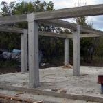
Reinforced concrete supports are carried out for lines of all voltages up to 500 kV. To ensure the required density of concrete, vibration compaction and centrifugation are used. Vibration compaction is carried out using various vibrators. Centrifugation provides very good compaction of concrete and requires special machines - centrifuges. On overhead power lines of 110 kV and above, the support posts and traverses of the portal supports are centrifuged pipes, conical or cylindrical. Reinforced concrete supports are more durable than wooden ones, there is no corrosion of parts, they are easy to operate and therefore are widely used. They have a lower cost, but have greater mass and relative fragility of the concrete surface, Fig. 7.

Rice. 7. Intermediate reinforced concrete free-standing single-circuit
supports: a) – with pin insulators 6-10 kV; b) – 35 kV;
c) – 110 kV; d) – 220 kV
Crossbeams of single-column reinforced concrete supports are galvanized metal.
The service life of reinforced concrete and metal galvanized or periodically painted supports is long and reaches 50 years or more.
MINISTRY OF EDUCATION AND SCIENCE OF THE RF
Federal State Budgetary Educational Institution of Higher Professional Education
Kazan State University of Architecture and Civil Engineering
Department of Geodesy
SELECTED CONVENTIONAL SIGNS
Guidelines
To perform calculation and graphic work by students studying in the field of “Construction”.
Kazan-2012
Compiled by: V.S. Borovskikh, M.G. Ishmukhametova
Selected symbols. Methodological instructions for performing calculation and graphic work by 1st year students of full-time study in the direction of “Construction”. The guidelines comply with the State General Education Standard.
Kazan State University of Architecture and Civil Engineering.
Compiled by: V.S. Borovskikh, M.G. Ishmukhametova
Kazan, 2012 – 17 p.
Ill. 90, table 1
Reviewer: SNS, Associate Professor, PhD, Department of Astronomy, Kazan State University M.I. Shpekin
Kazan State University of Architecture and Civil Engineering
The “Selected Conventional Signs for Topographic Plans at Scales 1:500 and 1:1000" contains the symbols of the most frequently encountered contours and terrain features. They must be learned and known by students studying at the university. “Selected Conventional Signs” are used when performing calculations graphic work and during summer geodetic practice for drawing plans for theodolite, tacheometric surveys, leveling by squares.
To draw topographic plans and maps of smaller scales, symbols are used, usually similar in appearance to symbols for scales 1:500 - 1:1000.
In “Selected Conventional Signs” the first column shows serial numbers. Conventional signs were selected from the official publication “Conventional signs for topographic plans at scales 1:5000, 1:2000, 1:1000, 1:500” - M.: Nedra, 2002, approved by the State Administration for Civil Engineering of Russia. The second column contains the names of conventional signs and explanations for them, and the third column contains images of various signs and their sizes. When drawing plans, the dimensions of the symbols must be observed, but not shown.
When drawing off-scale symbols, images of objects should be placed perpendicular to the southern frame of the plan.
The position of the object on the ground must correspond to the following points of the off-scale sign on the plan:
a) for signs of regular shape (circle, square, etc.) – the center of the sign;
b) for signs with a right angle at the base – the apex of the angle;
c) for signs in the form of a perspective image of an object - the middle of the base of the sign.
To draw symbols on plans and maps, ink and watercolors of different colors are used. The colors are shown in the legend to the symbols. If there are no such explanations, the symbols are depicted in black ink.
SELECTED CONVENTIONAL SIGNS
for topographic plans
scales 1: 1000, 1: 500
|
Name and characteristics of the topographic object |
Conventional sign of a topographical object |
|
|
Points of the state geodetic network |
||
|
Points of the state geodetic network on the mounds |
|
|
|
Points of the state geodetic network on buildings |
|
|
|
Points of geodetic condensation networks and their numbers |
||
|
Leveling benchmarks and their numbers |
|
|
|
Leveling benchmarks and wall marks |
|
|
|
Leveling benchmarks for soil construction, long-term |
|
|
|
Temporary leveling benchmarks |
|
|
|
Intersections of coordinate lines ( green) |
||
|
buildings: Residential fire-resistant: (brick, stone, concrete) 1) single-story; 2) above one floor |
||
|
Non-residential fire-resistant buildings: (brick, stone, concrete) 1) single-story; 2) above one floor |
||
|
Non-fire-resistant residential buildings: (wooden, adobe, etc.) 1) single-story; 2) above one floor |
||
|
Non-residential non-fire-resistant buildings (wooden, adobe, etc.) 1) single-story; 2) above one floor |
||
|
Buildings under construction |
||
|
Destroyed and dilapidated buildings |
||
|
Floor height mark for the first floor (inside the contour); Ground mark on the corner of the house |
||
|
1) stone with domes of different heights; 2) wooden with one dome |
||
|
1) stone; 2) wooden |
1)2) |
|
|
Small buildings: 1) individual garages; 2) toilets |
||
|
Slopes: Unfortified (figure 2,5 – slope height in meters) |
||
|
Unreinforced slopes (figure 102,5 – slope height in meters) |
||
|
Reinforced slopes (number 102,5 – slope height in meters; inscription - a method of strengthening) |
|
|
|
Open-pit mining of solid minerals (quarries, etc. (figure – depth in meters) |
|
|
|
Gas stations |
||
|
Electrical substations, transformer booths, and their numbers |
|
|
|
Wells and wells combined with water towers |
||
|
Electric lamps on poles |
|
|
|
Inspection wells (hatches) of underground communications: 1) without appointment; 2) on water supply networks; 3) on sewer networks; 4) on heating networks; 5) on gas pipelines |
||
|
Power transmission lines (PTL) in an undeveloped area (numbers – truss heights in meters, voltage in kV, number of wires or cables): 1) high voltage power lines on reinforced concrete trusses; 2) high voltage power lines on metal trusses; 3) high voltage cable overhead power lines on reinforced concrete and wooden pillars; 4) Low voltage power lines on metal and wooden poles |
1)
2)
3)
4)
|
|
|
Power transmission lines (PTL) in a built-up area: 1) high voltage power lines on wooden trusses; 2) high voltage power lines on poles; 3) high-voltage cable overhead power lines on poles; 4) Low voltage power lines on wooden poles |
||
|
Pipelines: Ground ( G– gas pipeline, IN- water pipes, TO– sewerage, N– oil pipelines; pipe material - bet., st. and etc.; numbers – pipe diameter in millimeters): 1) ground on the ground; 2) on supports (numbers – height of supports in meters) |
||
|
Underground pipelines: 1) pipelines with inspection wells (numbers – numbers and elevations of the wells; Ch. 1.2- depth of pipes); 2) pipelines laid side by side in one trench (numbers - number of gaskets); |
||
|
Waste grates |
||
|
Above-water pipelines on supports (green wash) |
|
|
|
Pipelines on the bottom surface (green wash) |
||
|
Communication lines And technical means overhead wire controls (telephone, radio, television, etc.) |
||
|
Masts, towers, radio and television repeaters (the numbers are their heights in meters) |
1:1000 1:500 |
|
|
Landfill (dashed lines brown) |
||
|
Construction sites |
||
|
Roads: 1) highways (covering material – concrete); cuvettes in green. 2) roads with improved surface (asphalt); cuvettes in green. |
|
|
|
Roadways and sidewalks: Washing pink ; 1) roadways of streets with curb stones; 2) roadways of streets without side stones; 3) paved sidewalks; 4) unpaved sidewalks |
|
|
|
Unpaved roads: 1) improved dirt roads; cuvettes in green. 2) dirt roads (field, forest, country roads); |
||
|
Roads in excavations (numbers – depth of excavations in meters); cuvettes in green. |
|
|
|
Railways |
||
|
Narrow gauge railways (purpose and gauge width in millimeters) |
||
|
Railways on embankments (figures – height of embankments in meters) |
|
|
|
Station tracks |
1:1000 |
|
|
Pedestrian bridges over railways(letters – bridge material) |
||
|
Horizontals (in brown): 1) thickened (through a given interval of section height); 2) basic; 3) semi-horizontal (half the height of the section); 4) quarter-horizontal (at 1/4 of the section height) |
3)
|
|
|
Slope direction indicators (berg strokes) |
||
|
Elevation marks |
||
|
Earthen cliffs (in brown): (numbers – depth in meters) |
||
|
Pits (numbers – depth in meters) |
|
|
|
Mounds (numbers – height in meters) |
||
|
Watercourses, coastlines and water edge marks (height and date of measurement), Boundary between land and water in green, wash blue. |
|
|
|
Streams (width not expressed in plan scale) in blue. |
||
|
Characteristics of watercourses: 2) width in meters (numerator), depth in meters and bottom soil (denominator) |
||
|
Bridges: 1) on a general span structure (metal - metal, stone - stone, reinforced concrete - reinforced concrete, numbers - load capacity in tons); 2) small wooden ones; |
||
|
Vegetation: Contours of vegetation, agricultural land, soil, etc. |
||
|
Characteristics of forest tree stands by composition: 1) deciduous; 2) conifers; 3) mixed; according to qualitative data: 4) average height trees in meters (numerator), average trunk thickness in meters (denominator), average distance between trees in meters (number on the right), tree species |
||
|
Natural high forests |
|
|
|
Young forest plantations (figure – average height in meters) |
|
|
|
Forest areas cut down |
||
|
Shrubs separate groups |


Depending on the method of hanging wires, overhead line (OHL) supports are divided into two main groups:
A) intermediate supports, on which the wires are fixed in supporting clamps,
b) anchor type supports, used for tensioning wires. On these supports, the wires are secured in tension clamps.
The distance between supports (power lines) is called span, and the distance between anchor-type supports is called anchored area(Fig. 1).
According to the intersection of some engineering structures, for example, public railways, must be performed on anchor-type supports. At the angles of rotation of the line, corner supports are installed on which the wires can be suspended in support or tension clamps. Thus, the two main groups of supports - intermediate and anchor - are divided into types that have a special purpose.
Rice. 1. Scheme of the anchored section of the overhead line
Intermediate straight supports installed on straight sections of the line. On intermediate supports with hanging insulators, the wires are secured in supporting garlands hanging vertically; on intermediate supports with pin insulators, the wires are secured with wire knitting. In both cases, intermediate supports perceive horizontal loads from wind pressure on the wires and on the support, and vertical loads from the weight of the wires, insulators and the own weight of the support.
With unbroken wires and cables, intermediate supports, as a rule, do not take the horizontal load from the tension of the wires and cables in the direction of the line and therefore can be made more lightweight design than other types of supports, for example, end supports that absorb the tension of wires and cables. However, to ensure reliable operation line intermediate supports must withstand some loads in the direction of the line.
Intermediate corner supports are installed at the angles of rotation of the line with wires suspended in supporting garlands. In addition to the loads acting on intermediate straight supports, intermediate and anchor corner supports also absorb loads from the transverse components of the tension of wires and cables.
At transmission line rotation angles of more than 20°, the weight of the intermediate corner supports increases significantly. Therefore, intermediate corner supports are used for angles up to 10 - 20°. For large rotation angles, install anchor corner supports.
Rice. 2. Intermediate supports for overhead lines
Anchor supports. On lines with suspended insulators, the wires are secured in the clamps of tension garlands. These garlands are like a continuation of the wire and transfer its tension to the support. On lines with pin insulators, the wires are secured to anchor supports with reinforced ties or special clamps that ensure the transfer of the full tension of the wire to the support through the pin insulators.
When installing anchor supports on straight sections of the route and suspending wires on both sides of the support with equal tensions, the horizontal longitudinal loads from the wires are balanced and the anchor support works in the same way as an intermediate one, i.e., it perceives only horizontal transverse and vertical loads.
Rice. 3. Anchor-type overhead line supports
If necessary, the wires on one and the other side of the anchor support can be pulled with different tension, then the anchor support will perceive the difference in tension of the wires. In this case, in addition to horizontal transverse and vertical loads, the support will also be affected by horizontal longitudinal load. When installing anchor supports at corners (at the turning points of the line), the anchor corner supports also take the load from the transverse components of the tension of wires and cables.
End supports are installed at the ends of the line. Wires extend from these supports and are suspended on substation portals. When hanging wires on the line before the construction of the substation is completed, the end supports perceive full one-sided tension.
In addition to the listed types of supports, special supports are also used on lines: transpositional, used to change the order of arrangement of wires on supports, branch lines - to make branches from the main line, supports large crossings across rivers and water bodies, etc.
The main type of supports on overhead lines are intermediate ones, the number of which usually accounts for 85-90% of the total number of supports.
By constructive implementation supports can be divided into free-standing And guyed supports. Guys are usually made of steel cables. Wooden, steel and reinforced concrete supports. Support designs made of aluminum alloys have also been developed.
Overhead line support structures
- Wooden support of the 6 kV LOP (Fig. 4) - single-column, intermediate. Made from pine, sometimes larch. The stepson is made of impregnated pine. For 35-110 kV lines, wooden U-shaped two-post supports are used. Additional items support structures: hanging garland with hanging clamp, traverse, braces.
- Reinforced concrete supports are made as single-column free-standing ones, without guys or with guys on the ground. The support consists of a post (trunk) made of centrifuged reinforced concrete, a traverse, a lightning protection cable with a grounding conductor on each support (for lightning protection of the line). Using a grounding pin, the cable is connected to a ground electrode (a conductor in the form of a pipe driven into the ground next to the support). The cable serves to protect lines from direct lightning strikes. Other elements: stand (barrel), rod, traverse, cable support.
- Metal (steel) supports (Fig. 5) are used at voltages of 220 kV and more.
Reinforced concrete power transmission line supports are used in the installation of overhead power lines (VL and VLI) in populated areas and in uninhabited areas. Reinforced concrete supports are made based on standard concrete pillars: SV 95-2V, SV 95-3V, SV110-1A, SV 110-3.5A, SV110-5A.
Reinforced concrete power transmission line supports - classification by purpose
The classification of reinforced concrete supports by purpose does not go beyond the types of supports standardized in GOST and SNiP. Read in detail: Types of supports by purpose, but here I will briefly remind you.
Intermediate concrete supports needed to support cables and wires. They are not subject to longitudinal or angular tension loads. (marking P10-3, P10-4)

Anchor concrete supports provide retention of wires during their longitudinal tension. Anchor supports must be installed at the intersection of power lines with railways and other natural and engineering barriers.
Corner supports are placed at the turns of the power line route. At small angles (up to 30°), where the tension load is not large and if there is no change in the cross-section of the wires, angular intermediate supports (IP) are installed. At large rotation angles (more than 30°), corner anchor supports (CA) are installed. At the end of the power line, anchors, also known as end supports, are placed (A). For branches to subscribers, branch anchor supports (OA) are installed.


Marking of concrete supports
It is worth focusing on the markings of the supports. In the previous paragraph I used the markings for the 10-2 supports. Let me explain how to read the markings of the supports. Reinforced concrete supports are marked as follows.
- The first two letters indicate the purpose of the support: P (intermediate) UP (intermediate corner), UA (corner anchor), A (anchor-end), OA (branch support), UOA (corner branch anchor).
- The second number means for which power transmission line the support is intended: the number “10” is a 10 kV power line.
- The third number after the dash is the standard size of the support. The number “1” is a 10.5 meter support, based on the SV-105 pillar. The number “2” is a support based on the SV-110 pillar. Detailed standard sizes are in the tables at the bottom of the article.
Reinforced concrete support structures
Reinforced concrete support structures also do not go beyond standard support structures.
- Portal supports with guy ropes – two parallel supports are supported by guy ropes;
- Free-standing portal supports with crossbars;
- Free-standing supports;
- Supports with guys.
The use of supports must comply with design calculations. For calculations, various normative tables are used, the volume of which occupies several volumes.
Concrete supports according to the number of chains held
If the support crossbars allow you to hook only one line of electric power, it is called single-chain (crossbar on one side). If the crossbar is on both sides, then the support is double-chain. If you can hang many lines of wires, then this is a multi-circuit support.
class="eliadunit">
Installation of concrete supports
Calculation of supports is carried out by SNiP 2.02.01-83 and “Guide to the design of power lines and power line foundations...”. The calculation is based on deformation and bearing capacity.
To secure the intermediate support type P10-3(4), you need to drill a cylindrical pit with a diameter of 35-40 cm, to a depth of 2000 -25000 mm. An installation bolt is not needed for such a support.
Anchor corner and anchor branch supports, are usually mounted with mounting crossbars. Please note that the crossbars can be placed on the lower edge of the support and strut, buried in the ground and/or on the upper edge of the support, along the top of the pit. The crossbars provide additional stability to the support. The depth of installation of the support depends on the freezing of the soil. Usually 2000-2500 mm.
Grounding of concrete supports
Thanks to the design of the support posts, grounding the supports is very convenient. In the racks of SV supports, in the factory during their manufacture, metal reinforcement 10 mm in diameter is installed at the top and bottom of the rack. This reinforcement runs inextricably along the entire length of the rack. It is this reinforcement that serves to ground reinforced concrete supports.
STATE STANDARD OF THE USSR UNION
UNIFIED SYSTEM OF TECHNOLOGICAL DOCUMENTATION
SUPPORTS, CLAMPS
AND INSTALLATION DEVICES.
GRAPHICAL SYMBOLS
GOST 3.1107-81
(C.T.CMEA 1803 -7 9)
STATE STANDARD OF THE USSR UNION
|
Unified system of technological documentation SUPPORTS, CLAMPS Unified system for technological documentation. |
GOST (C.T.CMEA 1803 -7 9) In return |
from 01.07.82
1. This standard establishes graphic designations of supports, clamps and installation devices used in technological documentation. The standard fully complies with ST SEV 1803-7 9. 2. To depict the designation of supports, clamps and installation devices, a solid thin line should be used in accordance with GOST 2.303-68. 3. Designations of supports (conditional) are given in table. 1.
Table 1
|
On and change support |
Support symbol in views |
||
|
front and back |
|||
| 1. Fixed | |||
| 2. Movable |
|
||
| 3. Floating |
|
||
| 4.Adjustable |
|
||


table 2
|
Name of clamp |
Clamp designation in views |
||
|
front, back |
|||
| 1. Single | |||
| 2. Double |
|
|
|


Table of persons 3
|
Name of installation device |
The installation device is indicated in the views |
||
|
front, back, top x bottom |
|||
| 1. The center is stationary |
|
Without designation |
Without designation |
| 2. Center rotating |
|
||
| 3. Center floating |
|
||
| 4. Cylindrical mandrel |
|
||
| 5. Ball mandrel (roller) |
|
||
| 6. Drive chuck | |||


Table 4
|
Name of working surface shape |
Designation of the shape of the working surface on all sides |
| 1. Flat |
|
| 2. Spherical |
|
| 3. Cylindrical (ball) | |
| 4. Pr and zimatic | |
| 5. Conical | |
| 6. Rhombic |
|
| 7. Triangular |


Table 5
15. The designation of the types of clamping devices is applied to the left of the designation of the clamps (reference appendices 1 and 2). Note. For g and drop-plastic mandrels, it is allowed to use the designation e - . 16. The number of points of application of the clamping force to the product, if necessary, should be written to the right of the clamp designation (reference appendix 2, item 3). 17. On diagrams that have several projections, it is allowed on separate projections not to indicate the designations of supports, clamps and installation devices relative to the product, if their position is clearly determined on one projection (reference appendix 2, item 2). 18. On the diagrams, it is allowed to replace several designations of supports of the same name on each view with one, indicating their number (reference appendix 2, item 2). 19. Deviations from the dimensions of the graphic symbols indicated in the table are allowed. 1 - 4 and in the drawing.ANNEX 1
Information
Examples of marking supports, clamps and installation devices on diagrams
|
Name |
Examples of markings for supports, clamps and installation of eyepiece devices |
| 1. Fixed center (smooth) |
|
| 2. Center grooved |
|
| 3. Center floating |
|
| 4. Center rotating |
|
| 5. Reverse rotating center with grooved surface |
|
| 6. Drive chuck |
|
| 7. Movable rest |