RVS - steel vertical cylindrical tanks are used for receiving, storing and dispensing liquid products. As a rule, vertical tanks are used for storing:
- oil and petroleum products (gasoline, diesel fuel, kerosene, fuel oil),
- technical alcohols, ammonia water,
- liquid raw materials for the food industry: vegetable oils, sugar syrups, etc.
- liquefied gases
- water, including fire reserves.
The popularity of vertical cylindrical tanks as a method of storing petroleum products, water and other liquids is due to their low cost, speed of manufacture and ease of operation.
Technical characteristics of cylindrical tanks RVS:
| Name and volume of the tank m³ |
Diameter, m |
Height, m |
Wall mass, t | Bottom mass, t | Roof weight, t | Weight of other structures, t | Weight of frame and packaging, t | Total tank weight, t |
| 4,73 | 6,0 | 3,60 | 0,76 | 0,87 | 2,14 | 2,10 | 9,47 | |
| 6,63 | 6,0 | 50,3 | 1,47 | 1,69 | 2,47 | 2,10 | 12,77 | |
| 7,58 | 7,5 | 7,18 | 1,95 | 2,34 | 2,84 | 2,30 | 16,61 | |
| 8,53 | 7,5 | 8,04 | 2,40 | 2,66 | 3,60 | 2,30 | 19,01 | |
| 8,45 | 9,3 | 11,75 | 3,48 | 5,05 | 3,76 | 2,30 | 26,34 | |
| 10,43 | 9,0 | 11,75 | 3,58 | 5,08 | 5,55 | 3,20 | 29,16 | |
| 10,43 | 12,0 | 16,51 | 3,47 | 5,01 | 5,86 | 3,80 | 34,67 | |
| 15,18 | 12,0 | 25,08 | 8,46 | 13,84 | 6,16 | 5,20 | 58,74 | |
| 18,98 | 12,0 | 38,60 | 13,43 | 22,80 | 7,38 | 5,70 | 87,91 | |
| 20,92 | 15,0 | 64,42 | 17,73 | 26,20 | 8,42 | 10,80 | 127,57 | |
| 22,8 | 12,0 | 54,10 | 18,98 | 33,95 | 8,61 | 7,80 | 23,43 | |
| 28,5 | 17,9 | 86,72 | 42,15 | 78,61 | 12,82 | 14,00 | 234,30 | |
| 34,2 | 12,0 | 120,92 | 30,90 | 54,65 | 12,28 | 21,48 | 240,23 | |
| 39,9 | 17,9 | 225,14 | 57,41 | 106,05 | 16,78 | 27,37 | 432,74 |
Types of vertical steel tanks:
The choice of the type of cylindrical tank is made at its stage, depending on the stored product, the characteristics of the technological process of the enterprise and the characteristics of the site where it will be installed.
There are 4 main types of vertical cylindrical tanks:
- RVSP – vertical steel tank with a fixed roof and pontoon
- Tanks with a protective wall (“glass in a glass”).
- RVS is a vertical steel tank with a stationary roof without a pontoon.
They are used for storing products with relatively low volatility (with a saturated vapor pressure of no more than 26.6 kPa) and an ignition temperature of more than 61 0 C. Most often, fuel oil, diesel fuel, household kerosene, bitumen, tar, oils (in including food) and water. Also, vertical cylindrical steel tanks with a stationary roof without a pontoon can be used for storing more volatile (with DNP up to 93.3 kPa) and highly flammable products. In such cases, the RVS tank is equipped gas pipework or a light fractions recovery unit. - RVSP – vertical cylindrical tanks with a fixed roof and pontoon
They are used for storing products with a saturated vapor pressure in the range of 26.6 - 93.3 kPa and an ignition temperature of less than 61 0 C. Oil, gasoline, kerosene, and jet fuel are most often stored in them. A pontoon is a rigid, gas-tight floating disk-shaped cover placed on the product surface inside a cylindrical tank so that at least 90% of its area is covered. The annular gap between the pontoon and the tank wall is sealed with a special sealing valve. The pontoon serves to reduce the rate of saturation of the gas-air space of a vertical tank with vapors of the stored product. - RVSPk is a vertical steel tank with a floating roof.
This tank design involves the use of a roof placed on the surface of the stored product with full contact. The buoyancy of the roof is achieved through the use of sealed compartments or boxes. In an empty vertical cylindrical tank, the roof is located on special supports mounted on the bottom. The rotation of the floating tank roof is prevented by using guide pipes. The disadvantage of a floating roof is the possibility of contamination of the stored product due to precipitation. There are also cases where the roof seal freezes to the wall. The advantages of this roof design are the reduction of product losses from evaporation. - Cylindrical tanks with a protective wall (“glass in a glass”).
This vertical tank design is used at production sites where it is not possible to embank the tank farm. Also, cylindrical tanks with a protective wall are built near water bodies and residential settlements to ensure safety environment and population. The protective wall is installed to prevent product spillage when the working tank is depressurized.
Along with vertical tanks, the plant produces and.
Production of vertical steel tanks
Vertical steel tanks in specially equipped factories using 2 methods:
1. Rolling method:
With this production method, the wall, bottom and roof are delivered to the construction site in the form of rolled welded panels. Advantages this method consists of:
- reduction of installation time by 3-4 times due to minimization welding work on the installation site by an average of 80%;
- ensuring high quality welds through the use of 2-sided automatic welding in factory conditions at the manufacturing plant;
- For the manufacture of panels, steel sheets of modular dimensions 1500 x 6000 mm are used. Welded panels are manufactured on a special rolling stand (installation) using automatic welding.
2. By sheet-by-sheet assembly method:
The method consists in preparing wall sheets ( maximum size sheets: 2500×10000 mm), rolled to the radius specified by the CM project, and sheet parts of the bottom. Next, the sheet elements are specially packaged and prepared for transportation. Completely carried out on the installation site.
Steel vertical cylindrical tanks are made of low-carbon, low-alloy or corrosion-resistant steel.
Structural elements of a vertical steel tank
The bottom of the tank is steel vertical cylindrical.
To produce the bottoms of vertical tanks of the RVS type, steel with a thickness of at least 4 mm is used. In small volume containers (up to 1000 m³ inclusive), the bottom is usually flat. For RVS with a volume of 1000 m³ or more tank bottom made with a slope from the center or to the center. The slope is made in a ratio of 1 to 100. An annular edge is installed on the bottom of RVS tanks with a volume of more than 1000 m³. The thickness of the steel for edging is from 6 mm or more, depending on the thickness of the lower RVS chord. The dependence is shown in the table:
The bottom of the tank is also often equipped with stripping sumps. They are designed to drain produced water, various sediments and contaminants and are installed in a specially prepared pit. If the bottom slope is towards the center, the stripping sump is located in the center of the bottom; if the slope is from the center (or with a flat bottom structure) - the sump is located next to the wall at a distance of 600 mm and above. There are two types of sumps: round and tray.
The wall of the steel vertical cylindrical tank.
The wall is a steel panel welded from sheet metal into several belts. Using the rolling method, the wall is prepared at the factory in the form of a rectangular panel, welded from sheet metal 1.5x6 m. The vertical joints of the sheets have a spacing, and the longitudinal seams are prepared with grooves for gear assembly seam. A technological allowance of up to 300 mm is left on the panel, from which a jagged assembly joint is cut. For the walls of a sheet assembly, rolled products with a width of 1.8 m to 3 m and a length of up to 12 meters are used. Processing of sheet edges is carried out mechanically(milling) or plasma cutting on computer-controlled machines. Rolling of sheets is carried out on 3- or 4-roll sheet bending machines.
Wall thickness
The thickness of the wall chords is determined at the design stage of a vertical cylindrical tank to ensure the strength of the entire structure. The calculated thicknesses of the wall chords may include an allowance (margin) for corrosion. GOST 52910-2008 provides for the minimum structural thicknesses of the wall sheets of tanks of vertical steel RVS depending on its diameter:
Location of hatches and pipes in the wall
To locate hatches and pipes in the wall of a vertical cylindrical tank, special holes are provided, which are equipped with a reinforcing plate around the circumference of the product being installed (when installing products with a nominal bore of more than 70 mm). All tanks of the RVS type are provided with a manhole located in the first wall chord. Vertical tanks with a floating roof RVSPk and with a pontoon RVSP are equipped with an additional hatch for access to the pontoon or roof.
Wall anchors
When the force from the calculated seismic or wind load exceeds the restoring moment, it is provided anchors walls. They are placed around the circumference of the wall at a distance of up to 3 m from each other.
Stiffening ribs.
At the top of the wall of the cylindrical tank there is a main annular stiffener. For RVSPk tanks with a floating roof, stiffeners are installed on the outer side of the wall below the top edge by 1.1 m - 1.25 m. The ring stiffener, in addition to reinforcing the tank structure, acts as a service platform.
Vertical steel tank roof.
Depending on the size and other specific features In vertical cylindrical tanks, stationary roofs are used, which are divided into frameless (self-supporting) and frame roofs of conical and spherical shapes, as well as floating roofs. Tank roof rests on a wall with an annular stiffener. The thickness of the roof deck and the cross-section of frame profile elements are designed from 5 mm.
Conical shell (conical bes frame roof)
Applies to vertical steel tanks small volume (100 m³ – 1000 m³). Represents fixed roof in the shape of a cone. The taper angle (15° – 30°) provides bearing capacity tank roof. To increase the load-bearing capacity, the roof from the outside is equipped with frames (ring-shaped stiffeners). The flooring of such a roof is manufactured at the factory using the roll or sheet method. In the first case, rolled metal with a thickness of up to 7 mm is used, in the second - up to 10 mm. Typically, a conical frameless roof is delivered to the installation site in the form of a plate round shape sector cut. This cutout ensures the conical shape of the roof when its edges are pulled together during installation.
Spherical shell (frameless spherical roof).
It is used on vertical steel cylindrical tanks of medium volume (1000 m³ – 5000 m³). It is a stationary roof in the shape of a sphere, which ensures its load-bearing capacity. Load-bearing elements there are no frames. The radius of the sphere is designed within 0.8 - 1.2 times the diameter of the tank itself. The flooring of the spherical shell is made in the factory in the form of rolled elements of double curvature (in the meridional and annular direction) from rolled metal up to 10 mm thick. At the installation site, the rolled elements are welded to each other using double-sided seams.
Frame conical tank roof
It is used on vertical cylindrical tanks of medium volume (1000 m³ – 5000 m³). Tank roof is a stationary cone-shaped roof. Tilt angle: 4.76º – 9.46º. Consist of: (1) central shield; (2) sector frames; (3) ring frame elements; (4) flooring panels.
All of the above elements are manufactured in the factory. Flooring panels can be manufactured, in particular, by the rolling method. IN in this case during installation, they are unfolded on the ground next to the bottom and then attached to the already connected frames. Flooring panels can also be made in sheets. The practice of manufacturing roof panels in the factory, consisting of interconnected frame and deck elements, is also often used. In this case, the roof panels are delivered to the installation site in special packaging.
The conical frame roof can be manufactured in an explosion-proof design (easily removable roof). In this case, the roof deck is not welded to the frame, but is attached only to the upper ring element of the wall. This ensures that in the event of an emergency excess of pressure inside the tank, the flooring is torn away from the wall. In this case, the tank itself is not destroyed and the integrity of the attachment of the wall to the bottom is maintained.
Spherical frame (dome roof)
It is used on large-volume vertical steel tanks (from 5000 m³, but not more than 50 m in diameter). They are a stationary roof in the shape of a sphere with a radial-ring frame system. The radius of the sphere is designed within 0.8 - 1.5 diameters of the tank itself. Spherical frame tank roof consists of: (1) a central shield; (2) rolled radial beams; (3) ring frame elements; (4) stiffening rings around the perimeter of the wall; (5) flooring sheets.
All of the above elements are manufactured in the factory. Delivered to the installation site in the form ready-made shields and separate frame and deck elements. The flooring consists of prepared sheets of metal for sheet-by-sheet assembly, or large-sized cards prepared at the factory.
Spherical roofs are also manufactured in an explosion-proof design. In this case, the flooring is attached only to the bordering element along the circumference of the roof. This ensures that in the event of an emergency excess of pressure inside the tank, the flooring is torn away from the wall. In this case, the tank itself is not destroyed and the integrity of the attachment of the wall to the bottom is maintained.
Floating roofs.
They are used in buildings not equipped with a fixed roof. This type of roof can be used in areas with a standard snow load of up to 1.5 kPa.
In tank building practice, there are 2 main types of floating roofs: (1) single-deck floating roof and (2) double-deck floating roof.
Single-deck floating roofs are used to equip medium-sized tanks (up to 50 m in diameter) installed at production sites with a standard wind speed of 100 km/h.
Single-deck floating roofs are manufactured in a factory and consist of:
- sheet membrane made by rolling or sheet-by-sheet method;
- ring boxes located around the perimeter.
Double deck floating roofs are designed for larger diameter vertical tanks (more than 50 m) and for areas with higher wind loads. Its design allows to reduce dynamic loads on the membrane. There are two options for constructing a floating roof of this design: (1) the roof is completed with radial compartments and annular compartments of the central part, formed during the installation process; (2) radial boxes are manufactured in the factory to reduce volume installation work.
When installing a floating roof, the membrane is tilted towards the center by means of a weight. This allows storm water to be drained from the surface of the pear. A flexible or hinged drainage outlet is installed in the center, equipped with an intake device and check valve. This design allows water to drain away and, at the same time, prevents the product stored in the cylindrical tank from protruding onto the roof surface.
Sealing seals are used to seal the gaps that occur between the edge of the floating roof and the tank wall and between the roof pipes and the guides. The material from which they are made is selected from records chemical composition and the temperature of the product stored in the tank, service life requirements, gas density and other specific factors.
Tank stairs, platforms and walkways
Stairs
To climb vertical cylindrical tanks, 3 types of ladders are used: stepladders for small volume tanks (up to 500 m³), shaft ladders and circular ladders.
Tank shaft ladder installed on a separate foundation. When manufacturing metal structures using the rolling method, the shaft ladder serves as a technological frame (reel) for the tank - welded panels of the wall, bottom and roof deck are wound onto it. This provides savings when ordering the entire product by eliminating the need to produce a process frame, which is non-returnable packaging.
The ring ladder is fixed only to the wall of the tank; its lower flight is 250 mm behind the ground. This staircase design is more convenient for servicing process equipment.
Tank ladders vertical steel ones are arranged with a minimum width of 700 mm. The ladder is installed at an angle to the horizontal surface of no more than 50° so that a concentrated load of 4.5 kN is supported. If the height of the stairs exceeds 9 m, the project provides for intermediate platforms at a distance of no more than 6 m from each other.
The steps are made of perforated, lattice or corrugated metal with a minimum width of 200 mm, a height of not more than 250 mm and with a slope of 2° to 5° to the rear edge. The staircase handrails are manufactured in such a way as to withstand a horizontal load of 0.9 kN at the top point and are mounted at a height of 1 m.
Platforms, passages and fences
On vertical cylindrical tanks with a stationary roof, a fence is installed along its entire perimeter. Fences are also installed outside service areas located on the roof. The fence is designed to withstand a load in any direction of 0.9 kN at any point.
Transitions and service areas are also used. They are equipped with railings at a height of 1.25 m. The platforms and transitions can withstand a concentrated load of 4.5 kN (on a platform of 100 mm x 100 mm).
Vertical steel tanks are used for stationary storage of oil and petroleum products, as well as various technological mixtures and liquids whose density does not exceed 1000 kg/m3. With a relatively low cost and short production time, RVS are characterized by reliability and durability. This allows them to be used on objects that belong to the category increased danger:
- tank farms;
- oil storage facilities;
- at chemical industry enterprises, etc.
Design of vertical steel tanks
As a rule, the internal volume of the RVS is 400-50,000 cubic meters. Smaller capacity tanks are manufactured with horizontal design. If necessary, storing larger volumes, in most cases a tank group is used. The design of vertical steel tanks is carried out depending on the purpose in accordance with the requirements of RD 16.01-60.30.00, a number of state regulations, as well as others regulatory documents, including GOST R 52910.
Structurally, RVS are:
- with a stationary roof (RVS) - flat, conical or spherical;
- with pontoon (RVSP);
- with a floating roof (RVSPK).
The first type of roof is used for RVS intended for storing water or liquids with a low level of volatility and an ignition temperature above 610 ° C (fuel oil, diesel fuel, bitumen, various oils, etc.). A fixed roof may have explosion-proof version. This design is called easily resettable and is designed to compensate for excess pressure arising in the internal volume of the RVS. The pontoon is installed on a tank in which products with an ignition temperature below 610 ° C and a saturated vapor pressure in the range of 26.6-93.3 kPa (gasoline, kerosene, jet fuel, oil, etc.) will be stored.
The floating roof is installed on vertical storage tanks, the design of which must prevent evaporation of stored products. At tank sites where there is no possibility of embankment or those located close to populated areas or bodies of water, new tanks are equipped with a special protective wall. This design (“glass in a glass”) prevents the stored product from spilling into the surrounding area in case of damage or depressurization.
Type and design RVS are adopted based on the characteristics of the stored liquids, as well as the technological purpose of the system. During new construction or reconstruction of existing tanks, the height of their walls should not be higher than that of existing ones, which are located in the sameth technological group (except when long-term plan construction/reconstruction involves their replacement with new RVS with an increased filling height).
Depending on the characteristics of technological processes, as well as the location of the tank farm and a number of other factors, tanks can be equipped with:
- various shut-off and control valves;
- pumping units;
- sensors-relays of level, temperature and pressure;
- other equipment necessary for the operation of the system.
The configuration of the RVS must be justified in detail in the project.
It should be remembered that in order to prevent overflow, as well as to protect pipelines and pipeline fittings, it is necessary to provide for the discharge of the stored liquid through a separate pipeline without shut-off devices into at least two separate tanks.
Manufacturing of vertical steel tanks
The materials chosen for the manufacture of RVS are: following types steel alloys:
- low carbon;
- low alloy;
- stainless steel
When developing a project for RVS, it should be taken into account that such objects belong to hazard class I (PB 03-605-03, GOST 27751-88), and the calculated cyclicity of their loading is no more than 350 cycles per year. The manufacture of RVS tanks with a capacity of 5,000 cubic meters and above is carried out using the sheet-by-sheet assembly method, and RVS, the volume of which does not exceed 3,000 cubic meters, can also be produced and installed by rolling. In addition, a combined method for manufacturing RVS is also possible.
The essence of the rolling method is the production and perimeter processing of individual steel sheets measuring 1500x6000 mm, which are welded into panels and rolled into rolls. The manufacture of vertical steel tanks using this technology, in comparison with the sheet-by-sheet method, has advantages, which include:
- 80% reduction in the volume of welding work;
- 3-4 times reduction in installation time.
Sheet assembly involves the use of sheets measuring 2500x10000 mm. If this technology is used, then edge processing and chamfering with the parameters necessary for welding are performed on:
- stationary end milling or longitudinal milling machines;
- manual edge milling machines.
The manufacture of vertical steel RVS tanks is carried out in accordance with standard or individual projects. To facilitate the process of servicing the facility, the tanks are equipped with auxiliary technological elements:
- hatches;
- pipes;
- stairs;
- service areas, etc.
It should be noted that modern main oil pipelines, as well as pipelines transporting various process fluids and mixtures, tend to increase throughput. Accordingly, the volume of RVS in tank farms is also increasing, since a smaller area is required to accommodate larger tanks. In addition, the use of large (over 50,000 cubic meters) tanks is dictated by economic factors.
The SevMetalStroy company designs and manufactures RVS on favorable terms for the customer. We offer reasonable prices and we provide short deadlines for the production, delivery and installation of tanks. Our company strictly complies with the requirements of current regulations and provides reliable guarantees of the quality of its products.
LLC "OZRM" manufactures and installs metal structures of steel vertical cylindrical tanks (vertical tanks RVS), as well as repair kits for vertical tanks, sectional heaters for steel cylindrical tanks, metal structures (pipelines) of fire extinguishing systems for vertical tanks RVS.
Vertical steel tanks (VS) with a volume from 100 to 300,000 m3 and more are made according to individual projects KM. They can be made in rolls, sheets or a combined method, taking into account the requirements of all norms and regulations.
The manufacture and acceptance of vertical steel tanks (type RVS) is carried out according to TU 5265-001-67029533-2010.
Vertical steel tanks can be made with a stationary roof (RVS type), vertical steel tanks with a floating roof (RVSPK type) or vertical steel tanks with a stationary roof and with an aluminum pontoon (RVSP or RVSPA type); There can be vertical single-walled steel tanks and vertical double-walled tanks (DR or RD type) (“glass in a glass”, “vertical tank with a protective wall”).
Vertical steel tanks (VS) with a volume from 100 m3 to 1000 m3:

Vertical steel tanks (VS) with a volume from 2000 m3 to 5000 m3:
Vertical tanks with a volume from 10,000 m3 to 30,000 m3:
Examples symbols steel vertical tanks RVS:
Vertical tank RVS-100, Vertical tank RVS-150, Vertical tank RVS-200, Vertical tank RVS-300, Vertical tank RVS-400, Vertical tank RVS-500, Vertical tank RVS-630, Vertical tank RVS-700, ar vertical RVS-1000, Vertical tank RVS-2000, Vertical tank RVS-3000, RVS-4900, Vertical tank RVS-5000, Vertical tank RVS-10000, Vertical tank RVS-15000, Vertical tank RVS-20000, Vertical tank ny RVS-25000, Vertical tank RVS-30000.
Classification of tanks, technical requirements to them:
Each vertical tank in operation must comply with the KM design and have technical passport and be equipped complete set serviceable tank equipment provided for by the project and meeting the relevant regulatory documents.
A separate passport must be issued for the pontoon, as part of the passport for the tank.
A base height must be determined for each tank.
The basic height is checked:
- annually on summer time;
— after cleaning the vertical tank;
- after overhaul vertical tank;
A plate is attached to the measuring hatch installed on the roof of the vertical tank indicating:
— number of the vertical steel tank;
— the value of the base height of the vertical steel;
— number of the verification certificate, after which the year of verification is indicated through a vertical or horizontal line;
— abbreviated name of the organization that issued the verification certificate;
— the inscription “with pontoon” (if there is a pontoon);
— imprint of the verification mark.
After completion of installation work and hydraulic tests, the vertical steel tank is subject to initial calibration (determination of capacity and calibration). Calibration of a vertical tank is also carried out when design changes are made to the tank that affect its capacity, after a major overhaul, as well as after the calibration table has expired (periodic calibration). The calibration interval for all types of vertical tanks should be no more than 5 years.
Graduated vertical tanks are measures of capacity and are intended for conducting government accounting and trading operations with petroleum products and their storage, as well as mutual settlements between the supplier and consumer of petroleum products.
Vertical steel tanks are divided into types depending on their purpose and operating conditions.
The main types used are vertical and horizontal steel tanks.
Vertical steelcylindrical tanks with a capacity from 100 to 50,000 thousand m 3 :
- tanks with a fixed roof, designed for overpressure 0.002 MPa, vacuum 0.001 MPa;
— tanks with a stationary roof, designed for increased pressure 0.069 MPa, vacuum 0.001 MPa;
— tanks with a pontoon and a floating roof (without pressure);
— tanks with a protective (double) wall;
— tanks with double wall;
— tanks intended for operation in northern regions.
Depending on the volume and location, vertical tanks are divided into three classes:
Class I - especially dangerous vertical tanks: volumes 10,000 m 3 and more; tanks with a volume of 5000 m 3 and more, located directly along the banks of rivers, large reservoirs and within urban areas.
Class II - vertical tanks of increased danger: volumes from 5000 m3 3 to 10000 m3.
Class III - dangerous vertical tanks: volumes from 100 m 3 to 5000 m 3.
The choice of a vertical tank for storing petroleum products must comply with the requirements of GOST 1510-84 and be justified by technical and economic calculations depending on the characteristics of the petroleum product, operating conditions, taking into account the maximum reduction in losses from evaporation during storage.
Each vertical tank must be clearly marked “FLAMMABLE” (at the level of the sixth belt), and the following information must also be indicated:
— serial number of the vertical tank (at the level of the third belt);
— the value of the permissible level of oil product (at the bottom of the flight stairs and at the measuring hatch of the vertical vertical tank);
- position of the siphon valve “H”, “C”, “B” (at the siphon valve);
— the value of the base height of the vertical tank (at the bottom near the flight of stairs and at the measuring hatch);
— if there is a pontoon, the inscription “With pontoon”.
It is allowed not to put the inscription “FIRE HAZARDOUS” on a vertical tank if it is located in a protected area marked with warning posters of the same content, including outside fencing.
To reduce losses of volatile petroleum products from evaporation, prevent environmental pollution with hydrocarbons, reduce fire danger vertical tanks with floating roofs and pontoons are used.
Floating roofs are used in vertical tanks without a stationary roof in areas with a standard weight of snow cover per 1 m 2 horizontal surface of the earth up to 1.5 kPa inclusive.
During operation, the floating roof should not sink or be damaged. structural elements, as well as technological elements and devices located on the bottom and wall of the tank when filling and emptying a vertical tank.
Pontoons are used in vertical tanks with a fixed roof and are designed to reduce product losses from evaporation.
Vertical tanks with a pontoon are operated without internal pressure and vacuum.
The design of the pontoon must ensure its operability along the entire height of the vertical tank without distortions.
In a vertical tank with a pontoon, an additional hatch must be provided in the second or third zones for inspecting the pontoon, next to which an operating platform with a ladder is mounted, and the skylight must have a pipe with a plug for sampling the steam-air mixture.
When first filling a vertical tank with a pontoon with petroleum product, it is necessary to fill it to a level that ensures that the pontoon is separated from the support posts, and keep it in this position for 24 hours, inspect the pontoon and make sure that it is tight. Then put the tank into operation.
It is prohibited to operate vertical tanks that have settled more than permissible, have leaks, or are defective. shut-off valves and level gauges, pipeline connections, valve gaskets or those that have not undergone routine inspection.
Vertical tanks with protective and double walls.
Vertical tanks with a protective wall.
Vertical tanks with a protective wall must be designed, manufactured and installed in accordance with the requirements of PB 03-381-00 “Rules for the construction of vertical cylindrical steel tanks for oil and petroleum products.”
Vertical tanks with a protective wall consist of a main (internal vertical tank) designed to store the product, and a protective (outer vertical tank) designed to hold the product in the event of an accident or leakage of the main tank.
The main vertical tank can be designed with a fixed roof or a floating roof.
The protective tank is made in the form of an open “glass” in which the main tank is installed. If there is an atmospheric canopy on the protective tank that covers the inter-wall space between the outer and inner walls, ventilation of the inter-wall space must be ensured by installing ventilation pipes evenly spaced around the perimeter at a distance of no more than 10 m from each other.
The height of the wall of the protective vertical tank must be at least 80% of the height of the wall of the main tank.
The diameter of the protective tank must be designed in such a way that in the event of damage to the internal tank and part of the product flows into the protective tank, the product level is 1 m below the top of the wall of the protective tank. In this case, the width of the inter-wall space must be at least 1.5 m.
Access to the inter-wall space is provided through manholes located coaxially with the manholes of the main tank.
The bottom of the main tank can rest directly on the bottom of the protective tank. For better control of possible oil product leaks, the bottom of the main tank can be supported by grates separating the bottom, reinforcing mesh or other gaskets.
The slope of the bottoms of tanks with a protective wall should only be outward.
To service equipment located on the roof of the main tank, it is used spiral staircase. Access to the roof of the main tank is provided through the transition platforms.
When placing tanks with a protective wall as part of tank farms, one should be guided by the requirements of SNiP 2.11.03-93 “Warehouses of oil and petroleum products. Fire regulations", while the diameter of the tank with the protective wall should be taken as the diameter of the main tank.
Tanks with a protective wall do not require diking.
Testing of tanks with a protective wall must be carried out in two stages:
- first - testing the main tank;
- the second is testing the protective tank.
The hydraulic test of the protective tank should be carried out when filling the main tank to the height of the wall of the protective tank by supplying water into the space between the walls to the design level.
Based on the test results, separate reports must be drawn up: a test report for the main tank and a test report hydraulic test protective tank.
Vertical tanks for petroleum products must remain sealed for at least 10 years, subject to the requirements of technical and operational documentation for technological systems.
The design of tanks must provide for the possibility of carrying out mechanized fire and explosion-proof cleaning from the remains of stored petroleum products, degassing and purging during their repair, and ensure the carrying out of emptying and desliming operations (removal of produced water).
Shut-off valves installed on tanks must be made according to the first class of tightness in accordance with the requirements of current regulatory documents. Covers, plugs and connections of flanges, pipes, fittings, etc. must be equipped with gaskets made of materials that are resistant to the effects of petroleum products and the environment under operating conditions.
Requirements for equipment and automation of tanks
Each tank must be equipped with a full set of equipment provided for by the project, depending on its purpose and operating conditions. The tank passport contains technical data for the equipment installed on it.
Tanks are equipped in accordance with the projects.
The following equipment is used for steel vertical cylindrical tanks:
— breathing valves;
— stationary reduced samplers;
— fire fuses;
— control and alarm devices;
— fire-fighting equipment;
- siphon drain valve;
— ventilation pipes;
— receiving and distributing pipes;
- manholes;
— skylights;
— measuring hatches;
— reflector disks.
Vertical tanks, which during the cold season are filled with petroleum products with temperatures above 0 C, should be equipped with anti-freeze breathing valves.
In gasoline storage tanks that are not equipped with means to reduce evaporation losses, deflector discs should be installed under the breathing valves.
The diameter of the disk is selected based on the condition of its free passage through the mounting pipe in the folded position.
To penetrate inside the tank during its inspection and carrying out repair work each tank must have at least two hatches in the first wall chord, and tanks with a pontoon (floating roof), in addition, must have at least one hatch located at a height that provides access to the pontoon (or floating roof) when positioned on the supporting racks.
Manholes must have a nominal opening of at least 600 mm.
For inspection internal space tank, as well as for its ventilation when carrying out work inside the tank, each tank must be equipped with at least two hatches installed on the roof of the tank (skylights).
Automation, telemechanics and control and measuring instruments (instruments) used in tank farms are designed to control and measure indicators of the technological process of storing, receiving and dispensing petroleum products.
The main task of tank farm automation is to ensure commercial accounting, balance and control technological processes reception, storage and distribution of petroleum products.
The operation of automation, telemechanics and instrumentation of tank farms of main oil product pipelines is carried out in accordance with the “Rules for the technical and safe operation of automation, telemechanics and instrumentation” RD 153-112 TNP-028-97.
- local and remote oil product level meters in the tank;
- indicators for the maximum operational level of petroleum product in the tank;
- indicator of the maximum (emergency) level of oil product in the tank;
- remote meter of the average temperature of the oil product in the tank;
- local and remote oil product temperature meters in the area of the inlet and distribution pipes in a tank equipped with a heating device;
- automatic fire detectors and means of activating the fire extinguishing system;
- remote gas alarm above the floating roof;
- reduced sampler;
- pontoon upper position indicator.
All imported devices and products must have a Permit from Rostechnadzor of Russia for their use, passports and certificates of compliance for use in industrial production in Russia, all explosion-proof devices must have certificates of compliance for explosion safety with the requirements of the State Standard of Russia.
1. Introduction…………………………………………………………….…..3
2. Vertical steel cylindrical tanks with a fixed roof…………………………………………………………………………………...4
3. Vertical steel cylindrical tanks with floating roof………………………………………………………………………………….….5
4. Vertical steel cylindrical tanks with pontoon…….6
5. Horizontal steel cylindrical tanks……………….7
6. Equipment of tanks……………………………………………..7
6.1 Equipment for providing reliable operation reservoirs and reducing oil losses……………………………………………………………...8
6.2 Equipment for maintenance and repair of tanks……...….9
6.3 Fire-fighting equipment……………………………......9
6.4 Control and signaling devices………………..……………….10
7. Features of equipment for tanks with floating roofs..10
8. List of sources used
Introduction
Reservoirs in the main pipeline system are installed in groups called tank farms. Tank parks serve:
To compensate for uneven reception and release of oil at the boundaries of sections of the transport chain;
For oil accounting;
To achieve the required quality of oil (settling from water and mechanical impurities, mixing, etc.).
In accordance with this, tank farms are located:
At the head NPS;
At the boundaries of operational areas;
In places where oil is pumped from nearby fields or oil is discharged to associated consumers.
In the system of main oil pipelines, vertical and horizontal steel and reinforced concrete tanks are used. The latter are currently rarely used.
Reservoirs can be underground or above ground. Underground tanks are those whose highest filling level is at least 0.2 m below the lowest level of the adjacent site. The remaining reservoirs are ground-based.
Vertical steel cylindrical tanks with a fixed roof (RVS type)
Vertical steel cylindrical tanks with a fixed roof (RVS type) are the most common. They are (Fig. 12.19) a cylindrical body welded from steel sheets measuring 1.5x6 m, 4...25 mm thick, with a conical or spherical panel roof. When making the body, the long side of the sheets is positioned horizontally. One horizontal row of sheets welded together is called a tank belt. The tank belts are connected to each other in steps, telescopically or end-to-end.
The panel roof rests on trusses and (for large-capacity tanks) on a central post.
The bottom of the tank is welded, located on sand cushion, treated with bitumen to prevent corrosion, and has a slope from the center to the periphery. This ensures more complete removal of produced water.
Reservoirs of the RVS type are constructed with a volume from 100 to 50,000 m! . They are designed for an excess pressure of 2000 Pa and a vacuum of 200 Pa.
To reduce oil losses from evaporation, vertical cylindrical tanks are equipped with pontoons and floating roofs.
Rice. 12.19. Vertical cylindrical tank with a panel roof:
1 - body; 2 - panel roof; 3 - central pillar; 4 - shaft ladder, 5 – bottom
Vertical steel cylindrical tanks with floating roof
(type RVSPK)
Vertical steel cylindrical tanks with a floating roof (RVSPK type) differ from RVS type tanks in that they do not have a stationary roof (Fig. 12.20). The role of their roof is played by a disk made of steel sheets, floating on the surface of the liquid. Known floating roof designs can be reduced to four main types (Fig. 12.21): disk, single-layer with a ring box, single-layer with a ring and central boxes, two-layer. Disc roofs require the least amount of metal, but are also the least reliable, since the appearance of a leak in any part of it leads to the roof bowl being filled with oil and then to its sinking. Double-layer roofs, on the contrary, are the most metal-intensive, but also the most reliable, since the hollow boxes that provide buoyancy are hermetically sealed at the top and divided into compartments by partitions.
To collect storm water floating roofs slope towards the center. To avoid static electricity discharges, they are grounded.
In order to prevent jamming of floating roofs, the diameter of their metal disk is 100-400 mm smaller than the diameter of the tank. The remaining annular space is sealed using sealing valves 1 various designs(Fig. 12.20).
To prevent the floating roof from rotating around its axis, vertical guides 6 made of pipes are installed in the tank, which simultaneously serve to accommodate a level measurement device and oil sampling.
In the lowest position, the floating roof rests on 7 pillars, evenly spaced around the circumference of the roof. The height of the support posts is 1.8 m, which allows workers to penetrate inside the tank and perform the necessary work.
The disadvantage of tanks with a floating roof is the possibility of it jamming due to uneven snow cover.
Rice. 12.20. Floating roof tank:
1 - sealing valve; 2 - roof; 3 - hinged ladder; 4 - safety valve; 5 - drainage system; 6 - pipe; 7 - racks; 8 - hatch
Vertical steel cylindrical tanks with pontoon (RVSP type)
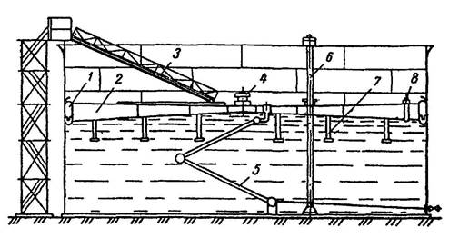
Vertical steel cylindrical tanks with a pontoon (RVSP type) are tanks similar in design to RVS type tanks (they have a stationary roof), but equipped with a pontoon floating on the oil surface (Fig. 12.22). Like a floating roof, the pontoons move along guide pipes 6, are equipped with support posts 9 and sealing valves 1, 7, and are carefully grounded.
Pontoons can be made of metal or synthetic. Metal pontoons are structurally little different from floating roofs. A synthetic pontoon consists of a stiffening ring with mesh, supported by floats and covered with a carpet of vapor-impermeable (for example, polyamide) film. Pontoons from synthetic materials Unlike metal ones, they are practically unsinkable, are installed in existing tanks without dismantling part of the roof or body, without the use of hot work in the tank, and require little metal consumption.
When constructing tanks of types RVS, RVSP and RVSPK, roll blanks factory-made bottoms and hulls.
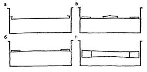
Rice. 12.21. Schemes of the main types of floating roofs: a - disk; b - single-layer with a ring box;
c - single-layer with annular and central boxes; g – two-layer
Rice. 1 2.22. Tank with floating metal pontoon:
1 - sealing valve; 2 - peripheral pontoon box; 3 - sheet metal membrane; 4 - screed; 5 - central pontoon box; 6 - guide pipe; 7 - guide pipe seal; 8 - manhole; 9 - supports for the pontoon; 10 - inlet and distribution pipe with clapper
Horizontal steel cylindrical tanks (RGS type)
Horizontal steel cylindrical tanks (RGS type), unlike vertical ones, are usually manufactured at the factory and delivered to finished form Their volume ranges from 3 to 100 m3. At oil pumping stations, such tanks are used as containers for collecting leaks.
Tank equipment
The following are installed on the tanks (Fig. 12.24):
Equipment that ensures reliable operation of tanks and reduces oil losses;
Equipment for maintenance and repair of tanks;
Fire fighting equipment;
Control and alarm devices.
![]()
Rice. 12.24. Layout of equipment on vertical tanks for low-viscosity petroleum products:
1 - skylight; 2 - ventilation pipe; 3 - breathing valve; 4 - fire fuse; 5 - measuring hatch; b - device for measuring level; 7 - hatch - manhole; 8 - siphon tap; 9 - firecracker; 10 - inlet-dispenser pipe; 1 - bypass device; 12 – firecracker control; 13 - extreme position of the receiving - distribution pipes in relation to the axis of the stairs; 14 - safety valve
Equipment to ensure reliable operation of tanks and reduce oil losses
This group of equipment includes:
Breathing fittings;
Inlet and distribution pipes with clapper;
Means of protection against internal corrosion;
Equipment for heating oil.
The breathing fittings of the tanks include breathing and safety 14 valves. The purpose of the breathing fittings is as follows. When tanks fill or the temperature rises in gas space the pressure in them increases. Since the tanks are designed for pressure close to atmospheric, they can simply burst. To prevent this from happening, breathing and safety valves are installed on the tanks. The first ones open as soon as the excess pressure in the gas space reaches 2000 Pa, the operating limit of the second ones is 5-10% higher, they insure the breathing valves.
Breathing fittings also protect tanks from collapse when the pressure in them decreases during emptying, or when the temperature in the gas space decreases. As soon as the vacuum reaches an acceptable value, the breathing valves open, atmospheric air enters the gas space of the tanks. If they throughput is insufficient and the vacuum continues to increase, the safety valves open.
Breather fittings are also the primary means of reducing oil loss from evaporation. Firstly, these fittings are in a normally closed state, which prevents ventilation of the gas space of the tanks. Secondly, the admission of a fresh portion of air into the tank (for saturation of which a certain amount of oil must evaporate), as well as the release of the steam-air mixture from it, does not occur at the moment of pressure change in the gas space, but with a delay determined by the operating limits of the breathing valves. Thus, the volume of “breathing”, and therefore the loss of oil, is reduced.
Inlet and distribution pipes 10 are used for receiving and pumping oil from tanks. At the ends of the receiving and distributing pipes, firecrackers 9 are installed to prevent oil leakage from the tank in the event of damage to the receiving and distributing pipelines and valves. The firecrackers on the dispensing pipes are necessarily equipped with a control system 12, which includes a cable with a drum controlled from the outside using a steering wheel, since otherwise it is impossible to pump out. The firecrackers on the inlet pipes are usually opened by the flow of injected oil.
Tanks always contain settled produced water. Its presence leads to internal corrosion of the bottom and first belt of tanks. To combat internal corrosion, water is periodically removed through siphon valve 8 and protectors are mounted on the bottom of the tank.
Equipment for maintenance and repair of tanks
For these purposes the following equipment is used:
Manhole;
Measuring hatch;
Light hatch;
Ladder.
Manhole 7 is located in the first belt and is used for penetration service personnel inside the tank. Through it, equipment that requires installation (protectors, pontoon parts, etc.) is also delivered to the reservoir, and bottom sediments are removed during manual cleaning.
Measuring hatch 5 is used for manual measurement of oil and produced water levels, as well as for sampling with a sampler.
Light hatch 1 is designed to provide access to sunlight inside the tank and its ventilation during flaw detection, repair and cleaning.
Metering and skylights are mounted on the roof of the tank.
Ladder 15 is used to lift personnel to the roof of the tank. There are the following types of ladders: leaning, spiral (going up the wall of the tank) and shaft. Stairs are wide Not less than 0.7 m and an inclination to the horizon of no more than 60", equipped with railings with a height of at least 1 m. At the point where the ladder is connected to the roof of the tank there is a measuring platform, next to which a measuring hatch is located.
Due to the relatively small volumes of annual sales, the total tank capacity for each petroleum product is usually small. Therefore, the unit capacity of tanks at oil depots is usually small and ranges from 100 to 5000 m3.
Tanks for storing petroleum products can be underground or above ground. Underground tanks include tanks whose highest liquid level is at least 0.2 m below the lowest planning level of the adjacent territory (within 3 m from the wall of the tank or from the walls of a building or structure). The remaining reservoirs are considered above ground.
The following types of tanks are used at oil depots:
- vertical steel;
- horizontal steel;
- reinforced concrete.
Vertical steel tanks
RVS type
Vertical steel cylindrical tanks with a fixed roof (RVS type) are the most common. They are a cylindrical body 1, welded from steel sheets measuring 1.5 × 6 m, thickness 4...25 mm, with a conical or spherical panel roof. When making the body, the long side of the sheets is positioned horizontally. One horizontal row of sheets welded together is called a tank belt. The tank belts are connected to each other in steps, telescopically or end-to-end.
The panel roof 2 rests on trusses and (for large-capacity tanks) on the central post 3.
The bottom of the tank 5 is welded, is located on a sand cushion, treated with bitumen to prevent corrosion, and has a slope from the center to the periphery. This ensures more complete removal of produced water.
Reservoirs of the RVS type are constructed with a volume from 100 to 100,000 m3. They are designed for overpressure of about 2000 Pa and vacuum of about 200 Pa.
RVSP type
Vertical steel cylindrical tanks with a pontoon (RVSP type) are tanks similar in design to RVS type tanks (have a stationary roof), but equipped with a pontoon floating on the surface of gasoline. The pontoons move along two guide pipes, one of which is simultaneously used for manual sampling (4), and the other serves as a sampler casing (5), equipped with a sealing valve 3, and carefully grounded.
The pontoons are a rigid gas-tight structure covering at least 95% of the surface of the oil product, equipped with an annular seal that seals the remaining surface.
Pontoons can be made of metal or synthetic. A metal pontoon consists of metal boxes of segments located around a circle and connected by metal flooring (carpet). The boxes are open (without a top cover) and closed type. Pontoons with boxes of the second type require more metal, but are also more reliable - they cannot be warped or even flooded due to oil products entering them through the top cover.
Synthetic pontoons are significantly less metal intensive. They are different in design. For example, a pontoon developed by VNIISPTneft (now IPTER) consists of a ring of rigidity on which a mesh is stretched, which serves as the basis for a carpet of gas-impermeable polyamide film. The buoyancy of this design is ensured by floats made of tile foam, chemically resistant to oil products. Synthetic pontoons made of polyurethane foam have also become widespread. They are assembled from pre-fabricated rigid polyurethane foam segments.
Regardless of the design, all pontoons must be grounded (to avoid discharges of static electricity), equipped with guides (to avoid rotation under the influence of jets of oil), as well as supports (to ensure the possibility of cleaning and repairing the tank, and also to prevent the pontoon from “sticking” to the bottom) .
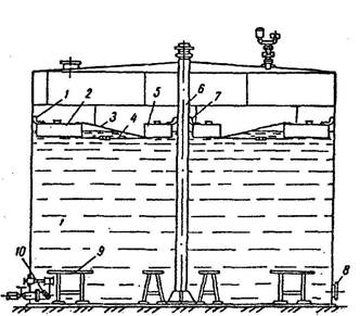
Type RVSPK
Vertical steel cylindrical tank with a floating roof (RVSPK type). The wall 4 of the tank is reinforced with stiffening rings 3, as well as an annular stiffening platform 5, which ensure the overall stability of the structure.
The floating roof consists of a flat central part and a peripheral ring pontoon 16 with sealed boxes. Each box has a 600 mm hatch on top, closed with a removable lid, which allows you to control the tightness of the welds during operation of the tank.
In the lowest position, the floating roof rests on support posts 8 (the RVSPK 50000 tank has 152 of them with a diameter of 89 mm). The racks are fixed to the floating roof and move with it. The height of the racks (1.8...2 m) makes it possible to carry out work in the tank under a floating roof.
To prevent it from turning when moving, there are two diametrically located tubular guides made of pipes with a diameter of 530 mm.
Horizontal steel tanks
Horizontal cylindrical tanks (RGS type) are a horizontally located cylinder with a flat or conical bottom. The tank body is constructed at the factory from steel sheets with a width of 1000 to 2000 mm. They are installed either underground (in dry soils with a depth of 1.2 m to the upper generatrix) or above ground (on supports made of precast reinforced concrete 0.8...3 m high and 0.3...0.4 m wide).
RGS type tanks are manufactured with a volume from 3 to 100 m3 and are designed for overpressure from 40,000 (for tanks with a flat bottom) to 70,000 Pa (for tanks with a conical bottom) and for vacuum up to 1000 Pa.
Reinforced concrete tanks
Reinforced concrete tanks (type ZhBR) are cylindrical and rectangular. The former are more common because they are more economical, although rectangular tanks are easier to manufacture.
Reinforced concrete tanks are usually made from prestressed reinforced concrete panels, the seams between which are sealed with concrete. Floor slabs rest on walls, and in some cases, on beams. The bottom is mainly made of monolithic concrete, 50 cm thick.
Cylindrical tanks of the reinforced concrete type are constructed with a volume from 100 to 40,000 m 3. They are designed for overpressure of about 200 Pa and vacuum of about 100 Pa.
Reservoirs of the reinforced concrete type require less metal consumption than steel ones. However, during their operation a number of shortcomings emerged. First of all, existing roof structures for reinforced concrete tanks do not have sufficient tightness and do not prevent the penetration of oil vapors from the tank into the atmosphere. Another problem is the fight against floating of tanks during high level groundwater. Finally, there are difficulties in repairing the internal equipment of reinforced concrete tanks.
Due to the above and a number of other reasons, reinforced concrete tanks are not currently being built.
Reservoirs of the RVSP and RVSPK types are used only for storing easily evaporating petroleum products, the RVS type - for both light and dark petroleum products, and the ZhBR type (existing) - only for dark ones.
| Tank farm capacity |


