To ensure the hydraulic stability of the ring gas distribution and gas consumption system (Fig. 3), the maximum permissible ring discrepancy of 5% was adopted in the calculation. From the calculation table. 11, it is clear that the maximum discrepancy is 3.7% (ring IV). In the remaining three rings, the discrepancy does not exceed 1.5%, which is a good achievement in engineering calculations.
10 Calculation of the pressure regulator of the gas control point
10.1 Theoretical basis for calculating pressure regulators
The hydraulic operating mode of the gas distribution and gas consumption system is controlled using pressure regulators, which automatically maintain constant pressure at the pulse sampling point, regardless of the intensity of gas consumption. When regulating pressure, the initial, more high pressure, to the final (lower).
The design of the pressure regulator includes regulating and reacting elements that ensure stable gas performance, and when gas consumption stops, the flow through the main valve is blocked. The main part of the regulating device is the sensing element (membrane), and the main part of the regulating device is the regulating body (the pressure regulator has a throttle body). Sensing element and the regulatory body are connected to each other by an executive connection.
The active drive force is the force that the membrane perceives from gas pressure P2, transmitted by impulse (through the tube). Next, the diaphragm force is transmitted to the valve stem. This force is usually called permutational N lane, it is determined by the following formula (25):
N lane = P 2 *F act, (25)
where: F act – active surface of the membrane, m2.
The active force is balanced by a spring N pr. The valve is also acted upon by the mass of moving parts N p.h. and the one-sided load N cl., which, neglecting the cross-section of the rod, is determined by formula (26):
N cl = f s *(P 1 – P 2) , (26)
where: f с – valve seat area, m 2;
P 1 and P 2 – gas pressures before and after the valve, MPa.
The balance of forces acting on the pressure regulator valve has the following form:
N lane – N springs – N p.ch + N cells. = 0 , (27)
The adjustment force depends on the amount of regulated pressure. If the value of P 2 becomes greater or less than the value to which the pressure regulator is set, then the balance of forces will be disrupted and the regulator will come into action. The process of pressure regulation will occur, i.e. regulation bandwidth pressure regulator.
The throughput of the pressure regulator depends on the area of the valve openings (seats), the pressure difference before and after the valves and the physical properties of the gas. In practical calculations, the pressure difference before and after the valve is usually taken as the pressure difference before and after the regulator. IN general case the amount of gas passing through the valve openings is determined by formula (28):
V =α*F*ω, (28)
where: V – valve capacity, m 3 /sec;
α is a coefficient that takes into account the loss of energy and narrowing of the jet in
valve holes;
F – area of valve openings, m2;
ω – speed of gas passage through the valve openings, m/sec.
Depending on the ratio of the gas pressure after the regulator to the pressure before the regulator, the speed (ω) has different expressions. For pressure ratios close to unity (with a pressure drop within 10 kPa), the gas is considered as an incompressible liquid. In this case, to determine the capacity of the regulator, use the following formula [ Tutorial Chebotarev and others]:
V g = 0.0125*(1/√ξ)*d 2 *√∆P/ρ g (29)
where: V g – productivity of the pressure regulator, m 3 / hour;
ξ – coefficient of hydraulic resistance of the pressure regulator;
d – diameter of the valve seat flow area, mm;
∆P – pressure difference before and after the regulator, kg/m2;
ρ g – gas density ( specific gravity), kg/m 3, at pressure P 1 and T 1.
(T 1 =273.16+ t g).
10.2 Calculation method for gas pressure regulator
Pressure regulators, regardless of the principle of operation, must ensure high stability of regulation, which is understood as such operation of the regulator in which the final pressure exhibits attenuation or harmonious non-damping of oscillations with a constant amplitude of small magnitude. If the final pressure oscillations occur with increasing amplitude, then the pressure regulation process is unstable.
Depending on the value of the ratio after the regulator to the pressure of the regulator, the gas velocity at the exit from the throttle body has different meanings, At small pressure drops in the regulators, the gas is considered as incompressible, i.e. the compressibility of the gas can be neglected.
For example: If ∆Р/Р 1 ≤ 0.08, then the error does not exceed 2.50%
When ∆Р/Р 1 > 0.08, the compressibility of the gas should be taken into account.
where ∆Р – pressure drop in the regulator on the throttle body (valve);
P 1 – pressure in front of the regulator valve, ata.
Provided ∆Р/Р 1 ≤ 0.08, the throughput (performance) of the pressure regulator is determined by the following formula:
V g = 0.00125*(1/√ξ)*d 2 *(√ ∆P/ρ g) (30)
where √ is the square root symbol; ξ is the coefficient of hydraulic resistance of the pressure regulator clan, taken within the range of 1.6 – 2. ρ g is the gas density, kg/m 3 .
If the pressure ratio ∆Р/Р 1 > 0.08, then an expansion coefficient is introduced into formula (30), taking into account the expansion of the gas as the pressure decreases.
ε = 1 – (0.46*(∆Р/Р 1)) (31)
V g = 0.00125*ε*(1/√ξ)*d 2 *(√∆P/ρ g) (32)
At critical or higher pressures, i.e. when equality is not respected.
P 2 /P 1 ≤ (P 2 /P 1) cr (33)
In this case, the capacity of the pressure regulator is determined
According to the following formula:
V g =20.3*(1/√ξ)*ε*d 2 *P 1 *(√ ((∆P/P 1) cr)/T*ρ g (34)
The pressure ratio P 2 /P 1 at which the gas flow becomes maximum and with a further decrease in pressure P 2 remains almost unchanged is called the critical pressure ratio. Consequently, when the gas pressure ratio Р 2 /Р 1 is equal to the critical one, as experience shows, the speed reaches its maximum - the speed of sound in a given medium and remains constant with a further decrease in the ratio Р 2 /Р 1 .
The critical pressure ratio is determined by the equation.
(P 2 /P 1) cr = 0.91*(2/K+1) κ/κ-1 , (35)
where K = C p / C v – adiabatic index (ratio of heat capacity at constant pressure to heat capacity at constant volume)
For example, for diatomic gases with κ = 1.4, the critical pressure ratio will be equal to:
(P 2 / P 1) cr = 0.91*(2/1.4+1) 1.4/1.4-1 = 0.482
This means that for diatomic gases with k = 1.4, the critical speed will be at the gas pressure ratio P 2 / P 1 = 0.482 and that a further decrease in the ratio P 2 / P 1 will not lead to an increase in speed.
Solution. Let us determine the critical pressure ratio for the source gas.
(R 2 /R 1 ) cr =0.91*(2/1.4+1) 1,4/(1,4-1) = 0.482
Actual pressure ratio for the first case. The calculation was performed in units of measurement - ata. R 1 = 1 + 1 = 6 ata; R 2 = 0.03 + 1 = 1.03 ata.
R 2 /R 1 = 1.03/2 = 0.515 > 0.482
Therefore, in in this case Formula (34) is applicable.
Thus, for the first case we will have the value φ = 0.486 (Appendix 5), and the gas density (specific gravity) at pressure P 1 and temperature T 1 , will be equal to:
ρ 1 = ρ * (R 1 T 1 /R 2 T 1 ) = 0.73 * = 1.42 kg/m 3
ε = 1 – (0.46*(0.97/2)) =0.777
Capacity for adopted pressure regulator
V G = 20.3*(1/√2.6)*0.777*(50)*2*(√(0.97/2)/(273.16+20)= 1990 m 3 /hour
The pressure regulator with a valve diameter of 50 mm adopted in the calculation provides a productivity of 1990 m3/hour at P1 = 1 kg/cm2 (0.10 MPa) and P2 = 0.03 kg/cm2 (0.003 MPa). The performance margin is:
δ =100*(1990 – 1968)/1968= 1.12%
The pressure regulator performance margin related to the settlement's estimated gas consumption is:
δ =100*(1990 – 1640)/1640 =22%, which is within acceptable values.
11 Hydraulic calculation of gas supply residential buildings
Two one-story residential buildings located at a short distance from each other are subject to gas supply. The plan and axonometric diagram of the gas network are presented in Fig. . At the same time, in residential buildings gas appliances are installed (PG-4; VPG-29 and AOGV-23). All calculations are performed in tabular form (table) in a certain sequence:
a) the numbers of sections are marked (fixed) on the axonometric diagram;
b) determine the estimated gas costs by area;
c) take the diameters of gas pipelines by section;
d) determine the sum of the coefficients of local resistance (for each section, the values of the coefficients ζ are selected from the table, appendix);
Rice. a) Gas supply plan for residential buildings; b) Axonometric diagram
gas network. 12; 2 – 3, etc. sections of gas pipelines.
e) from the graphs (Fig.) find the specific friction losses and equivalent lengths ζ = 1;
f) determine the design lengths of sections and pressure losses on them;
g) calculate additional overpressure gas in the pipe according to the formula:
∆Р = g*H*(γ in – γ g)
where: ∆Р – additional excess gas pressure in the pipe, Pa; N – difference in geometric marks of the end and beginning of the section, counting along the gas flow, m.
h) determine pressure losses in areas taking into account additional hydrostatic gas pressure;
i) determine the total losses in gas pipelines, taking into account losses in the pipe and fittings of the device (for example, VPG-29) up to gas burners. Approximate values of pressure loss in pipes and fittings gas appliances are: in gas stoves 40 – 50 Pa; V gas water heaters 80 – 100 Pa.
j) the resulting total losses are compared with the calculated gas pressure drop. If the need arises, recalculation is carried out by changing the diameters of gas pipelines in sections. The discrepancy should not exceed 5%.
Solution. plot 1 -2 – 3 – 4 in a private one-story residential building in which gas appliances are installed: PG-4; HSV-29; AOGV-23.
Table 12
Number plot | Name of devices (gas) | Quantity apartments | Coefficient simultaneity | Gas consumption m 3 /hour |
AOGV – 23 HSV-29; AOGV-23 PG-4; HSV-29; AOGV-23 PG-4; HSV-29; AOGV-23 AOGV-23 HSV-29; AOGV-23 PG-4; HSV-29; AOGV-23 |
We determine the estimated gas costs for sections of the gas supply system of two one-story residential buildings (Fig.):
V G = K O * V P * n, m 3 /hour
where: K O – the coefficient of simultaneous operation of gas appliances (apparatuses) installed in the apartment is taken according to the application.V P –gas consumption by one or more devices, m 3 /hour;n– number of installed devices.
Consumption natural gas 4 burners gas stove. Thermal output of four burners (application) is:
N P = 0.70 + 1.90 + 1.90 + 2.80 = 7.30 kW/h
The efficiency of a gas stove is: η = 56%.
V P = (N n *860*4.19)/ η * Q n , m 3 /hour
V P = (7 . 30 * 860 * 4 . 19)/0 . 56 * 35730= 1.30 m 3 /hour
Natural gas consumption by water heater VPG-29:
V V =(N V *860*4.19)/ Q n = (29*860*4.19)/35730 = 2.93 m 3 /hour
Natural gas consumption by the heating apparatus AOGV - 23:
V A = (N A *860*4.19)/ Q n = (23*860*4.19)/35730 = 2.30 m 3 /hour
Natural gas consumption by sections of the gas supply system of two residential buildings:
Section 1 – 2:V 1-2 = V 6-7 = K O ∙ V A ∙ n= 1∙2.30∙1 = 2.30 m 3 /hour
Section 2 – 3:V 2-3 = V 7-8 = K O ∙(V A + V V )∙ n= 1∙(2.30 + 2.93)∙1 =5.23 m 3 /hour
Section 3 – 4:V 3-4 = V 8-4 = K O ∙(V V + V A )∙ n=0.80∙(2.93 + 2.30)∙1 = 4.18 m 3 /hour
V 3-4 = K O ∙ V∙ n= 1∙1.30∙1 = 1.30 m 3 /hour
∑V 3-4 = 4,18 + 1,30 = 5,48 m 3 /hour
Section 4 – 5:V 4-5 = K O ∙(V V + V∙)∙ n= 0.46∙(2.93 + 2.30)∙2 = 4.80 m 3 /hour
V 4-5 = K O ∙ V∙ n= 1∙1.30∙1 = 1.30 m 3 /hour
∑V 4-5 = 4,80 + 1,30 = 6,10 m 3 /hour
Hydraulic calculation of the gas distribution system for gas supply of two one-story residential buildings (Fig.). The calculation is performed in tabular form (table). For a given gas pressure difference ∆P from node 5 to node 1, equal to 350 Pa. The average specific pressure loss in all areas is determined.
h Wed = ∆ P/ ∑ L p = 350/101.75 = 3.44 Pa/ linear meter
where: ∑L p – the estimated length of the gas pipeline sections, taking into account the surcharge for local resistance, m.
Hydrostatic pressure on vertical sections is:
N 4-5 = Z∙(γ V - γ G )∙ g= 1.50∙(1.293 – 0.73)∙9.81 = 8.28 Pa
Hydrostatic gas pressure at horizontal sections H = 0.
Analysis of the table shows that the total pressure losses in all sections connected in series are:
∑(h∙ L p + H) = 192.76 Pa
Table 13
plot | Calc. volume gas, m 3 /h. | Length part ka, m | Nadba VKA on local resistance | Rasche thin length L p , m | Avg.ud. sweat ri,h Wed | Uslo prominent dia. part. | Ud.by teri, h, | Resistance part h∙ L p | Hydr. pressure N G | Sum losses pressed hL p +H |
0 By By gas supply. 5. Works By Chebotarev Mikhail Alexandrovich; ... Aster of self-regulatory organizations based on the membership of persons preparing design documentation for capital construction projectsDocumentIntegration of urban planning and design"By control in the field... Works By project preparation internal systems gas supply. 5. Works By preparation... Federal State Institution Management "Rostovmeliovodkhoz" Chebotarev Mikhail Alexandrovich; ... Institutul de cercetări ştiinţifice în constricţii incercom fond de literatură tehnică chişinău – 2010DocumentI.F.Matsyuk Coursework and diploma designBy specialties: construction machines and... civil engineers 1977 G.P. Chebotarev |
1.6 Calculation of pressure regulators for ShRP
Currently, hydraulic fracturing units are constructed, as a rule, according to standard designs, or cabinet (block) hydraulic fracturing units are used in full factory readiness.
Therefore, the design of network hydraulic fracturing systems comes down to selecting the necessary pressure regulator and linking the corresponding one standard project or choosing the appropriate cabinet-mounted gas distribution unit.
The capacity of the pressure regulator is determined by one of the following formulas:
For the subcritical region of gas outflow
Q o =5260×K v ×ε× (17)
For critical mode gas outflow, i.e. subject to inequality
where Q o is the throughput of the pressure regulator, m³/h;
К v – regulator capacity coefficient;
ε – coefficient that takes into account the change in gas density when moving through the throttle body of the regulator;
Р 1 ÷Р 2 – absolute gas pressure before and after the regulator, MPa;
ρ o – gas density at normal conditions, kg/m³;
T 1 – gas temperature in front of the regulator, °K;
Z 1 – coefficient taking into account the compressibility of gas, at P 1 to 1.2 MPa is taken equal to 1.
The calculation is carried out in the following sequence.
The mode of gas movement is determined based on the initial and final gas pressure on the regulator.
The regulator flow coefficient is determined using formulas (17) and (18).
We select a pressure regulator that has a similar flow coefficient K v .
The throughput of the selected regulator is determined at the initial values of the initial and final gas pressure in front of it. The load on the regulator or the capacity reserve is determined in comparison with the performance of the ShRP. According to SNiP 42-01-2002, this reserve should be at least 15% - 20%.
Initial data for calculation:
The estimated productivity of ShRP No. 1, No. 3 is 101.8 m³/h, ShRP No. 2 is 22 m³/h, ShRP No. 4, No. 6 is 18.2 m³/h, ShRP No. 5 is 161 m³/h;
Gas pressure in front of the ShRP, 0.3 MPa;
Gas pressure after SHRP, 3 kPa.
For ShRP No. 1, No. 3.
P 1 =0.3+0.101=0.401 MPa; P 2 =0.003+0.101=0.104
Р 2 ÷Р 1 =0.104÷0.401=0.26, i.e. Р 2 ÷Р 1<0,5;
Therefore, further calculations are carried out using formula (18). Considering that a large pressure drop is activated at the regulator, the pressure losses in the ball-and-switch valve upstream of the regulator can be neglected. Next, we determine the regulator flow coefficient using (18)

Based on the obtained value of K v = 1.4, we select the regulator with the nearest larger value of this coefficient, RD-50, for which K v = 22.
Q o =5260×22×0.7×0.401×  =1300 m³/h
Determining the controller load
![]() %<80-85%
%<80-85%
Thus, the RD-50 gas pressure regulator accepted for installation has a sufficient performance reserve.
As noted above, cabinet-type hydraulic fracturing units are currently being produced in full factory readiness. Their passport characteristics are given in. Therefore, we will make further selection of pressure regulators according to the throughput shown in Table 3.22 in, according to.
For ShRP No. 2, we accept for installation a pressure regulator of the RD-32M type with a throughput capacity of 110 m³/h, the performance reserve of which is quite acceptable for our conditions.
Similarly, for ShRP No. 4, No. 6 we select RD-32M.
For ShRP No. 5 we accept the RD-50M regulator for installation.
2 Gas supply to the boiler room
2.1 Requirements for buildings and premises of gasified boiler houses
Buildings and premises of boiler houses with boilers operating on gas fuel are not explosive. Regardless of the floor where the boiler room is located, the rooms of smoke exhausters and deaerators must correspond to category G for fire hazard and not lower than the second degree for fire resistance. Under certain climatic conditions, it is permissible to install boilers in semi-open and open type boiler houses.
The addition of boiler houses, regardless of the fuel used in them, to residential buildings and buildings of nurseries and kindergartens, secondary schools, hospitals and clinics, sanatoriums, recreational facilities, as well as the installation of boiler houses built into buildings for the specified purpose is not allowed.
It is not allowed to place built-in boiler rooms under public premises (foyers and auditoriums, retail premises, classrooms and auditoriums of educational institutions, canteens and restaurants, showers, etc.) and under warehouses of flammable materials.
On each floor of the boiler room there must be at least two exits located on opposite sides of the room. One exit is allowed if the floor area is less than 200 m² and there is access to an external fire escape, and in single-story boiler rooms - if the length of the room along the front of the boilers is no more than 12 m. Exit doors from the boiler room must open outward. An exit is considered to be either a direct exit to the outside or an exit through a staircase or vestibule.
The installation of attic floors above boilers is not allowed. The boiler room floor level should not be lower than the level of the area adjacent to the boiler room building, and should have an easily washable coating. The walls inside the boiler room should be smooth, painted in light colors or lined with light tiles or glass tiles.
The distance from the protruding parts of gas burners or fittings in the boiler room to the wall or other parts of the building and equipment must be at least 1 meter, and for boilers located opposite each other, the passage between the burners must be at least 2 meters. If a fan, pump or heat shield is installed in front of the boiler front, the free passage width must be at least 1.5 m.
When servicing boilers on the side, the width of the side passage must be at least 1.5 m for boilers with a capacity of up to 4 t/h and at least 2 m for boilers with a capacity of 4 t/h or more. In the absence of lateral maintenance, the width of the side passage, as well as the distance between the boilers and the rear wall of the boiler room, must be at least 1 m. The width of the passage between parts of boilers protruding from the lining (pipe frames, etc.), as well as between parts of the boiler and parts of the building (columns, stairs), work platforms, etc. must be at least 7 m.
Gas control units (GRU) are placed in the boiler room near the gas pipeline entry in the boiler room or in an adjacent room connected to it by an open opening. GRU equipment and devices must be protected from mechanical damage and from shock and vibration, and the GRU location must be illuminated. GRU equipment, which can be accessed by persons not involved in the operation of the gas industry, must have a fence made of fireproof materials. The distance between equipment or fencing and other structures must be at least 0.8 m. GRU fencing must not interfere with repair work.
2.2 Technological part
2.2.1 Thermomechanical part
The project provides for heat supply for the heating and ventilation needs of an industrial enterprise from a local boiler house.
Boiler house heating capacity 3 MW
Coolant hot water 95-70°C.
The detailed design was completed in accordance with current standards and regulations, and provides for measures to ensure explosion and fire safety during operation of the facility.
The boiler room is equipped with 3 water heating boilers of the KSVa brand.
The boiler delivery set includes:
1. Gas burner GB-1.2.
2. A set of KSUM controls included in the burner automation system. Nominal capacity of the boiler room is 3×1.0=3.0 MW.
The coolant for heat supply systems is water with parameters of 95-70°C.
The network is fed with water that has passed through the PMU (anti-scale magnetic device).
The magnetic water conditioner ensures a scale-free condition of heating surfaces under conditions that prevent boiling of water in boilers and pipelines.
Flue gases are removed by natural draft through metal flue ducts Ø 400 mm and a chimney Ø 600 mm H=31 m.
The throughput coefficient calculator is a two-way online tool that will help you calculate the throughput coefficient Cv based on specified parameters, or calculate the throughput value knowing the Cv coefficient. The capacity coefficient Cv was introduced into the calculations to facilitate the work of designers of hydraulic and pneumatic systems. With its help, you can easily determine the flow rate of the working medium passing through an element of pipeline fittings.
Below are the formulas that we relied on when compiling this calculator.
Calculation formulas
1. In relation to gas environment
1.1. Consumption calculation
Given:
If P2+1>0.5*(P1+1) then [norm. liter/min]
If P2+1<0.5*(P1+1) тогда 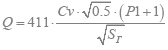 [norm. liter/min]
Given:
- inlet pressure P1 [bar]
- outlet pressure P2 [bar]
- flow rate Q [norm. liter/min]
- relative gas density Sg (relative to air)
If P2+1>0.5*(P1+1) then 
If P2+1<0.5*(P1+1) тогда ![]()
2. In relation to liquid medium
2.1. Consumption calculation
Given:
- inlet pressure P1 [bar]
- outlet pressure P2 [bar]
- capacity coefficient Cv ![]() [liter/min]
[liter/min]
1.2. Calculation of the required minimum Cv coefficient
Given:
- inlet pressure P1 [bar]
- outlet pressure P2 [bar]
- flow rate Q [liter/min]
- relative density of liquid Sl (relative to water) ![]()
Be careful when converting units of measurement. This can be done in
1.4 SELECTION OF GAS REGULATOR POINT EQUIPMENT.
The gas control point (GRP) is designed to reduce gas pressure and maintain it at a given level, regardless of changes in flow rate and gas pressure. At the same time, gas is purified from mechanical impurities and gas consumption is taken into account.
We are selecting equipment for hydraulic fracturing unit No. 3.
The gas control point (GRP) is one-story, I degree of fire resistance with a combined roof. The gas inlet and outlet through the outer part of the building in the casing and gas pipeline are installed with an insulating flange connection according to the 5.905-6 series. Natural and artificial lighting is provided. The GRP building has natural supply and exhaust constant ventilation, providing at least three times air exchange in 1 hour.
The main equipment of the gas control point is:
· Filter.
· Pressure regulator.
Safety shut-off valve (SSV).
Safety relief valve (SVR)
· Shut-off valves.
· Control and measuring instruments (instruments).
· Gas consumption metering devices.
In the thesis project, instead of a bypass gas pipeline (bypass), a second reduction line is provided, which significantly increases the reliability of the hydraulic fracturing operation. Installation of a safety shut-off valve is provided in front of the pressure regulator, and a safety relief valve behind the pressure regulator, on the outlet gas pipeline from the hydraulic fracturing unit. The gas control point is equipped with purge and discharge pipelines; they are routed outside at a distance of 1 to 1.5 m from the roof eaves of the building.
Gas control point GRP No. 3 was adopted on the basis of a standard design with a pressure regulator of type RDBK1-100, taking into account the gas flow rate of a chamber diaphragm of type DKS-50.
The selection of equipment for a gas control point is made based on the calculated load and the calculated gas pressure at the outlet and inlet of the gas control point. At the gas control point, the gas pressure is reduced to 300 mm. water st (izb).
The initial data for the calculation are:
- hydraulic fracturing productivity; Q = 2172 m 3 /hour
- gas pressure at the hydraulic fracturing inlet; P VX = 0.501 MPa (abs)
- gas pressure at the outlet of the hydraulic fracturing unit; P OUT = 0.303 MPa (abs)
- diameter of the pipe at the inlet to the hydraulic fracturing; D U = 57 mm
- diameter of the pipe at the outlet of the hydraulic fracturing unit; D U =273 mm
- barometric pressure Р B = 0.10132 MPa
To select a pressure regulator, we first calculate the required diameter:
Q – gas flow through the regulator, m 3 /hour
t – gas temperature, t = 5°С
V – gas speed, V = 25 m/s
Р М – pressure at the inlet to the regulator equal to 0.578 MPa (abs.)
 = 7.5 cm = 75 mm
We accept pressure regulator type RDBK1-100/50.
It is necessary to check the regulator for throughput, i.e. its calculated hourly maximum throughput Q MAX should be no more than 80%, and the calculated minimum throughput Q MIN should be no less than 10% of the actual throughput Q D at a given inlet pressure. In other words, the following condition must be met:
(Q MAX /Q D) ´ 100%£ 80%
(Q MIN /Q D) ´100% ³10%
where: Q MIN - minimum gas withdrawal by consumers, m 3 / h, taken equal to 30% Q MAX,
those. Q MIN = 630 m 3 /hour
Since P OUT / P IN< 0,9, то искомую пропускную способность регулятора при Р 1 = 0,501 МПа (абс.) определяем по формуле:
Qd =  , Where
f 1 = 78.5 cm 2 - cross-sectional area of the nominal bore of the regulator inlet flange.
P VX = 0.501 MPa (abs.)
j = 0.47 - coefficient depending on the ratio P OUT / P IN = 0.103/0.578 = 0.16 according to the graph in Fig. 9 we define j.
k 3 = 0.103 - the flow coefficient for RDBK 100/50 is determined from the table. 4 .
Qd =  = 3676 m 3 /hour
Checking the regulator load percentage:
 =
59,08 % < 80%
=
59,08 % < 80%
 =
14,8 % > 10%
=
14,8 % > 10%
Since the conditions are met, the regulator is selected correctly.
Calculation of hydraulic fracturing equipment.
table1.4.1
|
Determined value |
Calculation formula |
Result |
|
|
1. Absolute temperature of the medium flow, T |
T = T n + t = 273.15 + 5 |
||
|
2. Density of the gas mixture at t = +5 0 C, r n |
|||
|
3. Filter diameter, d y |
we assume equal to the nominal diameter of the gas pipeline |
||
|
4. Filter capacity, Q |
|
||
|
5. Pressure loss from filter installation, DP Ф |
|||
|
6. Excessive gas pressure after the filter, R F |
Р Ф = Р ВХ - ДР Ф / 10 6 = 0,49 - 7000 / 10 6 |
||
|
Diaphragm |
|||
|
7. Absolute gas pressure in front of the diaphragm, P A |
R A = R F + R B = |
Type DKS-50 |
|
|
8. Pressure loss from installing the diaphragm, DP D |
|||
|
9. Absolute gas pressure after the diaphragm, P pd |
R PD = R A - DP D = 0,5034 - 0,018 |
||
|
Safety shut-off valve |
|||
|
10. Diameter of nominal bore of the shut-off valve, d y |
We assume that it is equal to the nominal diameter of the filter |
||
|
11. Gas flow rate passing through the valve, Q |
|||
|
12. Excessive gas pressure in front of the valve, R I " |
R I " = R PD – R B = 0,4854 - 0,1034 |
||
|
13. Pressure loss from valve installation, DP CL |
|||
|
14. Excess pressure after the valve, P PC |
R PK = R I ¢ - R PK /10 6 = 0,4854- 65000 / 10 6 |
||
|
Pressure regulator |
|||
|
15. Pressure regulator |
accept type regulator |
RDBK1-100/50 |
|
|
16. Excessive pressure in front of the regulator, P PC " |
R PK " = R PK |
||
|
17. Calculated throughput, Q PR |
Q PR = 1595* 78.5 * 0.103 * 0.47 * |
||

|
18. Throughput coefficient, K P |
|
||
|
19. Initial controller capacity, Q 1 |
Q 1 = Q PR ´ K P = |
||
|
20. At Q MAX, the regulator load percentage |
|
||
|
|
||
|
Safety relief valve |
|||
|
22. Safety relief valve |
accept type: |
PSK-50N/0.05 lifting |
|
|
23. Compressibility coefficient, K 1 |
We accept |
||
|
24. Gas pipeline length: to the valve after valve |
|||
|
25. Sum of local resistance coefficients: to the valve after valve |
|||
|
26. Diameters of pipes |
D U = D U Fig. 22 |
||
|
27. Valve seat diameter |
|||
|
28. Required capacity of the PSK at 0 0 C and 0.1034 MPa, Q K " |
Q K " = 0.005*Q max = |
||
|
29. Required throughput under operating conditions, Q K |
|
||
|
30. Flow coefficient, a |
we accept |
||
|
31. Diameters of gas pipelines: to the valve after valve |
according to drawing |
||
|
32. Diameters of common gas pipelines: to the valve after valve |
|||
|
33. Equivalent lengths: to the valve after valve |
[6] nom. No. 6 |
||


|
34. Given lengths: to the valve |
L P = L VP + åx P *L DP = 3,5 + 3,38*1,5 |
||
|
after valve |
L С = L dс +åx С *L ДС = |
||
|
35. Gas pressure loss in the gas pipeline to the valve per 1 m length |
D Р¢п = 0.1*10 |
||
|
36. Absolute gas pressure in the gas pipeline to the valve + 15%, Р¢ ВХ |
P¢ IN =1.15*(P OUT – L P *DP¢/10 0)+P B =1.15*(0.003-8.57*1/10 0)+0.103 |
||
|
37. Gas pressure loss in the gas pipeline after the valve, |
DP C = 10 -6 *L C *DP C " DP C "= DP P " DP C = 10 -6 *35.2*1 |
||
|
38. Absolute gas pressure after the valve, P 1 " |
Р 1 " = Р ВХ " - ДР С = 0,1068 -0,0000352 |
||
|
39. Excessive gas pressure after the valve, P 0 " |
R 0 " = R 1 " - R B = 0,10236 - 0,099 |
||
|
40. Conditions for compliance of accepted diameters before and after the valve |
DP C< Р 0 " 0,0000352 < 0,00336 |
Condition met |
|
|
41. Critical pressure ratio, V KR43. Coefficient b for b > b KR 1790 |
|||
|
47. Number of valves, |
F C< F СК 399,86<1790 мм 2 |
1 class PSK-50N/0.05 |