Most craftsmen involved in private repairs of equipment sooner or later begin to think about how to assemble. Nowadays, equipment manufacturers offer a considerable number of such devices for use in small-scale production. This can be a device operating on alternating or direct current, a semi-automatic welding machine, or a device using electrodes. However, any good branded device costs big money, and its cheaper counterpart is usually unreliable and quickly begins to fail. For assembly welding machine first of all, you need to select or manufacture the necessary parts, this also applies to such a device as a throttle.
When creating a welding machine with your own hands, you need to pay attention to Special attention on the throttles.
The benefits of a choke for a welding machine
The welding choke is a regulator of the current used for welding. Its immediate task is to compensate for the missing resistance. It can be connected to the secondary winding of the transformer. This allows a phase shift between the passing current and its voltage, which makes it easier to ignite the electric arc at the beginning of the process. At the same time, it burns much more evenly, and this allows you to achieve sufficient High Quality weld seam. Without a choke, the current will always be at its maximum, which can create problems during the welding process.

Scheme semi-automatic welding machine.
The choke can be included in the design of both a welding machine, which uses electrodes during the welding process, and as part of a semi-automatic device. A semi-automatic welding machine that has it splashes much less metal during operation, the welding process itself is much smoother than without it, and weld at the same time it is boiled to great depth. So the advantages of using such a part are beyond doubt, and it can be installed not only on, but also on a similar factory-made device. This is especially true for inexpensive models that are prone to malfunctions. This will greatly facilitate the work on it and improve the quality of welding.
Return to contents
Options for using scrap materials
To make a welding choke yourself, you first need to find a suitable material. Many electrical devices that have reached the end of their service life and are discarded as unnecessary are quite suitable for this purpose. Since it is simply a core with a wire wound around it, there is quite a wide choice here. A transformer that was once part of the design of a device such as a tube TV may well be suitable for this purpose. The entire winding will have to be removed from it, and the freed core will be used to wind a new wire, the length and cross-section of which must be calculated in advance.

To create a choke, already used electrical devices are used.
You can also, if possible, use chokes that were on burnt out lamps street lamps. In this case, the old windings will have to be removed, since they have become unusable, but leave the cardboard spacers that created a gap between the main part of the core and the closing part. When winding a new wire, they will need to be put in their original place. In general, it should be noted that to wind the inductor, you can use any magnetically conductive core having a cross-section from 10 to 15 cm. In this case, it is necessary to create a non-magnetic gap between its parts, for which you insert an insulating gasket with a thickness of 0.5 to 1 mm.
Return to contents
Manufacturing technology and installation

Aluminum or copper wire participates in the creation of the throttle.
Aluminum or copper wire is used to wind the inductor. In the first case, its cross-section should be 35-40 mm, in the second, 25 mm will be sufficient. You can also use a busbar as a replacement for the wire, in particular a copper one, 4 by 6 mm, or a thicker aluminum one. In this case, the wire is wound in an amount of 25 to 40 turns, and the bus will need to be wound in 3 layers. If the above-mentioned part from a street lamp acts as the core, then winding is done only on one of the sides along the entire length until the window is completely filled. In this case, the winding direction cannot be changed. Each layer must be insulated from the previous one by laying cotton fabric, fiberglass or special insulating cardboard, which should also preferably be impregnated with bakelite varnish.
If the device is provided with not a smooth, but a step adjustment, then no air gap is made in the magnetically conductive core of the choke, and when winding through an equal number of turns, taps must be made. The contacts on them need to be strong enough, since they will bear a large load. In general, it must be recognized that installing a throttle has a positive effect on the operation of any welding machine, be it a semi-automatic welding machine or a primitive homemade one. For a device operating on alternating current, it will be optimal to use it together with a current rectifier, which will allow it to use almost the entire range of electrodes, and it will work much smoother.
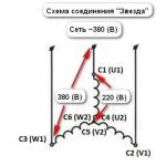
You can also install a choke on the device together with a step-down transformer. It is connected to the secondary circuit of the welding transformer. This replicates the design of a proprietary Japanese semi-automatic, which costs a lot of money. In this case, the throttle must be very accurately calculated according to the formula that is published in specialized literature, and this will give a considerable advantage. Such a device will have a transformer with good dissipation, and its characteristics will be clear.
It is worth immediately warning that before assembling a welding machine assembled on your own, the throttle must be correctly configured. This can be done in two main ways: by adding or unwinding the number of turns of wire, or by changing the size of the air gap in the core.
After the throttles have been successfully configured, homemade apparatus It may well work no worse than an expensive branded semi-automatic machine.
It will meet exactly the requirements that the owner needs.
Technical data of our semi-automatic welding machine:
Supply voltage: 220 V
Power consumption: no more than 3 kVA
Operating mode: intermittent
Operating voltage regulation: stepwise from 19 V to 26 V
Welding wire feed speed: 0-7 m/min
Wire diameter: 0.8mm
Welding current value: PV 40% - 160 A, PV 100% - 80 A
Welding current control limit: 30 A - 160 A
A total of six such devices have been made since 2003. The device shown in the photo below has been in service since 2003 in a car service center and has never been repaired.
Appearance of semi-automatic welding machine

At all

Front view

Back view

Left view

The welding wire used is standard
5kg coil of wire with a diameter of 0.8mm

Welding torch 180 A with Euro connector
was bought in a store welding equipment.
Welder diagram and details
Due to the fact that the semi-automatic circuit was analyzed from such devices as PDG-125, PDG-160, PDG-201 and MIG-180, circuit diagram differs from a circuit board because the circuit was drawn up on the fly during the assembly process. So it's better to stick wiring diagram. On printed circuit board all points and details are marked (open in Sprint and hover your mouse).

Installation view

Control board
A single-phase 16A type AE circuit breaker is used as a power and protection switch. SA1 - welding mode switch type PKU-3-12-2037 for 5 positions.
Resistors R3, R4 are PEV-25, but they don’t have to be installed (I don’t have them). They are designed to quickly discharge choke capacitors.
Now for capacitor C7. Paired with a choke, it ensures combustion stabilization and arc maintenance. Its minimum capacity should be at least 20,000 microfarads, optimal 30,000 microfarads. Several types of capacitors with smaller dimensions and higher capacity were tried, for example CapXon, Misuda, but they did not prove to be reliable and burned out.

As a result, Soviet capacitors were used, which still work to this day, K50-18 at 10,000 uF x 50V, three in parallel. 
Power thyristors for 200A are taken with a good margin. You can put it at 160 A, but they will work at the limit, they will require the use good radiators and fans. The used B200s stand on a small aluminum plate.

Relay K1 type RP21 for 24V, variable resistor R10 wirewound type PPB.
When you press the SB1 button on the burner, voltage is supplied to the control circuit. Relay K1 is triggered, thereby supplying voltage to the solenoid valve EM1 for supplying acid, and K1-2 - for the power supply circuit of the wire drawing motor, and K1-3 - for opening the power thyristors.
Switch SA1 sets the operating voltage in the range from 19 to 26 Volts (taking into account the addition of 3 turns per arm up to 30 Volts). Resistor R10 regulates the supply of welding wire and changes the welding current from 30A to 160A.
When setting up, resistor R12 is selected in such a way that when R10 is turned to minimum speed, the engine still continues to rotate and does not stand still.
When you release the SB1 button on the torch, the relay releases, the motor stops and the thyristors close, the solenoid valve, due to the charge of capacitor C2, still remains open, supplying acid to the welding zone.
When the thyristors are closed, the arc voltage disappears, but due to the inductor and capacitors C7, the voltage is removed smoothly, preventing welding wire stick in the welding zone.
Winding up a welding transformer
![]()
We take the OSM-1 transformer (1 kW), disassemble it, put the iron aside, having previously marked it. We make a new coil frame from PCB 2 mm thick (the original frame is too weak). Cheek size 147×106mm. Size of other parts: 2 pcs. 130×70mm and 2 pcs. 87x89mm. We cut out a window measuring 87x51.5 mm in the cheeks.
The coil frame is ready.
We are looking for a winding wire with a diameter of 1.8 mm, preferably in reinforced fiberglass insulation. I took such a wire from the stator coils of a diesel generator). You can also use ordinary enamel wire such as PETV, PEV, etc.

Fiberglass - in my opinion, the best insulation is obtained
We begin winding - the primary. The primary contains 164 + 15 + 15 + 15 + 15 turns. Between the layers we make insulation from thin fiberglass. Lay the wire as tightly as possible, otherwise it won’t fit, but I usually didn’t have any problems with this. I took fiberglass from the remains of the same diesel generator. That's it, the primary is ready.
We continue to wind - the secondary. We take an aluminum busbar in glass insulation measuring 2.8x4.75 mm (can be purchased from wrappers). You need about 8 m, but it is better to have a small margin. We begin to wind, laying it as tightly as possible, we wind 19 turns, then we make a loop for the M6 bolt, and again 19 turns. We make the beginnings and ends 30 cm each, for further installation.
Here is a small digression, personally, for me to weld large parts at such a voltage, the current was not enough; during operation, I rewound the secondary winding, adding 3 turns per arm, in total I got 22+22.
The winding fits snugly, so if you wind it carefully, everything should work out.
If you use an enamel wire as a primary material, then you must impregnate it with varnish; I kept the coil in the varnish for 6 hours.
We assemble the transformer, plug it into an outlet and measure the no-load current of about 0.5 A, the voltage on the secondary is from 19 to 26 Volts. If everything is so, then the transformer can be put aside; we no longer need it for now.
Instead of OSM-1 for a power transformer, you can take 4 pieces of TS-270, although the dimensions are slightly different, and I only made 1 welding machine on it, so I don’t remember the data for winding, but it can be calculated.
We'll roll the throttle
We take an OSM-0.4 transformer (400W), take an enamel wire with a diameter of at least 1.5 mm (I have 1.8). We wind 2 layers with insulation between the layers, lay them tightly. Next we take an aluminum tire 2.8x4.75 mm. and wind 24 turns, making the free ends of the bus 30 cm long. We assemble the core with a gap of 1 mm (lay in pieces of PCB).The inductor can also be wound on iron from a color tube TV like TS-270. Only one coil is placed on it.
We still have one more transformer to power the control circuit (I took a ready-made one). It should produce 24 volts at a current of about 6A.
Housing and mechanics
We've sorted out the trances, let's move on to the body. The drawings do not show 20 mm flanges. We weld the corners, all iron is 1.5 mm. The base of the mechanism is made of stainless steel.


Motor M is used from a VAZ-2101 windshield wiper.
The limit switch for returning to the extreme position has been removed.
In the bobbin holder, a spring is used to create braking force, the first one that comes to hand. The braking effect is increased by compressing the spring (i.e. tightening the nut).


There are a lot of inexpensive semi-automatic welding machines on the market that will never work properly because they were made incorrectly from the start. Let's try to fix this on a welding machine that has already fallen into disrepair.
I came into my hands with a Chinese Vita semi-automatic welding machine (from now on I will simply call it PA), in which it burned out. power transformer, just friends asked me to repair it.


They complained that when they were still working, it was impossible for them to cook anything, there were strong splashes, crackling, etc. So I decided to bring it to a conclusion, and at the same time share my experience, maybe it will be useful to someone. Upon first inspection, I realized that the transformer for the PA was wound incorrectly, since the primary and secondary windings were wound separately; the photo shows that only the secondary remained, and the primary was wound next to it (that’s how the transformer was brought to me).

This means that such a transformer has a steeply falling current-voltage characteristic (volt-ampere characteristic) and is suitable for arc welding, but not for PA. For Pa, you need a transformer with a rigid current-voltage characteristic, and for this, the secondary winding of the transformer must be wound on top of the primary winding.
In order to start rewinding the transformer, you need to carefully unwind the secondary winding without damaging the insulation, and cut off the partition separating the two windings.


For the primary winding I will use 2 mm thick enamel copper wire; for complete rewinding we will need 3.1 kg of copper wire, or 115 meters. We wind turn to turn from one side to the other and back. We need to wind 234 turns - that's 7 layers, after winding we make a tap.


We insulate the primary winding and taps with fabric tape. Next we wind the secondary winding with the same wire that we wound earlier. We wind tightly 36 turns, with a shank of 20 mm2, approximately 17 meters.

The transformer is ready, now let's work on the choke. The throttle is an equally important part in the PA, without which it will not work normally. It was made incorrectly because there is no gap between the two parts of the magnetic circuit. I will wind the choke on iron from the TS-270 transformer. We disassemble the transformer and take only the magnetic circuit from it. We wind a wire of the same cross-section as on the secondary winding of the transformer on one bend of the magnetic circuit, or on two, connecting the ends in series, as you like. The most important thing in the inductor is the non-magnetic gap, which should be between the two halves of the magnetic circuit; this is achieved by PCB inserts. The thickness of the gasket ranges from 1.5 to 2 mm, and is determined experimentally for each case separately.
- Options for using scrap materials
- Manufacturing technology and installation
Most craftsmen involved in private repairs of equipment sooner or later begin to think about how to assemble a welding machine with their own hands. Nowadays, equipment manufacturers offer a considerable number of such devices for use in small-scale production. This can be a device operating on alternating or direct current, a semi-automatic welding machine, or a device using electrodes. However, any good branded device costs a lot of money, and its cheaper counterpart is usually unreliable and quickly begins to fail. To assemble a welding machine, first of all you need to select or manufacture the necessary parts, this also applies to such a device as a choke.
When creating a welding machine with your own hands, you need to pay special attention to the chokes.
The benefits of a choke for a welding machine
The welding choke is a regulator of the current used for welding. Its immediate task is to compensate for the missing resistance. It can be connected to the secondary winding of the transformer. This allows a phase shift between the passing current and its voltage, which makes it easier to ignite the electric arc at the beginning of the process. At the same time, it burns much more evenly, and this allows one to achieve a fairly high quality weld. Without a choke, the current will always be at its maximum, which can create problems during the welding process.
Semi-automatic welding circuit diagram.
The choke can be included in the design of both a welding machine, which uses electrodes during the welding process, and as part of a semi-automatic device. A semi-automatic welding machine that has it splashes much less metal during operation, the welding process itself is much smoother than without it, and the weld seam is welded to a greater depth. So the advantages of using such a part are beyond doubt, and it can be installed not only on a homemade welding machine, but also on a similar factory-made machine. This is especially true for inexpensive models that are prone to malfunctions. This will greatly facilitate the work on it and improve the quality of welding.
Return to contents
To make a welding choke yourself, you first need to find a suitable material. Many electrical devices that have reached the end of their service life and are discarded as unnecessary are quite suitable for this purpose. Since it is simply a core with a wire wound around it, there is quite a wide choice here. A transformer that was once part of the design of a device such as a tube TV may well be suitable for this purpose. The entire winding will have to be removed from it, and the freed core will be used to wind a new wire, the length and cross-section of which must be calculated in advance.
To create a choke, already used electrical devices are used.
You can also, if possible, use chokes that were on burnt-out street lamps. In this case, the old windings will have to be removed, since they have become unusable, but leave the cardboard spacers that created a gap between the main part of the core and the closing part. When winding a new wire, they will need to be put in their original place. In general, it should be noted that to wind the inductor, you can use any magnetically conductive core having a cross-section from 10 to 15 cm. In this case, it is necessary to create a non-magnetic gap between its parts, for which you insert an insulating gasket with a thickness of 0.5 to 1 mm.
Return to contents
Aluminum or copper wire is involved in creating the inductor.
Aluminum or copper wire is used to wind the inductor. In the first case, its cross-section should be 35-40 mm, in the second, 25 mm will be sufficient. You can also use a busbar as a replacement for the wire, in particular a copper one, 4 by 6 mm, or a thicker aluminum one. In this case, the wire is wound in an amount of 25 to 40 turns, and the bus will need to be wound in 3 layers. If the above-mentioned part from a street lamp acts as the core, then winding is done only on one of the sides along the entire length until the window is completely filled. In this case, the winding direction cannot be changed. Each layer must be insulated from the previous one by laying cotton fabric, fiberglass or special insulating cardboard, which should also preferably be impregnated with bakelite varnish.
If the device is provided with not a smooth, but a step adjustment, then no air gap is made in the magnetically conductive core of the choke, and when winding through an equal number of turns, taps must be made. The contacts on them need to be strong enough, since they will bear a large load. In general, it must be recognized that installing a throttle has a positive effect on the operation of any welding machine, be it a semi-automatic welding machine or a primitive homemade one. For a device operating on alternating current, it will be optimal to use it together with a current rectifier, which will allow it to use almost the entire range of electrodes, and it will work much smoother.
You can also install a choke on the device together with a step-down transformer. It is connected to the secondary circuit of the welding transformer. This replicates the design of a proprietary Japanese semi-automatic, which costs a lot of money. In this case, the throttle must be very accurately calculated according to the formula that is published in specialized literature, and this will give a considerable advantage. Such a device will have a transformer with good dissipation, and its characteristics will be clear.
http://moiinstrumenty.ru/youtu.be/LvIyLUOzS64
It is worth immediately warning that before assembling a welding machine assembled on your own, the throttle must be correctly configured. This can be done in two main ways: by adding or unwinding the number of turns of wire, or by changing the size of the air gap in the core.
After the throttles are successfully configured, the homemade device will be able to work no worse than an expensive branded semi-automatic machine.
It will meet exactly the requirements that the owner needs.
moiinstrumenty.ru
DIY choke for a welding machine
Choke is the industrial name for an electrical element such as an inductor. This device has a wide range of applications, in particular, a powerful choke can be used to improve the performance of a semi-automatic machine or inverter for welding.
Principle of operation
The main property of an inductor, which is a magnetic circuit wound under certain conditions around a ferromagnetic core, is the stabilization of current strength over time. Simply put, voltage applied to the coil causes a smooth increase in current output. Changing the polarity leads to the same smooth decrease in current.

The main factor is the condition that the current passing through the inductor cannot sharply increase or decrease. This is precisely what determines the value of using a choke for welding - resistance compensation allows you to avoid sudden jumps in amperage. This allows you to protect against accidental burning of the workpieces being welded, reduce spattering of the melting metal and accurately select the current parameters for welding for a given metal thickness. Chances of getting good seam with the use of a choke for welding is much higher.
The parameter that determines the coefficient of change in current is inductance. It is measured in H (henry) - in 1 second at a voltage of 1 V, only 1 A can pass through a choke with an inductance of 1 H.
The number of turns on the coil directly affects the amount of inductance. It is directly proportional to the number of turns squared. But if you need to make a welding choke with your own hands, then it is not necessary to calculate the exact number of turns. Since the parameters of welding machines for household use are mostly standard and well-known, a welder will only need to use the instructions below to make a choke with his own hands.
Purpose
 In an inverter for welding, a choke is needed to create an electric arc on the electrode. Ignition occurs when a certain voltage level is reached. The welding choke increases the resistance, which shifts the phases between current and voltage and allows for smoother ignition. This fact in itself often allows one to avoid burning through the workpiece, especially if parts made of thin sheet metal are welded.
A smooth change in current makes it possible to avoid damaging the workpiece by abruptly applying too much power, to optimally set the arc temperature and, accordingly, to prevent metal spattering while maintaining the required processing depth.
Another valuable property is its partial protection against unstable voltage in the network.
Throttle for welding inverter significantly facilitates the ignition of the electrode, which should light up when more high voltage, than the inverter outputs.
An example is the MP-3 electrode, which must have a voltage of 70 V to ignite. An output choke for welding can make working with this electrode much easier for an inverter, which produces only 48 V at idle. This occurs due to the phenomenon of self-induction. The device induces EMF (electromotive force), which causes air breakdown and flashing of the welding arc, as soon as you bring the additive a few millimeters from the metal surface.
The choke for welding is connected to the secondary winding of the transformer in the machine. It can be used in devices of any type - both home-made and factory-made, operating on any principle - inverter, with a step-down transformer, and the like.
Materials for production
 The choke for retrofitting a semi-automatic device or inverter can be assembled with your own hands using structural elements from old technology- tube TVs, street lamps old design and other devices that contain a transformer.
Structurally, it consists of a core made of a material that conducts a magnetic field, but does not conduct electric current, or is reliably insulated, and three layers of windings separated by a dielectric. As a basis for the core, either a special material - ferrite, which has these properties, or a yoke (horseshoe) from an old transformer is suitable. Winding of the device for welding is done with aluminum or copper wire with a cross-section of 20-40 mm. If aluminum is used, the wire cross-section must be at least 36 mm; copper wire can be thinner. A flat copper busbar with a cross-section of 8 mm is suitable.
The dimensions of the core should allow the winding of approximately 30 turns of a busbar of a given section, taking into account the dielectric spacers. A core from the step-up transformer of the Soviet TV TCA 270-1 is recommended.
Sequencing
When necessary tools and the materials are prepared, you can begin to manufacture the throttle for welding. The algorithm of actions is as follows:
- disassemble the transformer, clean the coils from traces of old windings;
- make gaskets from fiberglass, cardboard impregnated with bakelite varnish, or other suitable dielectrics, which will subsequently play the role of an inductive (air) gap. They can simply be glued to the corresponding surfaces of the coils. The thickness of the gasket should be 0.8-1.0 mm;
- wind a thick copper or aluminum wire onto each coil. You should focus on a round wire made of aluminum with a cross-section of 36 mm or copper with a similar ohmic resistance. Each “horseshoe” is covered with 3 layers of 24 turns each;
- lay a dielectric material between the layers - fiberglass, cardboard impregnated with bakelite varnish or another dielectric. The gaskets must be reliable, since a choke of this design is prone to self-breakdown between windings. If the resistance between the windings is lower than the air resistance between the electrode and the additive, then a breakdown will occur between the windings, and the welding device will be irreversibly damaged.
Winding must be done evenly, without overlaps, strictly in the same direction, so that the “bridge” between the coils is on one side of the future inductor, and the input and output contacts are on the other. In case of an error, the jumper can also be installed askew. It is important that its installation turns coils with different winding directions into coils with the same direction in fact.
Power on and check
 The choke for welding is connected to the system between the diode bridge and ground - a contact that connects to the material being welded. The output of the diode bridge is connected to the input of the inductor, to the output of the assembled inductor - respectively, the ground contact.
The entire assembly for welding must be tested on a piece of metal of the same chemical composition and thickness, with which in the future it is planned to conduct most of welding work. Quality indicators are:
- easy electric ignition;
- arc stability;
- relatively weak crackling sound;
- smooth combustion without strong splashes of melt.
Please note that the introduction of this element into the design of the welding machine leads not only to stabilization of operation, but also to a slight drop in current strength. If the inverter or semi-automatic device begins to cook worse, it means that the current strength has dropped. The choke needs to be disconnected and a few turns removed from each coil. Exact amount turns in each specific case is selected empirically.
svaring.com
Using a welding choke
Almost every owner with the slightest bit of self-respect has a welding machine. As a rule, recently devices of relatively low quality have been purchased, which, after minor and inexpensive modifications, are absolutely not inferior to the best branded samples. One of these modifications is the installation of a choke for welding. 
What does this give? Firstly, the welding current is stabilized. When using an AC welding machine, ignition of the electrode is possible only when the voltage level required for ignition and the corresponding sinusoid are reached electric current. The inclusion of a choke in the design makes it possible to shift the phases between current and voltage, which leads to an easier start of welding work and more even combustion and, accordingly, a higher quality weld.
Welding chokes are used both in welding machines using electrodes and in semi-automatic machines. When used in a semi-automatic machine, metal spattering is significantly reduced, and the work becomes softer, and the seam is welded more deeply.
To make a welding choke with their own hands, craftsmen use transformers from old, preferably tube, televisions. To begin with, all the winding is completely removed, and the wire is wound onto the “hardware”, based on preliminary calculations.
It is worth noting that very good quality when making a welding choke with your own hands can be obtained if you use chokes from burnt out lamps as a workpiece street lighting. As a rule, the winding contains from 25 to 40 turns of wire, with a cross-section of 35-40 mm2 if aluminum wire is used and from 25 mm2 if it was possible to obtain copper wire. A shank, both aluminum and copper, is quite suitable for winding a choke.
So, you can install a choke on almost any welding machine, but experts still advise using it in conjunction with a rectifier unit - this only applies to welding machines operating with alternating current. In this case, a double goal is achieved. This results in softer operation and the ability to cook with any electrodes.
There are designs in which the choke is paired with a step-down transformer. In this case, the calculation of the throttle must be more accurate and is carried out using formulas that can be found in specialized literature.
With this implementation of the design, the preferred location for installing the choke is the secondary circuit of the welding transformer. It is worth noting that this is exactly how the choke is located in some expensive imported semi-automatic welding machines. The advantages here are obvious. With this arrangement, the transformer has normal dissipation and a very rigid external characteristic.
Adjusting the throttle is a very important task. Despite all the calculations, it is almost impossible to achieve stable and flawless operation the first time. Usually the number of turns is selected empirically unwinding or, conversely, adding turns. Another adjustment method is to change the air gap in the magnetic core - in this case the adjustment is smoother.
nanolife.info
Making a welding choke Please tell me what can I use to wind a welding choke?) How many turns and how? for home welding at 200 AThere is a choke in this circuit... I wish I had one)
Attached images
Manufacturing a welding choke Its parameters are not rigidly fixed. A core of 50-70 cm is enough, and the wires have approximately 40-60 turns, just to withstand the current. You can use additional trance windings. If there are very few turns, there will be no effect, if there are many, you will be tortured to extinguish the arc. Threat. It’s true that I don’t use a condenser - and that’s how it all works.Manufacturing a welding choke
Manufacturing a welding choke
We take iron from a 2-4 kW engine, and cut it with a grinder with a 2-2.5 mm stone across one side, this will be a magnetic gap into which to glue textolite onto the epoxy, all the grooves under the previous winding must be cut out with iron, if there are metal staples, then remove them, wrap it with insulation and twenty meters of 30 sq mm wire to help you.
Manufacturing a welding choke
FOREvERz (Apr 7 2010, 17:33) wrote:
why use the core?)
So that the inductance is high! Manufacturing a welding choke
According to reviews, the engine does not roll, that is, of course it will work, but TOP is better. And so look for a collapsible trans of 2 kilowatts and wind a copper busbar. In our argon welding choke the size was equal to the power trance.
Making a welding choke, is it possible to use a smoothing filter consisting of a capacitor and resistance without a choke? If so, what should the capacitor and resistance parameters be? Is it possible to use something like a rheostat instead of resistance? If so, what kind of rheostat?
Manufacturing a welding choke
Maybe we'll start with the horse......Which welding requires a choke? I did it for welding in argon, but later it turned out that it was quite possible to do without it..
Making a welding choke for conventional arc welding, supports electrodes from 2 to 4 mm. There is a rectifier, no filter, no choke. a We want to cook with stainless steel, etc. Making a welding choke And at one time I installed such a snail...
http://www.uralelekt...0bf/rtt_038.jpg
Manufacturing a welding choke
There is a rectifier, no filter, no choke. a We want to cook with stainless steel, etc.
Is that so? Manufacturing a welding choke
Is it possible to use a smoothing filter consisting of a capacitor and resistance without a choke?
This filter does not smooth out what is needed, which is why it is useless when welding. Making a welding choke The choke doesn't smooth out here! It maintains continuity of current, roughly speaking. These are different things. Or rather the same but it works differently.
Making a welding choke :(
Attached images
Making a welding choke, the resistor will be the welding arc..., and the more capacitors the better, the voltage of the capacitors is at least 100V, and the capacitance is as much as the welder’s body and your wallet will allow... When tying capacitors, take into account Kirgoff’s second law, or tie everything with a thick wire. .. The approximate total capacity is 200,000 - 500,000 microfarads, although you can also insert a resistor so that the capacitors do not remain charged after disconnection, 1 kOhm.Manufacturing a welding choke
Would it be possible to assemble a rectifier for welding using this diagram? electrodes 3 mm approximately. If so, what are the parameters of the capacitor and resistor? Does anyone know?
You can assemble it, but it’s no use; you won’t be able to cook it with a stainless electrode without a choke. Manufacturing a welding choke
cimon (Apr 12 2010, 22:10) wrote:
You can assemble it, but it’s no use; you won’t be able to cook it with a stainless electrode without a choke.
Of course, I haven’t tried it, but with an oscillator it will probably burn like a darling. The four SSSIs on alternating current were burning like crazy, and it seemed to be 80A. Manufacturing a welding choke
Of course, I haven’t tried it, but with an oscillator it will probably burn like a darling. The four SSSIs on alternating current were burning like crazy, and it seemed to be 80A.
What I haven’t tried is cooking with a stainless electrode with an oscillator, variable speed, and I haven’t even heard of it, it’s possible and it will be, why not. Only one question torments me: why do they cook everything constantly and not alternating with an oscillator? An oscillator is much easier and cheaper to make than a constant one. Two possible answers suggest themselves: 1. either weld with an oscillator, MMA welding, it’s extremely dangerous, because you won’t have to run around turning off the oscillator every time you change the electrode. 2. or the quality of the seam suffers. Manufacturing a welding choke
Would it be possible to assemble a rectifier for welding using this diagram? electrodes 3 mm approximately. If so, what are the parameters of the capacitor and resistor? Does anyone know?
Approximate total capacity 200,000 - 500,000 microfarads
Just don’t be surprised if after the first strike with an electrode on the part, a crater forms in it, and the electrode itself settles on the mask in an even layer of splashes... Making a welding choke A specific question was asked about how to make a welding choke yourself. I think the question is of interest to many, including me. I read on the forum that the throttle can be made from an old LATR, a motor from washing machine, an old trance, and maybe something else at hand... I would like not to start a flame and not go off topic somewhere into the abyss of the Galaxy, but still find out how and who made a homemade throttle (with sketches of drawings, photos, and don’t just make a cut and glue the textolite... where did you cut, where to glue?). It would also be more precise to provide the winding data - what and how to wind, how to insulate. Still, 30 squares is not 0.75mm. How to externally design the throttle? So that those who want to assemble the throttle on their own can choose the appropriate material and repeat. If you feel sorry for sharing your know-how, then it’s better not to write anything at all. And for those who want to discuss what catches their eye, but not on this topic, please go to other relevant subsections.
Almost every master has at least once thought about how to make a choke for a welding machine with his own hands. Quite a large number are sold today various devices, which can be used in small production conditions. This can be a device that operates on temporary or continuous current, a semi-automatic welding machine, or a product using electrodes. However, a high-quality device is very expensive, and budget analogues quickly become unusable.
Diagram of an AC welding machine with a separate choke: 1 – primary winding, 2 – core, 3 – secondary winding, 4 – choke winding, 5 – fixed part of the choke core, 6 – moving part of the choke core, 7 – screw pair, Dr – regulator current
For assembly homemade device For welding, you will need to select and build all the necessary elements, including the throttle.
Benefits of using a throttle

Single-phase bridge rectification circuit (a). Graphs of voltage and current in the transformer (b), voltage and current in the load (c).
A welding choke is a device for regulating the current used to perform welding work. The element is needed to compensate for resistance that may be lacking. It can be connected to the re-winding of the transformer structure. This makes it possible to shift the phases between the passing current and its voltage, as a result of which it is easier to ignite the electric arc at the beginning of work. It will burn evenly, and therefore it is possible to obtain a welding seam good quality. If you do not use the choke, problems may occur during welding.
The choke may consist of a semi-automatic design or a welding device that involves the use of electrodes. A semi-automatic machine with a throttle practically does not splash metal during operation. The welding process will be much smoother than without a choke. The weld seam can be welded to a significant depth. The advantages of such an element are beyond doubt. It can be mounted not only on homemade device, but also for the adaptation of factory production. Especially it concerns budget options prone to malfunctions. This can significantly facilitate work on such structures and improve the quality of the weld.
What available tools can be used

To build a choke for welding with your own hands, the first step is to prepare the material. IN in this case You can use almost any unused electrical devices. The design is an ordinary core with a wound wire. For this purpose, you can use a transformer structure that was previously mounted in an old TV. The entire winding will need to be dismantled. The core can be used to wind wire, the length of which is calculated in advance.
If possible, you can use parts that were installed in the lantern bulbs. Old windings should be dismantled, as they are often faulty. During the process of winding the wires, they will need to be installed in their original place.
To wind the inductor, you can use any core with a cross-section of approximately 12-15 cm. You will need to make a non-magnetic part between its elements. To do this, attach an insulation gasket approximately 0.6-1 mm thick.
Smooth current regulation can be achieved through the installation of movable windings of a transformer design. By changing the distance between the windings, you can change the magnitude of the magnetic flux and resistance in the repeat winding.

To weld with continuous current, an element must be connected to the winding at the output of the transformer structure to convert the temporary current into a continuous one. This device is called a rectifier. The current may not be continuous, but pulsating. It is possible to reduce ripple only by increasing the capacitance of the capacitor device.
To be able to adjust the arc current using a choke, 3 rectifiers must be connected between the output of the transformer structure and the point.
Elements that will be needed to construct the throttle:
- electrical design;
- wires;
- transformer;
- lantern lamp;
- cardboard for insulation.
How to make a choke for a welding device

Before winding the wire, you will need to insulate the yoke. To wind the choke, you can use aluminum or copper wire. In the first case, its cross-section should be approximately 36-40 mm, in the second, the recommended cross-section is 25 mm. Instead of wire, you can use a copper busbar 4-5 mm thick. If you plan to use an aluminum part, it must be thicker. The wire needs to be wound in an amount of 30-35 turns, the bus is wound in 3 layers. If an element from a lantern light bulb is used as the core, then winding should be done only on one side part along the entire length until the window is filled. The winding direction cannot be changed. Each layer must be isolated from the previous one. It is recommended to impregnate the elements with bakelite varnish.
During the winding process, taps should be made through the same number of turns. The contacts must be strong, since they will bear a significant load.
Installing a throttle has a positive effect on the operation of a semi-automatic device or an ordinary homemade device. For a device that operates on temporary current, it is recommended to use a device together with a structure for rectifying the current. In this case, it will be possible to use almost all possible electrodes.
A do-it-yourself choke for welding can also be installed on a device with a step-down transformer design. The element must be connected to the secondary circuit of the transformer for welding. This will make it possible to build a proprietary semi-automatic welding device, which is very expensive. The throttle should be accurately calculated according to the formula that is in the documentation supplied with the device. This product will have a transformer design with good dissipation and excellent performance.
It is important to configure the choke for an inverter or any other device correctly.
Stepwise adjustment of the welding arc current can be achieved by switching on an ohmic resistance at the output, which is a nichrome spiral, through the same number of turns of which taps should be made with contacts that can withstand any load. Flaw this method The problem is that in this case the thread will become very hot.
When the welding choke setting is successful, you can begin welding work.
Existing methods for adjusting welding arc current

You can adjust the arc current by changing the air gap. The transformer device can be in the following modes:
- Idling. Temporary voltage is applied to the input transformer device. In the repeat winding, an EMF is initiated, but there is no current in the output circuit.
- Load mode. In the process of igniting the arc, it will close the output circuit, which consists of re-winding the transformer device and the inductor winding. A current will flow, the value of which can be determined by the resistance of these windings. The degree of impact will depend solely on the size of the gap in the rod.
- Mode short circuit. The electrode touches the parts being connected. A temporary magnetic flux must be created in the core of the transformer structure. An emf should be initiated in the re-winding. The current in the circuit will be determined by the resistance value of the inductor and the winding of the transformer device.
The resistance will increase as the gap increases. This should lead to a decrease in magnetic flux. Eventually the arc current will increase. This method allows you to perform smooth adjustment current, so it is recommended to use it.
The disadvantage of the moving system is that if the metal vibrates, the coil will become unreliable during the passage of temporary current. In this case, the adjustment can be made in steps. To do this, the choke should be made so that there is no gap in the wire.
It is not difficult to build a welding choke with your own hands. To do everything correctly, you will need to follow the technology, prepare all the necessary elements and follow the sequence of actions.