After the first steel door was invented, installed at the entrance of the house, many began to think about how to protect their home from uninvited guests. Locks are structures for protecting premises that have been manufactured for a very long time. There are various types, configurations, operating features and similar differences, however, the essence of the mechanism remains completely unchanged, since the design is designed to block access to the room. Despite the fact that there are many modern technologies, installations such as a combination mechanical lock, the production of which began in the last century, continue to be popular. Initially they were installed on safes, and over time they were used in installing doors in ordinary apartments, garages, porches and private homes.
The design of combination locks is that they do not have a keyhole, due to which they become more reliable, wear-resistant and durable. The likelihood of hacking is significantly reduced. By installing a specific coding of the cylinders and rollers that make up the lock, you can customize the lock yourself, and installation can be carried out on doors made of various materials, for example: metal, plastic and wood. It is advisable that the door thickness be at least 3 cm, which will also complicate the burglary process for intruders.

Lock installation diagram front door do it yourself is very simple, because for this you need:
- Select a door locking mechanism relative to the width and thickness of the structure;
- Make a marking of the future location of the product;
- Using a drill, drill holes in the door to install the lock body;
- Install the code panel;
- Assemble the locking mechanism;
- Carry out installation and fixation of prefabricated parts of the mechanism;
Finally, you need to set up the code combination and check the functionality of the product.
How to make a combination lock: choosing a variety
To install a push-button door lock You will need to first select its type. They are: overhead and mortise. To install a surface-type lock, simply install it on the surface of the door, and the bar with the bolt located in it on the jamb of the door frame. Installation will not require more than 15 minutes. Installing a mortise combination lock can be quite a hassle and this is where it is required special attention and a smart approach.

As a rule, each magnetic door lock has instructions from the manufacturer, which must be followed as clearly as possible:
- A lock template is created, which is done by hand. Some manufacturers include it in the kit, and this greatly simplifies the installation process. Using chalk or a pencil, you need to apply markings to the door leaf. Thus, the location of the structure will be marked on the door on both sides.
- To make a niche on the door leaf for installing a lock, you can use a chisel or a special drill attachment.
- Next, holes are drilled to install the bolts.
- Where the crossbar is located lock design, you need to make a recess, and the dimensions must completely correspond to the front strip.
- After completing such work, the combination lock is placed in its rightful place and securely bolted.
- The face plate is being installed.
- Needed on door jamb make markings for mounting the locking bar, into which the bolt will be placed. To carry out this process, it is enough to lubricate one of the crossbars with chalk, due to which a mark will be made on the jamb.
- A recess is made in the jamb for the plank, and you also need to make markings for the holes in order to install it. The installation process fully corresponds to the installation of the front strip.
- Finally, you need to secure the counter or locking part of the lock.
Judging by the steps described above, we can conclude that installing a mortise combination lock is similar to installing other types of locks in the same way.
Combination lock repair
To make repairs on a structure such as a digital combination lock, it will not require too much effort, since basically renovation work consists in recoding the design. In addition, preventive recoding is periodically required to increase the safety of the product.

To change the code on the lock, partial disassembly of the structure is required to gain access to the buttons from the inside, for which you need to unscrew the cover with the buttons.
Next, you need to pay attention to the plates located inside, when pressed, the locking mechanism is activated, and each of them has a specially made cut. Visually separate the working and unused plates. To replace the code, turn the required plates in the opposite direction or, in other words, make other buttons active.
DIY invisibility lock
An electronic invisible lock is an additional device that can be used to increase the security of an apartment, house or any other premises. The electric lock is completely invisible from the outside, but inside it is reliable installation, capable of preventing intruders from entering. To make one like this electromagnetic lock with your own hands, you can use the most common car door actuator from central lock, and its control or, in other words, blocking is carried out through the most common signaling.
The essence of such an invisible thing is to block one keyhole bolt in the position when it is pushed forward:
- Due to the fact that the car anti-theft alarm device has enough wires, and a long type, it is possible to carry out competent and easy installation.
- It is necessary to select a place for subsequent installation of the actuator, since the pin that will be extended must fit exactly into the bolt when it is extended.
- Next you need to make precise markings on top bar door frame and it is drilled. Then a mark will be made on the crossbar, along which an additional through hole will be drilled.
- When the bolt is drilled into the hole, a countersink is made so that the actuator pin fits there as accurately as possible.
- Using the strip that comes with the kit, you need to secure the actuator to the door frame.
- Next on door frame a guide from 1 pin is installed, and a limit switch is installed so that it is triggered to open the door.
- It is mandatory to install the alarm unit, as well as all related elements located in decorative box made of metal. The box is installed on the wall surface next to the door with inside premises.
- The box closes tightly.
- An LED indicator or, in other words, an alarm system is connected to the doorbell button.
- The structure is ready for use.
If a power connection is required, this can be done using a stabilized unit, which has an output voltage of 12 V and a current of at least 1 A. To increase the autonomy of the device relative to the network voltage, you can use a battery from a car to power such a lock, which will be located in pantry or on the balcony.
We have added to our section useful homemade products for the home: do-it-yourself unpickable invisible lock.
Thieves have long learned how to open a mechanical lock of any complexity. It’s more difficult with a combination lock, but they find ways to bypass all its secrets.
However, you can open the lock only if you know the location of the unlocking device, for example a keyhole, door button, etc.
Realizing this, invisible locks without a keyhole and keys were developed, where the unlocking devices are made in the form of coded or infrared radio key fobs, GPS radiotelephones, etc.
It would seem that it is impossible to open such a lock. However, they open.
For example, they scan the key fob code with special devices. We have learned how to do everything, even rob ATMs by reading the code of a bank card.
In all these systems general disadvantage: the device (key, key fob, etc.) is concentrated in one place, which, having determined, the thief opens the lock.
Finding a key for it is not a problem, choosing a code too, the key fob can be scanned.
The proposed lock differs from the known ones in that the unlocking elements of the lock (hereinafter referred to as the keys) are spaced apart, duplicated many times, and the lock can only be opened when all the keys are activated.
Since the keys can be spread over a considerable distance, this lock is especially convenient for summer cottages, where thieves most often trade.
One of the keys can be placed, for example, in a separate toilet. It would never occur to anyone that by visiting the toilet, a person opened the house.
It’s hard to imagine how you can open such a lock without knowing the number, operating principle of the spaced keys and their location, especially since the lock itself is not visible from the outside of the door.
Design and principle of operation
The lock (Fig. 1) consists of a housing 1, in which a DC electric motor 2 DPR 42 12V is placed. 2500 rpm, which is connected by screw 5 to crossbar 3.
The screw thread pitch is 0.3…0.5 mm. At the nominal engine speed, the bolt moves 20 mm. in one to two seconds.
The lock closes and opens with a simple click.
The crossbar has an annular groove into which balls 8 fall when it moves. The balls serve as a transmission link between the crossbar and microswitches 6 and 7. The microswitches are designed to stop the engine. When the next ball enters the groove, the corresponding switch turns off the engine. The distance between the switches determines the stroke of the bolt. Pin 4 prevents the bolt from rotating.
 Fig.1
Fig.1
The lock control is shown in Fig. 2. The lock is open as in Figure 1.

Designations: P - 12v relay. with two changeover contacts kP1 and kP2. Bell button K5. Microswitches K2 and K3 operating in antiphase. When one is on, the other is off.
Electric motor M. Toggle switch K4. Reed switch GK. Blocking contact K1. circuits - 12v.
Closing the lock
To close the lock, you must close the door tightly. In this case, the previously open blocking contact K1 closes (Fig. 3)

Fig.3

Contact K1 is two metal plates attached to the door and one that closes on the door jamb. (Fig.4).
The contact prevents the lock from closing when it is open or not tightly closed. After closing the door, you need to press the K5 button located on outside doors. In this case, relay P is activated, transfers contacts KR1 and KR2 to the position shown in Figure 3 and turns on the engine M.
After one or two seconds, the motor will move the bolt to the position shown in Figure 5 and open contact K3. Relay P will be de-energized, contacts KR1 and KR2 will take a neutral position and turn off the engine. Fig.6. The castle will be closed.
 Rice. 5
After closing the lock, button 5 is disabled by contact K3. Any manipulations with this button that may interest a thief, long presses or even broken wires will not prevent you from opening the lock and repairing the damage.
 Fig.6
Fig.6
Opening the castle
To open the lock, you need to connect (short-circuit) circuit points A and B (Fig. 7).
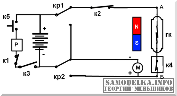 Fig.7
Fig.7
You can do this in various ways. For example, turn on the contact of the K4 toggle switch and bring the magnet to the main reed switch. (Fig.7).
The reed switch can be hidden under the door trim. Or use regular lighting as K4. If you screw in the lamp, the circuit will close. There are many options. There is a wide field for imagination here. Only one thing is important. It is necessary to place the keys (series-connected elements) farther away and, if possible, disguise them.
The opening phase of the lock is shown in Figure 7. After turning on the engine, the bolt that has moved to the open state (Fig. 1) will open contact K2 and turn off the motor.
 Fig.8
Fig.8
Now you can open the door by opening contact K1. The circuit returned to its initial state (Fig. 2). By closing the door and pressing K5, you can close the door again according to the algorithm described above.
Note
For proper operation lock, the direction of rotation of the motor must be consistent with the direction of the thread of screw 5. For a right-hand thread, in the opening phase of the lock, the motor must rotate counterclockwise when viewed from the shaft.
The article will tell you about the designs of electronic locks available on the market, from it you will learn the principle of operation of locking mechanisms, the types of electronic lock control systems used. Reading will help you do right choice electronic lock.
The use of electromagnets and servos has made it possible to change the understanding of the design of locks. A new generation of locking mechanisms uses a commanded electrical impulse (usually 12 VDC) to move the bolt or create clamping force. This made it possible to use electromechanical locks in the locking part of the door, which differ in design from classic mechanical locks, which generally increases the security of the home from entry by unauthorized persons.
With the help of microprocessor control systems associated with electromagnetic or electromechanical locks, access to the premises of a certain circle of people is easily organized, remote control door locking mechanism or opening the door without a classic key. All this is almost impossible to implement using standard mechanical locks.
Due to the simplicity of their design, electromagnetic and electromechanical locks are able to safely withstand tens of thousands of opening and closing cycles, which is beyond the capabilities of conventional mechanical locks.
Based on the principle of organization of the locking mechanism, modern electromechanical locks can be divided into the following main groups:
- Electric deadbolt locks.
- Invisible locks.
- Electric motor locks.
- Electric latches.
- Electromechanical locks.
Based on the control systems installed in them, locks can be divided into four types.
Radio controller

These systems can recognize both specialized key fobs and operate on standard frequencies of Wi-Fi or Bluetooth networks. In the latter option, a standard tablet or smartphone can be used as a “key”.
Code keyboards

The simplest and most common technical solution for electronic lock control systems. To activate the lock mechanism, you only need to enter a specific code, so there is no need to additionally purchase different types of keys.
The main “disease” of this control system is the erroneous operation or failure of the digital remote control keys, which is due to the peculiarities of its design. Over time, the contact plates oxidize and may not close the contact or distort the supplied signal, which leads to erroneous operation of the buttons. Therefore, all locks with keypads require regular maintenance.
Contact key controllers

One of the most common solutions on the electronic lock market. The lock allows you to store a certain number of contact keys in the memory, made in the form of a key fob or a plastic card with a magnetic strip. The system has high degree reliability.
Proximity key controllers

This system allows you to work with special radio-magnetic cards, which are activated remotely (at a distance of 10-15 cm from the reading device).
Electronic lock combining control using a code, contact key and radio key fob
Let us consider in detail all types of electronic locks, their advantages and disadvantages.
Electromagnetic locks
Electromagnetic locks are less similar to classic mechanical locks than other electronic locks. They consist of three main parts:
- Electromagnet plates.
- Reciprocal metal plate.
- Control systems.

These electronic locks are widely used as a locking mechanism on metal entrance doors. The microprocessor system that controls them operates both in intercom mode (reads and processes information from the keyboard and remote handsets) and analyzes information from contact keys.
Advantages
Thanks to the high reliability of the electromagnetic lock in combination with the significant force of attraction of the plate to the lock (50-500 kg), such a door guarantees a sufficient degree of protection of the premises from third-party penetration. The installed electromagnets and the outdoor part of the electronic lock control system are protected from moisture, which increases their reliability.
Electromagnetic lock 230 kg
After being disconnected from the power supply, electromagnetic locks can operate for a short time on a battery connected to the control system. After the battery is discharged, the electromagnetic lock will automatically open.
Flaws
The disadvantage of this system is the poor noise immunity of the communication lines of the control system with handsets installed in each apartment feedback, which can lead to the failure of the entire system during a severe thunderstorm.
Self-repair and installation of this system is rarely done, since it involves a large amount of work installation work followed by setting up the control system.
Electric deadbolt locks
This type of locks is similar in its appearance with a classic mechanical deadbolt lock. Can be completed various systems control, which ensures its versatility.

The system includes an electromagnetic bolt wire that can be used to both open and close the door. Some models, thanks to built-in spring return mechanisms, ensure automatic closing or opening of the lock in the event of a power failure.
Advantages
The electromagnetic mechanisms installed in these locks are highly reliable, significantly exceeding mechanical locks of similar class. A number of models are equipped with a door condition monitoring system, which eliminates spontaneous operation of the locking mechanism when it is open.
All models are easy to install and configure; installation and maintenance work does not require any special knowledge, which led to their high popularity.
Flaws
Inability to open the door if there is no power supply to the lock.
Since this lock consists of an electromagnet, return springs and electronic system control, its repair is reduced to checking the functionality of the magnet and the condition of the springs, and maintenance is limited to lubrication of moving parts and replacement of bushings and return springs. When the lock is equipped with a control system that works with contactless keys or with radio control, they can be used as “invisible locks”.
Invisible locks
This type of locks is specially designed for hidden installation. Both electronic deadbolt locks and compact latch locks can be used as these locks. Invisibility locks can be installed in different parts door leaf, or be built into standard mechanical locks, which significantly increases their resistance to burglary.

The lock comes complete with a control system that reads signals sent via a radio channel. Radio networks can be used as a signal source for opening and closing an electronic lock.
The lock is powered from a separate power supply (usually 12 or 5 VDC). Auxiliary battery power supplies are used to independently power the lock during a power outage. When purchasing an invisibility lock, you need to pay attention to the condition of the locking tongue, best option- when the tongue is initially retracted.
Important: if there is no power for a long time, the self-closing lock will not be able to be opened.
Advantages
This lock is quite simple in its design and contains minimum quantity working units, making it easy to set up and, if necessary, repair.
Flaws
Cannot be used as a separate locking mechanism due to the simplicity of the design.
Electric motor locks
This type of locks is no different in its capabilities from electric deadbolt locks. Its main difference is the use of a compact electric motor to move the locking mechanism.

A feature of some locks that use an electric motor as a driving element is their integration into a single control unit. Control units can process information both from the keypad and from various types of key fobs.
These electric motor locks are installed directly on classic mechanical locks with a cylindrical cylinder. With their help you can easily and with minimal costs time and effort to convert a classic mechanical lock, replacing the conventional lock cylinder with an electric motor one.
Example of an electric motorized invisible lock
Advantages
Low power consumption and, as a result, the possibility of long-term operation when powered by classic AA batteries.
Disadvantages also include the complexity of the mechanism, which requires regular maintenance, including maintenance of the locking mechanism, controlled by a mechanical and electrical drive.
Operating principle of an electromechanical lock
Ready-made solutions based on various types of electronic locks:
| Manufacturer, lock type | Locking mechanism type | Lock body type | Control | Price, rub. |
| ATIS LOCK electronic lock with contact keys | electromagnet and mechanical key | overhead | remote from intercom, contact key fob | 4000 |
| Electronic lock ATIS AM 280 on key fobs | electromagnet | mortise | 4000 | |
| Electric deadbolt lock AB700A on key fobs | electromagnet | mortise | remote from intercom, radio key fob | 4200 |
| Electronic lock ATIS AM 280 on cards | electromagnet | mortise | remote from intercom, card | 4600 |
| Universal coded electronic lock AM 280 | electromagnet | mortise | code keypad, magnetic key fobs, cards | 5730 |
| Electromechanical motor lock "Dori-4" Classic | electric motor | overhead | code dialing keyboard | 9370 |
Thanks to the simple combination of electric locks with various types control systems, you can create an access system of any complexity that provides high level burglary protection.
The ability to open remotely or process wireless radio signals of various frequencies by the control system and simplicity of design are the main advantages of electronic locks over mechanical ones. The simplicity of the design of actuators and the versatility of control systems increase the reliability of systems built on their basis.
It happens that random events force and mobilize to new ideas and creativity. What kind of radio amateur are you if you repeat everything and buy it ready? So it happened to me that I didn’t have to think long. And now the pockets are not loaded with excess cargo. It was winter, the key to the linen room broke, right in the lock. Attempts to remove the “stub” of the key were unsuccessful. I decided not to buy a new lock, but to remake the old one. In addition, three neighbors use the premises. While searching on the Internet for a simple combination lock, every now and then I came across circuits based on microcontrollers or several microcircuits. I needed to solve the problem simply and quickly. I decided to test the circuit based on the Johnson counter. What I found on the network was not suitable for repetition. The circuits were “raw”, non-working and did not have a time delay for holding the lock drive.
Electronic combination lock - circuit diagram
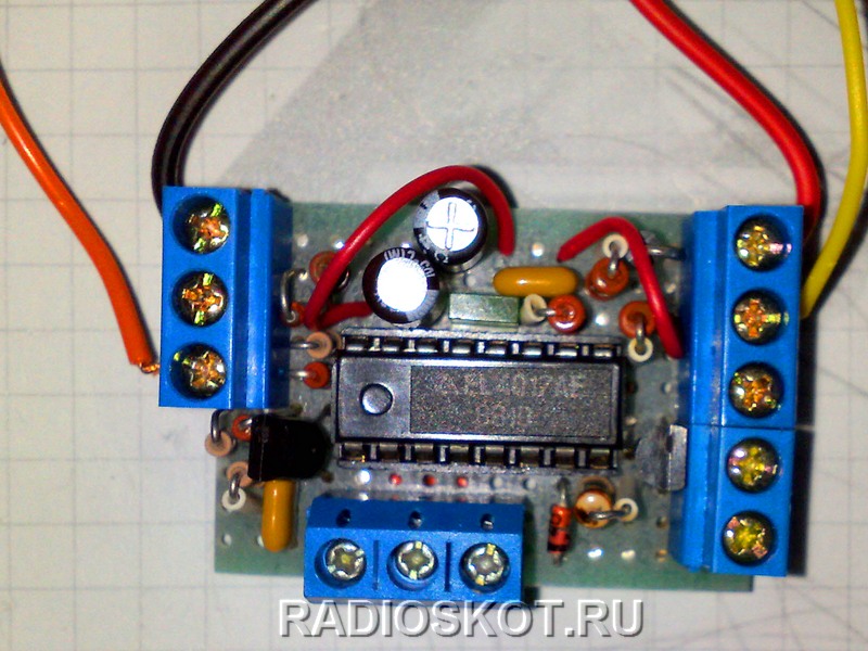
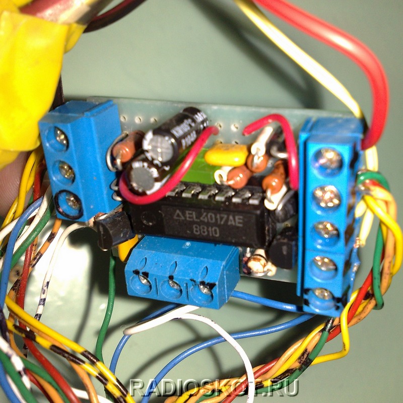
This scheme exists in different variations, and on different counters ( K561IE8, K561IE9, K176IE8, CD4022 and the like). I modified the circuit based on CD4017 (decimal counter divider with 10 decrypted outputs QO...Q9). Analogue microcircuit CD4017(Johnson counter) is K561IE8, K176IE8. I found a microcircuit with the designation EL4017AE, which I used in this device. When repeating a device, do not be lazy, identify the markings - they differ in characteristics (operating voltage). All necessary project files are .


So, the working of the electronic combination lock circuit is very simple. When the correct four-digit serial code is entered, a logical one appears at the output of the microcircuit (Q4), which leads to the opening of the lock. When you dial an incorrect number (buttons S5-S10), which is not part of the code, the circuit goes to its original state, that is, it is reset through the 15th pin of the microcircuit ( RESET). When S1 is pressed, a single state on the third pin Q0 of the microcircuit is supplied to the input of the field-effect transistor VT1; when it opens, it supplies voltage to pin 14 ( CLOCK) which switches the single state to the second pin Q1, then when the buttons S2, S3, S4 are pressed sequentially, the signal goes to Q2, Q3, and ultimately, when the correct code is entered from output Q4, the signal opens transistor VT2 to short time, determined by the capacitance of capacitor C1, including relay K1 which, with its contacts, supplies voltage to the actuator (electric lock, latch, or automobile “activator” (actuator)).
There is one thing, the code cannot consist of the same digit. For example: 2244, the values must be different, like: 0294, etc. Anyway, possible options There are a lot of codes, about one ten thousand, which is quite enough to use this combination lock in everyday life.
About the details of the combination lock
All radio components are cheap and can be replaced with other analogues. For example: VT2 can be replaced with the same npn transistor: 2N2222, BD679, KT815, KT603. To bypass the relay, it is better to use a Schottky diode. VD7 may not be installed, although it is better to have it to avoid polarity reversal (the voltage drop across it is not critical, since the circuit also works at 9V). Any relay with a lower operating current, 12V, with contacts designed for the lock drive current. Now about the design of the castle
The scheme is simple, tested, it has been working for a year and a half without problems, in hot and cold conditions. And most importantly, it’s easy to repeat! You buy radio components, you can use the circuit board.

As a drive for the lock, I used a simple automobile electric drive (actuator). The kit also includes fastenings - metal strips that need to be redone, as can be seen in the photographs. It all depends on what kind of lock is used for the renovation. You can install a ready-made electric strike from the company FASS LOCK Itemno:2369 (8-12V,12W). In this case, the capacitance of capacitor C1 is changed so as to obtain a time delay of 0.5-1s.

In my case, I attached a metal strip to the plastic handle of the lock, attaching it directly with self-tapping screws. From it to the drive, a spoke is put on (comes complete with the activator), and then the electric drive itself is also attached with self-tapping screws to the base of the door. The relay board is installed on the door and wiring from the keypad and power is supplied. As a body, I used plastic cover from under the coffee, drilling two holes for fastening.

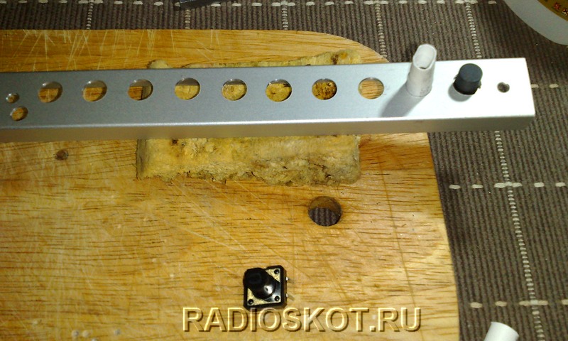

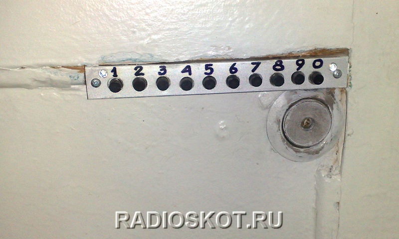
The keypad for dialing the code is made from the remainder of a U-shaped aluminum profile, for furniture facades, can be bought at any store furniture fittings. The profile is cut based on the number of buttons (10 pcs.). After this, you need to drill holes for the buttons, the diameter is slightly larger than the diameter of the button, so that the button with the cambric (tube) on it fits into the hole. This way it will be centered and, as a result, move freely when pressed, without jamming. This is done so that when filling the buttons with glue there is no mixing, but more on that later.

Filling buttons
It's time to secure the buttons in their place in advance. drilled holes. We insert the cambric into the buttons and put them in their place, as can be seen in the photo. Afterwards, you need to fasten them with drops of glue or hot melt glue. But this must be done carefully, so that there are no gaps left if the buttons are filled epoxy resin! Because my first panel, filled with epoxy, remained as a museum exhibit. The epoxy is very fluid and it seeped into the buttons and glued them together. Like this. I had to do everything anew and this time I filled the panel with hot glue. The buttons can be pre-glued, so as to secure them in place, with a two-component, instant glue used by furniture makers for gluing MDF, sold in the same place as aluminum profiles - in furniture fittings stores.

Of course, before pouring, you need to solder all the wires to the buttons and LEDs as you can see in the photographs. All this ensures a reliable, waterproof and non-removable keyboard, as well as beautiful design, which is applicable to any entrance doors, safes or garage doors. Also, the device can be used for security systems.

Now we drill two holes for screws to attach the panel. Also, one or two holes for LEDs (d=3mm). One of them (green light) on the right to indicate that the lock is open. The other one is not used, it can be connected to the power supply for a constant glow or through an additional button to illuminate the keyboard when it is pressed. Accordingly, the LED should be white (ultra bright), fixed so that the light flux is directed towards the buttons. You can cut another piece of the profile and attach it to the keypad on top, or even use a ready-made keyboard from a calculator or other devices. And if you make the front panel from plexiglass, then you will have a solution for illuminating the entire keyboard!

And lastly, the numbers can be applied ready-made, or you can draw them yourself using a felt-tip pen, and then cover them aluminum profile simple tape. This is done immediately after drilling the holes for the buttons. Of course, there are a lot of wires in relation to devices on microcontrollers, but not everyone has the opportunity to make such devices. The essence of this lock is that even a person who does not have any special skills in radio electronics can assemble it. I bought the parts, assembled it over the weekend, hung it up and connected it. All. This circuit does not require any adjustments. And yet, the code can be changed at any time. All wires from the keyboard are connected inside the combination lock body. Don't forget to label each wire. I used self-adhesive labels for price tags.
I would like to note that over the past time, there are no obvious signs of abrasion on the buttons! Most likely due to the black plastic. They are used daily. But it doesn’t hurt to clean and change the code from time to time.

Device power supply
The device is powered by an uninterruptible power supply from the company Dantom
. It has a built-in 12V/7A gel battery. You can assemble the same one, the circuit is very simple, it produces a constant small charging current (several milliamps with a fully charged battery, and 70 - 100 with a discharged one). This is enough to power several electric locks and electric strikes. Or make a smaller unit if you only have one door with a combination lock. Let's say: L7812CV, LM317, KR142EN8B. Also, the system can be powered from switching power supplies. 
Schematic diagram of power supply unit RIP


Printed circuit board BP RIP
In the proposed scheme backup source power supply (RIP), a moisture-proof transformer is used, but you can use any other 20-40 Watt, with an output voltage of 15-18 Volts. If there is only one car actuator under load, then a less powerful transformer will do. For several electric locks, the electrolytic capacitor C1 should have a higher capacitance than that indicated in the diagram - for a greater energy reserve when triggered and, accordingly, a smaller voltage drop across the load. Capacitor C2 – 0.1-0.33mF, C3 – 0.1-0.15mF. The radiator for IC1 is larger, about 100-150 cm2, since in a case with a battery, extra heating is not needed! The output load current for L7815CV is 1.5A. Moreover, if a plastic box is used as a housing, do not forget about ventilation holes. Diode D8 and fuse FS2 serve as protection against short circuit.


Security RIPs have a button ( tamper) against unauthorized hacking of the device - we won’t need it. On the board, to connect wires, it is better to use soldering instead of terminals, as the most reliable method of fastening. Also, it is appropriate to play it safe and take the spare power wiring out of the room, in case of an unforeseen event (stuff happens in life).
Video of a homemade lock in action
That's all, I hope you found it useful. ).
Discuss the article HOW TO MAKE AN ELECTRONIC CODE LOCK
Electric locks are modern locking devices that operate under the influence of electric current. Installation of electric locks in most cases is carried out by professionals, but all work can be done on your own. For installation and connection you will need minimum set tools, a lot of attention and maximum precision.
Additional devices for electric locks
The design of an electric lock depends on its type. Currently there are:
- electromechanical locks;
- electromagnetic locks.
Composition of an electromechanical lock
Combines the functions of a simple mechanical shutter and an electric drive.

An electric door lock with a mechanical opening function consists of:
- the housing of the device in which the electric motor is installed, a cylinder for opening with a key and locking bolts;
- strike plate;
- set of keys;
- additional electrical wires;
- fastening elements;
- instructions describing how to install an electric lock.

It is advisable to install electromechanical locks indoors or additionally protect them from moisture with casings.
Composition of an electromagnetic lock
Holds the door in closed position using a magnetic field that arises due to the supply of electric current, that is, a powerful magnet located in one part of the lock holds the metal bar located on the counterpart of the mechanism.

When purchased, such a device includes:
- a magnet, which is a separate part of the lock;
- a reciprocal metal strip attracted by a magnet;
- corner for attaching the main unit;
- fasteners;
- additional wires;
- instructions that describe in detail how to connect an electric lock.

Electromagnetic locks are less demanding than electromechanical ones. Use devices without additional protection Can be used both indoors and outdoors.
Additional equipment for any type of electric locks
Installation of electric locks on the door or is impossible without additional equipment, which includes:
- a controller that controls the electric lock and is located in a special unit;

- source uninterruptible power supply, which is required for the device to operate during periods of central power outages. The electric lock can be powered from electrical outlet or batteries located in this unit. The batteries are charged from the network adapter;

- reader of code information from a key fob or card, which is located on outside doors;

- door opening device from the inside. The electric lock on the front door can be equipped with this device for additional user convenience.

If the owner wishes, the electric lock for the gate can be equipped with an intercom with the function of autonomous opening from the living room. In this case, you won’t have to go outside every time to let visitors in.

Another additional device – a door closer – is installed at the user’s request. Doors equipped with closers operate smoothly, without vibration when closing, which reduces the service life of the lock.

Kit additional devices determined by the need (controller and power supply) and the wishes of the user.
Electric lock installation
Do-it-yourself electric lock installation is done in various ways, depending on the type of device and its location.
If a locking mechanism needs to be installed on a door, then mortise locks are predominantly used.

If a locking device is required to secure the gate, then rim locks are used.

Installation of an electric lock on the front door
How to install an electric lock on the front door? For this you will need:
- drill with various attachments for drilling holes for fastening elements of the lock and additional equipment;
- screwdriver for reliable fixation of connecting elements;
- chisel, hammer. Necessary for arranging an internal niche in wooden structures;
- boxes or other devices for protection electrical wires from mechanical damage and moisture, as well as to give the room an aesthetic appearance.
You can install an electric lock with your own hands according to the following scheme:
- on the door leaf, mark the area for installing the lock and mark the places where the device is attached;
Correct marking is the key correct installation and uninterrupted operation of the lock.
- remove part of the door leaf and drill holes for the connecting bolts;
- install the lock in the niche and securely fix the device;
- on the door jamb mark the area for the strike plate;
- remove part of the jamb in a similar way;
- install and secure the strike plate;
- install additional equipment;
The power supply is located near the current source. It is more advisable to install the controller on the wall next to the door so that the equipment does not interfere with the passage and opening of the door.
- stretch and put all connecting wires into boxes;
- connect all mechanisms. The electric lock connection diagram is included in the kit;
- connect the circuit to a power source;
- check functionality.
If errors or shortcomings are found, they should be eliminated and/or corrected, as the lock will not operate correctly.
Installation process mortise lock discussed in detail in the video.
Installation of an electric lock on a gate
To install an electric lock on a gate, in addition to the above equipment you will need:
- Bulgarian;
- welding machine.
This equipment is required for installation profile pipes on which the lock will be attached.

You can install the lock using the following instructions:
- if necessary, install a frame made of profile pipes in the area where the lock is installed. How to do this correctly will help you figure out the electric lock diagram attached to the equipment set, on which all the dimensions of the device are marked;
- make markings for further installation. It is necessary to mark the locations of fastenings and through holes required for installation of system elements;
- install and secure the lock;

- mount the strike plate and additional equipment provided for by the design in a similar way;
- connect the electric lock according to the attached diagram;
- install a protective cover over the lock;
- check the correct operation of the device. If necessary, correct shortcomings.
Installation of electric locks is carried out according to the diagrams attached to the device. In order for the mechanism to work correctly and be used for a long period of time, the entire installation process must be carried out with the utmost precision and special attention.


