After assembling and connecting the input panel with circuit breakers, installing the wiring with distribution boxes, it is time to install light switches. Correct installation These switching devices will not only rationally illuminate any area in the room, but also save energy.
Installation of any switch can be done by yourself. There are no restrictions in this regard in the legislation. However, there are “Rules for the construction of electrical installations” (PUE). Their observance inside the apartment supervisory authorities not checked, but for general security it is recommended to do them.
General principles for installing switches
If you don't mount complex system pass-through switches, there are only two main connection diagrams:
- Both lines are inserted into the switch body: phase and zero. A ready-made bundle of power conductors emerges from the switching device, which is directly connected to the lighting source. That is, the installation of the switch is actually combined with the installation of the distribution box.
With this method, the diagram is more understandable (especially for those who will subsequently maintain or upgrade the lighting system). However, from the point of view of cable consumption and the number of wires in the line (grooves, corrugations), such an approach is irrational.
Another drawback: you have to install contact blocks or twisted wires in the housing. Therefore, to implement the circuit, mounting boxes are required larger size(at least depth).
Despite certain difficulties, many homeowners choose this particular installation scheme. Firstly, it is convenient for implementing complex light switching schemes. Secondly, it is always possible to change the configuration without laying new lines. This is especially important when replacing the light point with a more “advanced” one.
In addition, the circuit with a direct connection to the power source (zero-phase) makes it possible to easily install lighting controllers, as well as RGB systems.
A prerequisite when creating such a diagram (it can be unique for each specific case) is to display the wiring in graphical form. Then it will be easier for the new owners of the premises to understand it. And over time, the owner himself may forget what he came up with at the time of connection.
- Remote switch. With this method, all wiring is done in distribution boxes, and only conductors are connected to the switch to open the line.

This is a standard diagram for typical wiring installation in finished apartments. The method is not mandatory, the PUE does not prescribe any specific installation schemes. The tradition dates back to the times of the USSR, when housing was state-owned, and teams of electricians had to save on everything.
In addition to saving wiring, there is another significant advantage: any electrician with a classical education will understand the standard circuit. In all typical Soviet-era buildings, the light connection is the same.
There are also disadvantages. At a minimum, additional distribution boxes must be installed: one for each switch. This spoils the aesthetics of the walls.

A more serious problem is difficulties with modernization. For example, installing an additional light source on the same line with the main one is impossible without laying a new line. In addition, a remote keyboard player cannot simply be swapped for an intelligent light level controller. With such a scheme, it is only possible to install primitive resistor (triac) systems, which simply dim the brightness without saving electricity.

Most often, a similar scheme is used when the installation of a single-key switch is required, which does not involve further modernization.
However, both methods have the right to life. The owner chooses the scheme based on the complexity of the lighting system and calculation of electrical costs.
Safety considerations when installing switches
The first rule is that the power of the switch must exceed the design load by at least one and a half times. The contact group can withstand a certain current. If it is exceeded, the metal will burn and the resistance will increase. In addition to the blinking light, the owner can expect more serious problems. Constant sparking in the housing can lead to melting of the switch, and even to its fire.

The quality of workmanship also matters. You should not choose products from little-known brands or switches made according to specifications. The packaging must be certified in accordance with GOST R 50345–2010 (IEC 60898–1), preferably ISO-9000. Cheap counterfeits use low-quality contacts that quickly wear out even under acceptable load.
The following criteria are not mandatory, but they also affect the safety of use:
- robust housing
- reliable fixation of the keys (they should not warp or fall out when switching)
- high quality wall mounting
Let's take a closer look at the last point. Almost all owners of old apartments have seen sockets falling out of the walls and switches dangling in boxes. IN best case scenario, such “freedom of movement” could lead to the contacts closing on the metal installation box, and in the worst case, in the dark you could get an electric shock.
Steel boxes have been installed before if you have old apartment- for safety reasons, they should be replaced with plastic ones. The problem is this: on any indoor switch there are two mounting options. Either with expansion anchors or using self-tapping screws. The first option was used in metal mounting boxes. Over time, the elasticity of the anchors is lost, and the stops do not hold the switching device in place.

In concrete walls panel houses There are already cylindrical seats for the boxes. Sometimes unscrupulous electricians ignore the installation of mounting boxes, securing switches to spacer anchors. This is a violation safe installation. On concrete or any other walls, first use construction mixture the mounting box is installed, then the switch is attached to it.

There are boxes for drywall and SIP panels. In any case, the body of the built-in switch is attached to the box using self-tapping screws.
Next important question- correct connection of the disconnected conductor. On the one hand, in 220 volt alternating voltage networks there is no polarity. Any electrical appliance will work regardless of which contacts are connected to zero or phase (we are talking about a single-phase household network). And if this issue is not relevant for the outlet, connecting the light switch is strictly regulated.
Important! Only the phase wire is supplied to the breaking contact (a group of contacts if you have two or three keyboard players).
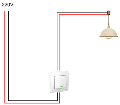
Let's consider typical installation single-key switch. Two wires are supplied to the lamp socket: zero and phase. Let's say you open the neutral wire using a switch. The light will go out, but there will always be a dangerous potential of 220 volts on one of the cartridge contacts. If you touch this contact while replacing the lamp, you will receive an electric shock. And this is with the device turned off!
Therefore, the neutral wire always goes directly to the light source, and the phase wire passes through the switch contacts.
In this regard, there is a positive " side effect» when choosing a circuit breaker installation scheme with the “zero” and “phase” inserted into the housing. Thanks to the “high competence” of electricians, it is possible to change the neutral and phase input to your home. You can change the so-called "polarity" on the input without changing the entire wiring configuration.
Ground switch
Despite the apparent absurdity, there are such models. In general, the grounding loop should not have disconnecting devices along its entire length. Therefore, the switch contacts with grounding do not intersect. Metal parts of the housing may be grounded: for example, the mounting substrate is often made of steel for strength. When installing internal switches in the bathroom (which is generally undesirable), or in places where moisture could potentially get on the housing, use protective grounding. If a dangerous potential of 220 volts occurs on the housing and a wet wall, a short circuit or current leakage will occur. The circuit breaker or RCD will trip.
Geometry of switching devices in the room
There are no strict rules for violation of which there are sanctions. You can place them as you see fit. For example, instead of installing a two-key switch, it is permissible to place two one-key switches side by side. However, there are standards adopted in the European Union and the Russian Federation, the implementation of which is recommended for your own safety.

Do I need backlit switches?

This is a convenient feature; you won’t have to fumble the keys in the dark. However, there are also side effects. Regardless of how the backlight is implemented (LED with a resistor or neon lamp), a small galvanic connection occurs between the phase and neutral wires. This does not affect safety, but some types of lamps may glow slightly when off.
Connecting two or three-key switches
If you do not have a lighting brightness adjustment system, it makes sense to connect a multi-arm chandelier in a combined way. For example, a two-key switch allows you to select 3 lighting levels (on a lamp with 6 lamps):
- first key - 2 lamps
- second key - 4 lamps
- both keys - 6 lamps

The connection diagram does not depend on the method of installation of the switch (see section “General principles of installation of switches”). A phase wire is supplied to the common contact, and the necessary groups of consumers are connected to the output contacts (2 lamps or 4 lamps on a chandelier).
When connected various sources light, the connection principle is the same, with the exception of the combined neutral wire. It must be separated into both light spots.
For example, using one three-key unit, you can turn on a chandelier with three levels of brightness (see description above) and a night light. In practice, switches with no more than two keys in one housing are usually used. The only exception is in the case of total space saving.
Proximity switches
For ease of use, switching devices are produced without mechanical keys. For example:
- sensory ones are triggered by a raised hand;

- acoustic ones turn on (turn off) the light by clap or voice command;
- switches with motion (presence) sensors also operate without mechanical contact.
There are also automatic switches that are triggered by a timer, or when an external command is given (phone call, SMS, or control using a computer application). True, the installation of circuit breakers must provide for the possibility of forced unlocking. In case the electronics fail.
Installation of a touch switch, as well as any other with a control circuit, from an electrical point of view installation work no different from ordinary “mechanics”. Power contacts are connected according to the same principle. Unless the “remote switch” circuit from the distribution box may not work.
But the control scheme may require a qualified approach. At a minimum, the control unit requires a separate power supply. This can be a built-in module in the housing, or a remote device that needs to be discreetly mounted nearby.
Automatic switches for lighting systems
Despite the fact that installing an automatic switch to power light points is practically not used, such a connection is acceptable to save equipment. In this case, a separate group of “automata” is allocated on the power panel, to which the lighting network is directly connected. The connection is made according to the standard scheme: the contacts open the phase.

Otherwise, when you turn off the light, you can mistakenly turn off power to an important node. If possible, such switches are placed in a separate panel.
The advantage of this method: the machines are designed for a higher load, and immediately include protection functions. The reliability of such devices is higher in comparison with household switches. The disadvantage is that when used in a residential area, such a switch does not look aesthetically pleasing.
Bottom line
As can be seen from the description, installing home switches is not difficult. In comparison, installation of a vacuum circuit breaker in production requires sophisticated equipment and qualified personnel. Special alloys and high-strength bolt ties are used.

And the contact groups of household electrical appliances are designed for direct connection of wires, without the use of special terminals.
Video on the topic
For experienced electricians no easier work than the banal installation of a switch. In fact, there is nothing super complicated in this operation. True, in addition to mandatory compliance with the rules outlined in the code for electricians of the PUE, knowledge of some subtleties is also necessary. They will tell beginners how to connect the light switch in their favorite bathhouse so that bath procedures took place in civilized conditions.
Competent choice of the “captain” of electrical wiring
We'll keep the rank of general for ourselves, because... The switch will serve under our command. We will assign the colonel to an old-style packet switch or a new two-pole circuit breaker installed in the power supply panel of a country property. The colonel will give an order to the captain while the device is connected to the electrical wiring in order to completely relieve the voltage.
Important! During the period of work with electrical wiring, the supply of current to the object being equipped must be completely shut off, i.e. relieve tension by disconnecting.
The device that gives commands to the light bulb under our supervision is selected according to the type of wiring available. It could be:
- open - laid on top of walls, mainly made of logs or timber;
- hidden - carried out in channels-grooves, hollowed out in brick, foam concrete, aerated concrete.
With open wiring, everything is extremely simple: the paths for the supply and exit of the electrical flow, as well as the connection points, are determined by the naked amateur eye. To install a bathhouse with hidden wiring, you will need an electrical circuit diagram, with the help of which you need to determine the point of possible installation.

Switches for hidden and open wiring differ structurally and externally:
- Hidden devices for switching on/off are located flush with the walls, delighting the owners only with a beautiful protective cover. The entire filling of the device is “recessed” into a pre-hollowed niche. The mechanism that gives the captain's commands is located in a dielectric socket, similar to a shallow plastic glass. This is what needs to be installed initially in the formed recess. Fix hidden socket boxes in plasterboard partitions With the help of special spacers, in brick and concrete walls they are “planted” on alabaster or mortar. Socket boxes for switches for hidden wiring are sold separately; they need to be selected depending on the wall material.
- Switches for an open electrical network are equipped with a flat plastic or metal platform instead of a cup-shaped installation device. It must be attached with galvanized screws to wooden wall, dowel-nails to brick or concrete.
Both switch options have an equal number of structural components. This is a socket box, a command mechanism and decorative and protective parts made of dielectric materials that prevent the passage of current. Read more about choosing switches on the Engineer's Advice website.


General principles and installation algorithm
Installation of both types of devices is carried out by analogy, they operate general principles and a single work algorithm:
- First, a socket box is attached, which is a bowl or platform;
- Then the light switch is directly connected by creating the correct connections between the live wires and the control unit;
- Then the mechanism is fixed on a plate or in a glass socket using screws or spacers;
- At the end, the results of the efforts are closed with a lid and the keys are put on.
The main snag is the correct connection of the wires to the operating and control element of the switch. And to cope with this problem, you need to understand the connection diagram.

Switching device connection diagram
Failure to follow the rules for installing the light switch can result in overheating, followed by sparking and shorting. Another very unpleasant consequence is the persistence of voltage in the wiring. Because of this, even after turning off the lamp, it will be impossible to replace the burnt-out element without feeling the delights of a household electric shock.
Let’s protect ourselves and our property, remember the mysterious “phases” and “zeros”. Let’s find out and forever remember what needs to be connected to what:
- Zero or, as is customary in the world of electricians, the zero wire is output to the lighting fixture.
- The phase goes to the switch. A circuit must be closed within the phase conductor in order for the light bulb to light up and go out. It is precisely when the switch is turned to zero that is exactly the opposite, the light will come on and go off at the owner’s order, but changing the lamp can only be done after traveling to the switchboard and completely disconnecting the bath from power.
- A phase section also goes from the lamp to the switch. The circuit will switch off and on from key clicks at the point where the phase channel breaks. Those. at the place where the phase section leading to the light bulb begins and the phase wire coming out of the switch ends.
This means that you need to connect both a phase and a neutral wire to the lamp, and only one to the switch - the phase. Notice that all these tricky weaves are in distribution box. In fact, they are of interest to home craftsmen who are installing a switch in an unfurnished room or who have decided to upgrade an existing system.

All connections of current-carrying areas are made in the junction box. It is not advisable to connect wires in plastic channels or in a wall due to complications with identifying and repairing damaged areas. If there is no distribution box near the installation site, you can extend the phase and neutral from the input panel.
The described principles for installing a single-key switch also apply to devices for turning on two or more lighting points. Accordingly, they have two or more keys. The difference is that each of the keys is supplied with a phase segment from the lamp, the operation of which it is obliged to control. There is only one phase from the distribution box to the switch with any number of keys.
Color and marking of current-carrying channels
In the vast majority of cases, owners of bathhouses, houses, and apartments trust electricians to improve the circuit with a new device. Getting involved with the intricacies of the distribution box is often simply not the time or the hand. Most often the reason for exerting effort home handyman It happens that a switch is replaced when phase and neutral current-carrying channels are already connected to the installation point.
Attention. New installation switch or its replacement is carried out only if the entire range of wires forming the electrical conductive circuit is present.
To ensure that inexperienced electricians do not have difficulty determining the phase with zero, the external insulation of the current-carrying conductors has a “combat” coloring:
- the phase core will be covered with a white or brown sheath;
- The blue color of the dielectric protection will announce: this is zero;
- yellow or green colors of various shades - grounding.
According to the color clues, you should determine how to install and what to connect the light switch to. Additional service from the manufacturer is to apply designations on the mechanism itself for specific guidance on issues of entry and exit. Connection points are designated by the letter L with a number. For example, on a two-key device, L3 represents the phase input. Nothing else will be found near it. On the opposite side of the device, connection points L1 and L2 are located in a row, each of which must be connected to a separate lighting fixture.
Stick or clamp: which is easier?
For simplicity and reliability of forming connections, the connection points of the switch are equipped with plug-in and screw devices:
- The plug-in contacts firmly clamp the wire stripped to 1 cm with a spring. In order to disassemble the connection, there is a button on the opposite side of the plug-in device that operates on the “press and release” principle;
- The screw contact must be tightened with a screwdriver, having previously placed about 2 cm of stripped wire under the terminal. There should not be a millimeter of insulation under the terminal, otherwise it will melt and become a threat to the owners.
No one observes a fundamental difference in reliability aspects between both options. However, it is easier and faster to stick in. That’s why sellers strongly recommend switches with plug-in contacts construction stores inexperienced craftsmen. Electricians agree with them.

How to install a surface-mounted switch
Russian bathhouses are predominantly wooden. There are few people willing to lay an electrical circuit in them covertly. For device open wiring They now produce a lot of nice products in retro style covered with superior insulation. The company will need a surface-mounted switch for them. Let's talk about the sequence of its installation.
Let's assume we have already acquired a switch for open wiring. It is factory assembled, there is only one key. We will install and connect a new surface-mounted light switch in the following sequence:
- Using a slotted screwdriver, carefully pick out and remove the key, then remove the protective and decorative cover.
- Disconnect the working mechanism.
- Dismantled. All that was left in his hands was the socket plate. It has holes for mounting to the wall.
- Let's attach the plate to the installation site, just in case, mark the points and the line of the upper edge. Let's check that it is clearly horizontal. Do not forget that all subsequent parts will be attached to the socket box. If we distort it, then everything else will go to the same steppe.
- We fasten the platform-socket box, precisely aligned horizontally, with galvanized screws. It’s not worth making a mistake even by a couple of mm - wood “does not like” nearby holes.
- We cut the wires with maximum precision in accordance with the type of contacts. It is desirable that after all operations there is no excess wire under the decorative cover.
- We connect the mechanism to the wiring, following the marking prompts and in accordance with the color of the wire.
- We check the quality of the created connection with a multimeter screwdriver or a more complex electrical tester.
- Everything is fine? We screw the mechanism.
- We put the lid in its rightful place and snap the key.
This completes the installation process.


Installation and connection of a closed switch in pictures
A completely simple process. Disassembled - correctly installed and connected - reassembled.


There are a minimum of components, and there probably won’t be any extra nuts after assembly. It is impossible to get confused if you find out in advance what connects to what. Everything is literally ready to be checked own strength as a beginner electrician. The main thing is not to forget about safety rules, otherwise the current strength will test your strength.
Click! A correctly operated light switch kindly provided instant lighting in a private home. You still don't know how to install and connect it yourself? Connecting a switch is so easy!
It is probably impossible to find a house or apartment without an electrical switch. Compact appearance and amazing daily performance inspires respect for the hard-working switch. Therefore, it is not without reason that there is increased interest and the traditional question: “What’s inside and how does it work?” So, meet all the secrets of the household switch or how to install and connect the switch yourself.
Connecting the switch is simple. To do this, there is no need to contact a specialized workshop; do it yourself, having previously studied the connection diagrams and recommendations of experts. For example, advice from Stroy-Aqua helped us. com, upon arrangement suburban area. The result of the “general” work was an excellent glass greenhouse, which brings a good harvest of vegetables even in spring and autumn.
Types of switches and control systems
Based on their design and type of installation, currently existing light switches are divided into types:
Single
Twin
Closed type (built-in switches)
Open type (external switches).
The electronic content of a light switch, the types of which have already been presented, consists of concise systems of fixed and moving contacts, as well as a strictly defined type of drive. The internal control system of the circuit breaker is divided into:
Spring
Electromagnetic
Pneumatic
Sensory.

The installation of the switch is carried out in strictly standardized places, in accordance with the special requirements of the PUE. For household switches In a private home, manual and automatic modes are considered common control methods.
The most common and widely used in electrification country houses This is considered to be the scheme.

Switch connection diagram
Before installing the switch, you must first decide on its type: one-button and two-button. Then you need to carefully examine the junction box. Blondes, pay attention! A one-button “on/off switch” will have as many as six wires:
Two wires - the device itself,
Two wires - supply,
Two for a chandelier, lamp or sconce (underline as necessary).
In order for a home lamp to provide the long-awaited light, three conductors must be connected to it. The phase is always connected through a switch and goes into a break. This is necessary for subsequent subsequent replacement of the light bulb when turned off.

Having chosen the type and control system of the switch, you can safely begin connecting it
Switch connection steps
Any switch is connected in stages.
Removing the power supply voltage
Checking the absence of voltage on the line
Preparing the installation box
Connecting the device to the working line
Securing the mounting box in a niche
Installing a decorative cover
Restoring power supply
Checking the functionality of the installed switch.
Having successfully disconnected the power supply, prepare the installation box: clear it of dust or debris.
Do-it-yourself installation of any type of switch begins with installing the switch box. It is preferable to use “Euro” switch boxes, which are already kindly equipped with the necessary fasteners and a plug for the wire. Such boxes have five holes for conductors: four on the sides and one on the bottom of the box. This allows you to correct the location of the electrical wire entry.
After installation work, it is necessary to supply power.

Connecting a double switch
The double switch receives the greatest attention from owners of country or private houses.
Convenience double switch justified when there is a need to control lighting separately. For example, this could be one switch, where two control keys produce lighting for the kitchen and a small hallway.

The connection diagram for a double switch is based on connecting a phase conductor to the common terminal of the switch. In this case, the other two cores will be the phase interrupted by the contacts, returning to the distribution box. The zero phase is common and goes to the lamp sockets. How to correctly connect a double switch?
The video will help you learn the rules for connecting a double switch from professionals.
In terms of ease of use, pass-through switches are of particular interest. Pass-through switches are convenient for illuminating long corridors or staircases. Moving along the corridor and having such installed system connections, you don't have to go back to the beginning of your journey. It will be enough to use the second switch located at the other end of the stairs or corridor to turn off the lighting.
Where does the pass-through switch lead?
The connection diagram for pass-through switches has a “change-over” switching mode. This means that each switch has two switching positions: in one position, one switch is closed, in the other, the second switch is closed.

In this case, the general closedness of the three contacts is eliminated. Circuit installation pass-through switch carried out by installing them in the intended places. Three-core cables come out from this place. Mounted luminaires connected in parallel will create a two-core cable at the output. This cable is inserted into the junction box. The connection diagram for the pass-through cable does not require additional components and elements, and the number of switches in in this case unlimited.
The proposed video shows how to connect a pass-through switch in a very simple and accessible way.
The current Euro standard for connecting switches completely eliminates any errors and the slightest mistakes during installation. Of course, owners of private houses will adopt this practice. And then you will be happy!
Previously, the light in the room was lit by simply turning the incandescent light bulb in the socket. This is not only inconvenient, but also unacceptable for modern lighting devices. Now important element lighting system is a switch. This simple device can be installed independently. Our article describes how to do this.
In their most common form, switches are a small button, by pressing which you can close or open the electrical circuit for lighting the room.
The installation location of the switch can be different, it all depends on the user’s preferences. Previously, the coveted button was installed at the eye level of a person of average height. Now the switch is mounted so that you don’t have to raise your hand to put it into working condition.
The principle of operation of the switch is simple. In order for a light bulb to light, two wires are connected to it, which are called phase and zero. Only the phase is supplied from the distribution box to the switch. Here it breaks into two wires: one goes from the box to the installation location of the switch, and the other from the switch to the lamp. Connection and disconnection of phase wires is carried out using a key.
Types of switches
Structurally, all switches that are currently offered on the electrical goods market are divided into single-key and two-key. In addition, they may differ depending on the connection type:
- closed ones are used where the wiring runs in the wall and a place has been prepared for mounting the switch;
- outdoor switches are connected to outside wiring, which is much less common today.
Let's start with a description of the design and method of connecting closed switches.
Installation of a closed type switch
At the location where the closed switch is mounted there should be a cylindrical recess in the wall, usually equipped with a socket box, which is a metal or plastic cup through the bottom of which a wire for connection comes out. It is convenient that the length of the wires for connecting the switch is 10 cm.
How to install an enclosed one-gang switch

Whatever the switch, before proceeding with its installation, it is important to use a voltage indicator to determine which of the wires is live and which is not. After this, it is necessary to turn off the power supply to the installation site of the device and again check the presence of current on both wires.
Single-button switches may differ slightly from each other depending on the manufacturer and price.
Most simple design have devices whose price does not exceed 80 rubles. The mechanism of such a switch has expansion brackets for installation, which are tightened with screws. To connect each of the phase wires there is also a screw to which holes lead. The entire installation includes the following steps.

Step 1. After the phase is completely de-energized, they begin preparing the switch itself for installation. To do this, remove the button from the frame. Under the key there are two screws connecting the mechanism to the face of the switch. They are unscrewed, disconnecting the frame from the working element of the switch.
Step 2. Unscrew the screws to connect and secure the wires.
Step 3. Strip the insulation from the cables, leaving about an inch of each wire exposed.
Step 4. The phase cables are inserted into the holes going to each screw so that the bare section of the wire does not fit into the groove by 1 mm of its length.
Pay attention! Even on some cheap switches, the places of the input and output contacts are marked with symbols on the back of the operating mechanism. The input can be marked with the number 1 or the Latin letter L, the outlet cable socket is marked with the numbers 3, 1 (if the input is marked L) or with an arrow.
Step 5. Tighten the screws that secure the contacts and check how firmly the connection is made. The ends of the cables must not move freely.
Pay attention! The screws on cheap switches, as well as the threads for them, are not particularly strong, so do not overtighten the fasteners.
Step 6. Now the mechanism is installed strictly horizontally in the socket box.
Step 7. Fix the working element with spacer brackets, tightening the screws that adjust the spacers. Check whether the switch is securely installed.
Step 8. Place a protective frame on the mechanism and secure it through special holes with screws.

Step 9. Install the keys.
The installation of the switch is completed.
Single-key devices, the price of which is above 90 rubles, differ slightly in their design and installation process. At the very beginning, do not forget to check the active phase and turn off the power supply.
Pay attention! For more expensive switches, the frame is sold separately, and the device itself consists of a mechanism and a key attached to it.

Step 1. Before proceeding directly to installing the switch, install a special plastic socket box. It is mounted in concrete wall using alabaster.

The socket box has a special hole for the wire.

Step 2. Remove the key from the mechanism.
Step 3. The holes for the wires on such a switch do not have screws, but are designed so that the contacts are securely fixed in them. To do this, the wires are inserted into the slots in accordance with the indicators: L – inlet, down arrow – exit.
After the bare contacts are inserted tightly into the holes, it is necessary to check the strength of the connection. To do this, pull the wires lightly. If for some reason you need to pull out the cables, then press a special lever located on the side of the mechanism.
Step 4. Mount the mechanism in the socket strictly horizontally and fix it with screws.
Step 5. Install and fix the frame using a special latch.
Step 6. Secure the key.
The switch is ready for use.
Two-key switches and their installation


Such a device is installed to control chandeliers with a large number of light bulbs or, for example, for a separate bathroom. The design and installation principle of a two-button switch is not very different from a one-button switch.
The difference is that 3 phase wires are suitable for the switch: one is input, the other two are output. Only the first cable is live.
Cheap switches do not have markings on which wire to insert into which slot. In fact, it’s difficult to get confused here. There is one screw on top, so the wire supplying current is connected here. The lower slots are provided for the de-energized phase.
More modern and expensive devices have the following symbols on the back of the switch:
- when we are talking only about digital symbols, then 1 is the supply wire, and 2 and 3 are the outlet wires;
- if the mechanism has the icons L, 1 and 2 or L and two arrows, then the supply wire is connected to L, and the outgoing wires are connected to the rest.
Pay attention! If you do the wiring yourself, then it is better to make all 3 wires of different colors.
Otherwise, the installation is no different from single-button switches.
How other types of switches are mounted

External devices are even easier to install. They do not need socket boxes, but it will be necessary to drill holes at the installation site for dowels.
Switches with backlighting on the keys are a little more complicated, but this does not affect the installation process. And devices that respond to voice, clap or other signals are equipped detailed instructions on installation.
Video - Installing a switch yourself. Connecting a single-key switch
Video - Connection diagram for a two-button switch
Conventionally, all electricians can be divided into two large groups: “experienced” and “experienced”. Experienced people always know everything, they can check the phase with their finger, they have been shocked by current more than once, they have caused short circuits more than once. For them, the PUE is not a decree, they are “smarter than everyone else”, they work very quickly and according to the principle “it will do.” Experienced people can only see that they did something wrong after unpleasant situations have arisen.
Experienced people will never say that they know everything, are never embarrassed to learn, and unquestioningly follow installation rules electrical equipment. Their main difference is that they do not see a problem that has already occurred, but foresee the possibility of its occurrence and take all measures to prevent it. We hope that you will listen to the advice and move into the experienced category. Even something as simple at first glance as connecting switches requires certain knowledge and skills. In order to reduce the risk of errors, you need to become more familiar with switches and the rules for their installation, depending on the type.
There are several categories of switches, each of them has its own characteristics and can be used for baths.
| Types of switches | Description |
|---|---|
| The current supplied to the light bulb can be continuously adjusted. Accordingly, the lighting is smoothly adjusted, electrical energy is saved (not always, more on that below). Lighting can be adjusted using a roller knob (old samples) or a touch button (new samples). | |
| From the name it is clear that the switches have built-in electronic circuits controls can automatically turn on/off the light according to a program specified by the consumer. Quite expensive devices, but they perfectly insure forgetful users. | |
| They operate using the power of a remote control. The price, of course, is rather high, but the convenience and possible functions are worth it. | |
| The most common and most versatile. They are most often used in baths. They can simultaneously turn on/off up to four lighting fixtures and are mounted with open and hidden wiring. Simple, safe and reliable. |
For hidden wiring, switches are recessed into the wall, installation takes place in special Berman boxes, only the keys are visible above the wall surface.

For open wiring, the switches are fixed to the wall; not only the keys, but also the housing are located on the surface.

For wet rooms, switches with a housing protection class of at least IP 34 are used.

The connection technology for all types is not very different; let’s look at the rules for connecting the most used switch options. Initial data – all electrical wiring made taking into account the PUE.
RULES FOR ELECTRICAL INSTALLATIONS.PUE.Seventh edition. File for download
Light switch prices
light switch
How to install a single-key hidden wiring switch with backlight

Very important. Always and in all cases, before starting any electrical work, turn off the main disconnect switch at the input distribution panel. And it’s also very important - don’t be lazy while carrying out work and put a warning on the panel that the electrical wiring is being installed. This will prevent third parties from accidentally turning on the power. Such actions saved more than one life; safety rules were written by someone’s accidents.

Step 1. Remove the switch cover, if you have a backlight on the key - it should light up in the off position and go out when on. The keys in the on position should be at the top. Some manufacturers make the position of the key the other way around: at the bottom it turns on, at the top it turns off. This is not a problem, turn the switch 180° and everything will be fine. This is a small violation of the PUE, the rules state that the power supply to any electrical appliance should always be on the bottom. We think that even if it is so, the keys will turn in the opposite direction. But even better, don’t buy such switches.


Step 2. Check the functionality of the switch. It is better to do this before installation than after connecting the wires and supplying current. To check, you need to have a tester or make an ordinary test using a AA battery and a small light bulb. If you don’t know how to do it, don’t bother installing electrical wiring.

It is not difficult to check the device with a tester. Switch the tester to the “resistance” position, connect two contacts to the terminals of the switch and turn it on/off several times. The tester should show either a short circuit or an open circuit. Thus, by the way, it is checked in what position of the key (upper or lower) the lighting device will turn on. Pay attention to this so that you don’t have to turn the switch upside down later.

Step 3. Loosen the clamping bolts of the terminal blocks. Connect the lead wire to the input, remember that it must be phase, not zero. Well-known manufacturers connect LEDs right away, Chinese and Turkish “masters” leave this operation to us. Therefore, connect one of the LED wires to the input terminal, which one does not matter.
The protective insulation can be removed with a knife. Don't use sharp knife, do not cut the wire; when bending, it may break at the cut point. If the wire in the box has a spare length, then there will be no problems; you can strip it again. If the length of the wire is made end-to-end, you will have to lengthen it, and this is not advisable.

Another way to easily remove insulation is to heat the end of the wire with a lighter and quickly remove the soft covering with your fingertips.

Step 4. Tighten the bolt on the terminal well, check the reliability of the connection, and try to pull out the wire with sufficient force. If you succeed, repeat the connection from the beginning, only more carefully.

Step 5. Connect the wire that goes to the light bulb to the second terminal, and here you need to “push” the second wire from the LED. Tighten the bolt and check the tightness of the contacts in the same way.
Important. As a rule, the diameter of the power wire is much larger than the diameter of the LED wire. When they are connected together, the clamp rests only on the large wire, the small one remains unclamped. To fix this problem, you need to wrap the wires from the LED around the big one several times. In this case, the terminal plate will clamp both wires simultaneously and securely.

Insert the remaining wires into the terminal
Step 6. Insert the switch housing into the Berman box and lock it securely. The top plane of the box must be in the same plane as the wall. The body is fixed with special push-out spacers, the legs are moved apart with bolts installed on both sides of the switch.

Step 7 Check that the case is securely fixed in the box, everything is fine - close it with the lid with the button.


We strongly recommend that the live wire be connected to the bottom (inaccessible) contact of the cartridge. This will serve as additional protection against damage electric shock when replacing a light bulb with the switch on.
Video - Connecting a one-key switch for hidden wiring
In the case of hidden wiring, the Berman box for the switch with all the wires should already be installed in the wall. If it is not there, and only wires are sharpening from the wall, then there is a problem, you will have to do it extra work. How to install it?
Prices for induction screwdriver testers
screwdriver tester
Installing a Berman box
Step 1. Open the hidden wiring cables approximately 10 centimeters on each side of the box. Remove the plaster from the cable very carefully. We do not recommend using a grinder; it is better to work carefully with a chisel.
Step 2. Mark and make a hole for the box. You can do it manually, or you can use a drill with a special diamond attachment. The second option is for professionals, but amateurs will have to chisel the wall. The dimensions of the hole should be 1÷2 centimeters larger than the box.


Step 3. Insert the box into the prepared hole and check its position. Everything is fine - tighten the wires inward.

Step 4. Fix the box in the hole with plaster and check its position again. At the same time, make grooves for the cables. Wait until the plaster or alabaster sets and continue installation.


Let’s say right away that such a situation should not occur in principle; only an outright hack can afford not to install boxes during the installation of hidden wiring.
Prices for socket box
socket box
How to install a coupled hidden wiring switch
Two-button switches can also have diodes that make it easier to turn on the light dark room. The dimensions of the Berman case and box are standard; the switch can be installed in holes of the same diameter in the walls with a single-key switch.


Step 1. Unpack the switch, remove the front cover with keys. In most models, it is attached to the body with latches and is removed after a slight pull-off force.

Most of the switch parts are made of plastic; do not apply much force to them; if something does not come off, look for the reason, and do not solve the problem with physical force. The keys can be removed with a knife or screwdriver by prying them off from the free side.

Step 2. Remove the plastic switch core. Not all models of switches have it and serve for additional protection users from electric shock. On the bottom of the case there is one contact with a clamp terminal and one unoccupied hole. This hole is purely technological; it is used during the manufacture of other types of switches in a standard housing. On the other side of the case there are two contacts, one for each key.
Step 3. Connect the incoming phase wire blue to the switch on the side where there is only one terminal. Internal connections will supply current to two keys at once.
Step 4. Use two non-contact indicators to determine the correct position of the keys. According to standards, all switches must include current consumers in the upper position of the keys. Connect one indicator to the key input, and the second to the output, try turning them on/off. In the position in which the indicator light comes on. The device passes current - remember the position of the keys and, when installing the switch in the box, maintain the correct spatial position.

Step 5. Screw the wires of the box to the switch. Blue phase on the side of one terminal block, the other two on the side of two terminal blocks. Insert the switch body into the box, secure its position with screws, and replace the frame, plastic core and two keys.

Step 6. Connect the wires in the wiring box. The connection principle is the same as for a single-key switch. The only difference is that at the output there will be, in addition to the phase wire, two wires to each lighting fixture separately. Securely insulate the wires and route them along different angles installation box.

Step 7 Check the connections with the keys turned on and off, everything is fine - you can supply power.
Video - Connecting a paired hidden wiring switch

Switches of this type are most often used in bathhouses made of logs or rounded logs. They may have various modifications, but the installation algorithm for all types remains the same.

Step 1. Using a flathead screwdriver or knife, pry the key from the side and remove it. She holds on plastic latches, do not use much force, the key should come off easily. Plastic cover is attached to the body with screws, unscrew them and remove the cover.


Step 2. Remove the switch mechanism and mounting membranes to seal the inlet/outlet electrical cables. The membranes are inserted into the housing guides and can be easily removed.
Step 3. Accurately mark the position of the switch housing on the wall. To guarantee, you can use a level.

The housing wall has special holes for attaching self-tapping screws, with their help the switch is attached. There are times when standard holes cannot be used for some reason - either there are cracks in the wall in these places, or in these places decorative elements wall decoration does not matter. If such a situation arises, don’t be upset; use the tip of a knife to carefully make new holes in the suitable places. Secure the housing to the supporting surface.

Step 4. The cable is supplied through a protective membrane. Poke it with a screwdriver and thread the cable through the hole. If the cable diameter is much larger than the hole made, cut off the top lip of the membrane with a sharp knife. Manufacturers specially make it with protrusions of various diameters, this not only facilitates the installation process, but also increases the tightness. Please note that to increase installation versatility, the switch has two membranes - one on each opposite side. To connect the lighting you will only need one, do not touch the second, let it remain intact.


Step 5. Connect the wires to the switch terminals according to the methods described above. Outdoor safety switches can also have multiple keys, which allows you to control several lighting fixtures from one device.

Step 6. Check that the wires are securely connected and try to pull them out. Tighten the fixing bolts again. Everything is in order - insert the switch mechanism into the case, close the lid and put the key in place.

Screw the switch cover carefully; it has a seal around the entire perimeter. Make sure he lies down on his seat without bends. Some modern models of moisture-proof switches provide the ability self-installation LED lamp; for this purpose, the housing has a mounting socket for the lamp, and the key has transparent corners that are clearly visible in dark time days. You can purchase the LED in the store yourself; we described how to connect it above.
Video - Installing an open-wiring waterproof switch
We have told you how the simplest and most common types of switches are connected; a few words need to be said about other types, more complex and more functional.


First you need to know that not all dimmers save electrical energy; manufacturers are silent about this. There are rheostatic dimmers, the current is regulated by a rheostat, it absorbs part of the current, and the lighting device receives a current of a lower rating. Yes, the lighting intensity is regulated, but not due to a general reduction in energy consumption, but due to its redistribution between two consumers - the light bulb and the rheostat. Is it worth paying extra money for such an “economical” switch - decide for yourself.

Only electronic dimmers can save energy; they consist of semiconductor triacs and dinistors; current regulation occurs due to stepwise phase cutoff. These switches save energy.
Important. If ordinary switches do not have a power classification, then dimmers do. The power of the switch is indicated on the housing; it is selected taking into account the total power of all consumers connected to the device. As always, we strongly advise you to purchase dimmers with a power reserve.

The electrical circuit for connecting dimmers is no different from electrical diagram connecting ordinary switches.

Connecting timers
There is a wide range of timers that allow you to set the lights on/off at different time intervals. For a bathhouse, it is worth purchasing the cheapest models; this is not a room that is used every day.
Important. Timers have a rather complex electronic filling that reacts extremely negatively to increases in temperature and humidity. The lamps connected to them can be installed in any room, and the switch itself should be mounted only in the rest room.

The electrical cables are connected according to the usual scheme; the phase must go through the key. But there is one significant feature - both phase and zero must be supplied to the switch. Electronic filling will not work without autonomous electrical circuit, and it must be in a constantly closed state.
Each timer switch is designed to maximum power current consumers, it should be taken into account when choosing a specific model. One more warning. The electronic filling of the timer is very sensitive to voltage changes; this can cause not only failures in the functioning settings made, but also cause the complete failure and failure of electronic microchips.
Dimmer prices
Connecting remote switches
Complex electronic devices, use for baths is not always justified. But those owners who want to create for themselves the maximum comfortable conditions, they are installed. A positive point is the ability to control the lighting of all rooms of the bathhouse without leaving your seat. The disadvantage is the high cost. Several electrical energy consumers can be connected to one switch. They are afraid high temperature And high humidity. The box must have a phase and a zero, the microcircuits must be constantly powered to the network.
Video – Remote light switch with remote control Sapphire-2503
An electric shock is not a blow to the finger with a hammer, do not treat it with disdain. existing rules and safety precautions. If you are not sure of the integrity or qualifications of the electrician who did the wiring, we strongly recommend checking the connections in the wiring box.

The box of a single-key switch must have two wires - blue for zero and brown (or another color) for phase.


The distribution box must contain a cable from the common panel. The blue (neutral) wire must be connected to the wire going to the lighting fixture, the phase wire must be connected to the phase wire going to the switch. From the switch, another wire returns to the wiring box and is connected there to the wire going to the lighting fixture.

For a two-key switch, the wiring is different. The output cable to the lighting device must have three conductors: one blue phase conductor and two without voltage. The phase wire with a three-core cable must be supplied to the two-key switch and connected to the common input for the two keys. At the output of each key there are separate wires, which are then connected in the wiring box to the wires of the lamp cable.

The connection of cables in the installation box can be done by ordinary twisting or using special terminal blocks. If you are making twists, then carefully insulate them and place the phase and neutral wires in different corners of the box. Never connect copper and aluminum wires together; such a connection quickly oxidizes, overheats and burns out. This, if you are lucky, if you are unlucky, then the bathhouse may catch fire.
Distribution boxes should be located above switches, this is a standard requirement. This arrangement allows you to quickly find necessary wires in case of problems with electrical consumers.

Very important. Before working with electrical equipment, do not forget to check that there is no voltage, even after turning off the machine. There are times when the disconnector will click (the sound it makes when it is turned off) but the circuit will not be interrupted. To avoid an accident, after turning off the valve on the panel, additionally check the reliability of its operation with an indicator or tester.


