The fuel pump (abbreviated as injection pump) is designed to perform the following functions - supply combustible mixture under high pressure into the fuel system of the internal combustion engine, as well as regulating its injection at certain moments. This is why the fuel pump is considered the most important device for diesel and gasoline engines.
Injection pumps are mainly used, of course, in diesel engines. And in gasoline engines, injection pumps are found only in those units that use a direct fuel injection system. At the same time, the pump in a gasoline engine operates with much less load, since such high pressure as in a diesel engine is not required.
Basic structural elements fuel pump - a plunger (piston) and a small cylinder (bushing), which are combined into a single plunger system (pair), made of high-strength steel with great precision.
In fact, manufacturing a plunger pair is a rather difficult task, requiring special high-precision machines. For the whole Soviet Union there was, if memory serves, only one plant where plunger pairs were manufactured.
How plunger pairs are made in our country today can be seen in this video:
A very small gap is provided between the plunger pair, the so-called precision mating. This is perfectly shown in the video, when the plunger very smoothly, hovering under its own weight, enters the cylinder.
So, as we said earlier, the fuel pump is used not only to timely supply the combustible mixture to the fuel system, but also to distribute it through the injectors into the cylinders in accordance with the type of engine.
The injectors are the connecting link in this chain, so they are connected to the pump by pipelines. The injectors are connected to the combustion chamber by a lower spray part equipped with small holes for efficient fuel injection with its subsequent ignition. The advance angle allows you to determine the exact moment of vehicle injection into the combustion chamber.
Types of fuel pumps
Depending on the design features, there are three main types of injection pumps - distribution, in-line, and main.
In-line injection pump
This type of fuel pump high pressure is equipped with plunger pairs located next to each other (hence the name). Their number strictly corresponds to the number of working cylinders of the engine.
Thus, one plunger pair supplies fuel to one cylinder.

The pairs are installed in the pump housing, which has inlet and outlet channels. The plunger is launched using a cam shaft, which in turn is connected to the crankshaft, from which rotation is transmitted.
The cam shaft of the pump, when rotated by its cams, acts on the plunger pushers, causing them to move inside the pump bushings. In this case, the inlet and outlet openings open and close alternately. As the plunger moves up the sleeve, the pressure necessary to open the injection valve is created, through which fuel is directed under pressure through the fuel line to a specific injector.
The moment of fuel supply and adjustment of its amount required at a particular time can be carried out either using a mechanical device or using electronics. This adjustment is needed to adjust the fuel supply to the engine cylinders depending on the crankshaft speed (engine speed).
Mechanical control is achieved through the use of a special centrifugal clutch, which is mounted on the cam shaft. The principle of operation of such a coupling is contained in weights that are located inside the coupling and have the ability to move under the influence of centrifugal force.
The centrifugal force changes with increasing (or decreasing) engine speed, due to which the weights either diverge to the outer edges of the coupling or move closer to the axis again. This leads to a displacement of the cam shaft relative to the drive, which is why the operating mode of the plungers changes and, accordingly, with an increase in the engine crankshaft speed, early fuel injection is ensured, and late, as you guessed it, with a decrease in speed.
In-line fuel pumps are very reliable. They are lubricated by motor oil coming from the engine lubrication system. They are not at all picky about the quality of fuel. To date, the use of such pumps due to their bulkiness is limited to medium and heavy-duty trucks. Until about 2000, they were also used on passenger diesel engines.
Distribution injection pump
Unlike an in-line high-pressure pump, a distribution injection pump can have either one or two plungers, depending on the engine size and, accordingly, the required volume of fuel.

And these one or two plungers serve all the engine cylinders, of which there can be 4, 6, 8, or 12. Thanks to its design, in comparison with in-line injection pumps, the distribution pump is more compact and weighs less, and at the same time is capable of providing more uniform fuel supply.
The main disadvantage of this type of pump is their relative fragility. Distribution pumps are installed only in cars.
The distribution injection pump can be equipped with various types plunger drives. All these types of drives are cam drives and can be: end drive, internal drive, or external drive.
The most efficient are considered to be mechanical and internal drives, which are devoid of the loads created by fuel pressure on the drive shaft, as a result of which they last slightly longer than pumps with an external cam drive.
By the way, it is worth noting that imported pumps from Bosch and Lucas, most often used in the automotive industry, are equipped with an end-face and internal drive, while domestically produced ND series pumps have an external drive.
Face cam drive
In this type of drive, used in Bosch VE pumps, the main element is a distributor plunger, designed to create pressure and distribute fuel in the fuel cylinders. In this case, the distributor plunger performs rotational and reciprocating movements during the rotational movements of the cam washer.

The reciprocating movement of the plunger is carried out simultaneously with the rotation of the cam washer, which, resting on the rollers, moves along the fixed ring along the radius, that is, it seems to run around it.
The action of the washer on the plunger ensures high fuel pressure. The return of the plunger to its original state is carried out thanks to a spring mechanism.
The distribution of fuel in the cylinders occurs due to the fact that the drive shaft provides rotational movements of the plunger.
The amount of fuel supply can be provided using an electronic (solenoid valve) or mechanical (centrifugal clutch) device. Adjustment is carried out by turning a fixed (non-rotating) adjusting ring through a certain angle.
The pump operating cycle consists of the following stages: injection of a portion of fuel into the space above the plunger, injection of pressure due to compression and distribution of fuel among the cylinders. Then the plunger returns to its original position and the cycle repeats.
Internal cam drive
The internal drive is used in rotary-type distribution injection pumps, for example, in pumps Bosch VR, Lucas DPS, Lucas DPC. In this type of pump, fuel is supplied and distributed through two devices: a plunger and a distribution head.

The camshaft is equipped with two opposite plungers, which ensure the fuel injection process; the smaller the distance between them, the higher the fuel pressure. After pressurization, the fuel rushes to the injectors through the channels of the camshaft head through the injection valves.
The fuel supply to the plungers is provided by a special booster pump, which may differ depending on the type of its design. This can be either a gear pump or a rotary vane pump. The booster pump is located in the pump housing and is driven by the drive shaft. Actually, it is installed directly on this shaft.
We will not consider a distribution pump with an external drive, since, most likely, their star is close to sunset.
Main fuel injection pump
This type of fuel pump is used in the Common Rail fuel supply system, in which the fuel first accumulates in the fuel rail before being supplied to the injectors. The main pump is capable of providing high fuel supply - over 180 MPa.


The main pump can be single-, double- or triple-plunger. The plunger drive is provided by a cam washer or shaft (also a cam, of course), which perform rotational movements in the pump, in other words, spin.
In this case, in a certain position of the cams, under the action of a spring, the plunger moves downward. At this moment, the compression chamber expands, due to which the pressure in it decreases and a vacuum is formed, which forces it to open inlet valve, through which the fuel passes into the chamber.
Raising the plunger is accompanied by an increase in intra-chamber pressure and closing of the intake valve. When the pressure at which the pump is set is reached, the outlet valve opens, through which fuel is pumped into the ramp.
In the main pump, the fuel supply process is controlled by a fuel metering valve (which opens or closes to the required amount) using electronics.
Like the human heart, the fuel pump circulates fuel throughout the fuel system. For gasoline engines, this role is played by an electric fuel pump, and for diesel engines, by a high-pressure fuel pump (HPF).
This unit performs two functions: it pumps fuel into the injectors in a strictly defined quantity and determines the moment when it begins to be injected into the cylinders. The second task is similar to changing the ignition timing of gasoline engines. However, since the advent of battery injection systems, the injection timing is controlled by the electronics that control the injectors.
The main element of the high pressure fuel pump is a plunger pair. Its structure and operating principle will not be discussed in detail in this article. In short, the plunger pair is a long piston of small diameter (its length is several times greater than the diameter), and a working cylinder, very precisely and tightly fitted to each other, the gap is a maximum of 1-3 microns (for this reason, in the case failure, the entire pair is replaced). The cylinder has one or two inlet ports through which fuel enters, which is then pushed out by a piston (plunger) through the exhaust valve.
The principle of operation of the plunger pair is similar to the operation of a two-stroke internal combustion engine. Moving down, the plunger creates a vacuum inside the cylinder and opens the inlet channel. The fuel, obeying the laws of physics, rushes to fill the rarefied space inside the cylinder. After this, the piston begins to rise. First, it closes the inlet port, then raises the pressure inside the cylinder, as a result of which the exhaust valve opens and fuel flows under pressure to the nozzle.
Types of high pressure fuel pumps
There are three types of injection pumps, they have different device, but one purpose:
- in-line;
- distribution;
- mainline
In the first of them, fuel is pumped into each cylinder by a separate plunger pair; accordingly, the number of pairs is equal to the number of cylinders. The circuit of the high-pressure fuel distribution pump differs significantly from the circuit of the in-line pump. The difference is that fuel is pumped to all cylinders through one or more plunger pairs. The main pump forces fuel into the accumulator, from which it is subsequently distributed among the cylinders.
In cars with gasoline engines with a direct injection system, the fuel is pumped by an electric high-pressure fuel pump, but the pressure there is several times lower.
High pressure inline fuel pump
As already mentioned, it has plunger pairs according to the number of cylinders. Its structure is quite simple. The vapors are placed in a housing, inside of which there are underwater and outlet fuel channels. At the bottom of the housing there is a cam shaft driven by the crankshaft; the plungers are constantly pressed against the cams by springs. 
The operating principle of such a fuel pump is not very complicated. As the cam rotates, it hits the plunger pusher, causing it and the plunger to move upward, compressing the fuel in the cylinder. After closing the exhaust and inlet channels (in exactly this sequence), the pressure begins to rise to a value after which the discharge valve opens, after which diesel fuel is supplied to the corresponding nozzle. This diagram resembles the operation of the gas distribution mechanism of an engine.
To regulate the amount of incoming fuel and the moment of its supply, either a mechanical method or an electrical method is used (this scheme assumes the presence of control electronics). In the first case, the amount of supplied fuel is changed by turning the plunger. The circuit is very simple: it has a gear, it is meshed with a rack, which, in turn, is connected to the accelerator pedal. The upper surface of the plunger is inclined, due to which the moment of closing the inlet hole in the cylinder changes, and hence the amount of fuel.
The fuel supply timing must be changed when the crankshaft speed changes. To do this, there is a centrifugal clutch on the cam shaft, inside of which weights are located. As the speed increases, they diverge and the cam shaft rotates relative to the drive. As a result, when the speed increases, the fuel pump provides earlier injection, and when the speed decreases, it provides later injection. 
The design of in-line injection pumps provides them with very high reliability and unpretentiousness. Since lubrication occurs with engine oil from the lubrication system of the power unit, this makes them suitable for operation on low-quality diesel fuel.
In-line injection pumps are installed on medium and heavy trucks. They were completely stopped being installed on passenger cars in 2000.
High pressure fuel distribution pump
Unlike an in-line fuel pump, a distribution pump has only one or two plunger pairs that supply fuel to all cylinders. The main advantages of such fuel pumps are lower weight and size, as well as a more uniform fuel supply. The main disadvantage is that their service life is much shorter due to heavy load, so they are used only on passenger cars.
There are three types of distribution injection pumps:
- with face cam drive;
- with internal cam drive (rotor pumps);
- with external cam drive.
The design of the first two types of pumps provides them with a longer service life compared to the latter, because power loads on the drive shaft assemblies, from fuel pressure, they do not.
The operating diagram of the first type fuel distribution pump is as follows. The main element is the distributor plunger, which, in addition to the forward-return motion, rotates around its axis, and thereby pumps and distributes fuel between the cylinders. It is driven by a cam washer that runs around a stationary ring along rollers. 
The amount of incoming fuel is regulated both mechanically, using the above-described centrifugal clutch, and by means of solenoid valve, to which an electrical signal is applied. The advance of fuel injection is determined by turning the fixed ring at a certain angle.
The rotary design assumes a slightly different arrangement of the fuel distribution pump. The operating conditions of such a pump are somewhat different from how an injection pump with an end cam drive operates. Fuel is pumped and distributed, respectively, by two opposing plungers and a distribution head. Rotating the head ensures fuel is redirected to the appropriate cylinders.
Main fuel injection pump
The main fuel pump drives fuel into the fuel rail and provides higher pressure compared to in-line and distribution pumps. The scheme of its work is somewhat different. Fuel can be injected by one, two or three plungers driven by a cam or shaft. 
The fuel supply is controlled by an electronic metering valve. The normal state of the valve is open; when an electrical signal is received, it partially closes and thereby regulates the amount of fuel entering the cylinders.
What is TNND
Fuel pump low pressure, is necessary to supply fuel to the high pressure fuel pump. It is usually installed either on the injection pump housing or separately, and pumps fuel from the gas tank, through coarse filters, and then fine filters, directly into the high-pressure pump.
The principle of its operation is as follows. It is driven by an eccentric located on the injection pump cam shaft. A pusher pressed against the rod causes the rod and piston to move. The pump housing has inlet and outlet channels, which are closed by valves. 
The TNND operation scheme is as follows. The operating cycle of the low pressure fuel pump consists of two strokes. During the first, preparatory, the piston moves down and fuel is sucked into the cylinder from the tank, while the discharge valve is closed. When the piston moves upward, the inlet channel is blocked by the suction valve, and under increasing pressure, the outlet valve opens, through which the fuel enters the fine filter and then into the injection pump.
Since the low-pressure fuel pump has a capacity greater than that required for engine operation, part of the fuel is pushed into the cavity under the piston. As a result, the piston loses contact with the pusher and freezes. As the fuel is used up, the piston is lowered again and the pump resumes operation.
Instead of a mechanical one, an electric fuel pump can be installed on a car. Quite often it is found on cars that are equipped with Bosch pumps (Opel, Audi, Peugeot, etc.). Installed electric pump only for cars and small minibuses. In addition to its main function, it serves to stop the fuel supply in the event of an accident.
The electric injection pump starts working simultaneously with the starter and continues to pump fuel at a constant speed until the engine is turned off. Excess fuel is drained back into the tank through the bypass valve. The electric pump is located either inside the fuel tank or outside it, between the tank and the fine filter.
In the previous series of articles on the design of the fuel system of a gasoline engine, the topic of a high-pressure fuel pump for a diesel engine and gasoline engines with direct fuel injection was touched upon more than once.
This article is separate material, which describes the design of a high-pressure diesel fuel pump, its purpose, potential malfunctions, diagram and principles of operation using the example of such a fuel supply system for this type. So let's get straight to the point.
Read in this article
What is fuel injection pump?
The high pressure fuel pump is abbreviated as . This device is one of the most complex in the design of a diesel engine. The main task of such a pump is to supply diesel fuel under high pressure.
Pumps ensure the supply of fuel to the cylinders of a diesel engine under a certain pressure, as well as strictly at a certain moment. Portions of supplied fuel are measured very precisely and correspond to the degree of load on the engine. Injection pumps are distinguished by injection method. There are direct acting pumps and also battery injection pumps.
Direct acting fuel pumps have a mechanical plunger drive. The processes of pumping and fuel injection occur at the same time. A certain section of the fuel injection pump supplies each individual cylinder of a diesel internal combustion engine with the required dose of fuel. The pressure required for effective atomization is created by the movement of the fuel pump plunger.
A fuel injection pump with accumulator injection differs in that the drive of the working plunger is affected by the pressure forces of compressed gases in the cylinder of the internal combustion engine itself or the influence is exerted by means of springs. There are fuel pumps with a hydraulic accumulator, which are used in powerful low-speed diesel internal combustion engines.
It is worth noting that systems with a hydraulic accumulator are characterized by separate pumping and injection processes. Fuel under high pressure is pumped into the battery by a fuel pump, and only then supplied to the fuel injectors. This approach ensures efficient atomization and optimal mixture formation, which is suitable for the entire range of loads on the diesel unit. The disadvantages of this system include the complexity of the design, which became the reason for the unpopularity of such a pump.
Modern diesel units use technology that is based on the control of injector solenoid valves from an electronic control unit with a microprocessor. This technology is called “Common Rail”.
Main causes of malfunctions
The injection pump is an expensive device that is very demanding on the quality of fuel and lubricants. If a car is operated on low-quality fuel, such fuel necessarily contains solid particles, dust, water molecules, etc. All this leads to failure of the plunger pairs, which are installed in the pump with a minimum tolerance, measured in microns.
Low-quality fuel easily damages the injectors, which are responsible for the process of atomizing and injecting fuel.
Common signs of malfunctions in the operation of fuel injection pumps and injectors are the following deviations from the norm:
- fuel consumption is noticeably increased;
- increased exhaust smoke is noted;
- during operation there are extraneous sounds and noise;
- power and output from the internal combustion engine drop noticeably;
- difficulty starting is observed;
Modern engines with fuel injection pumps are equipped electronic system fuel injection. doses the fuel supply to the cylinders, distributes this process over time, determines required quantity diesel fuel If the owner notices the slightest interruptions in the operation of the engine, then this is an urgent reason to immediately contact the service. The power plant and fuel system are thoroughly examined using professional diagnostic equipment. During diagnosis, specialists determine numerous indicators, among which the most important are:
- degree of uniformity of fuel supply;
- pressure and its stability;
- shaft rotation speed;
Device evolution
Tightening environmental standards and requirements regarding emissions of harmful substances into the atmosphere has led to the fact that mechanical high-pressure fuel pumps for diesel cars have begun to be replaced by electronically controlled systems. The mechanical pump simply could not provide fuel dosing with the required high accuracy, and was also not able to respond as quickly as possible to dynamically changing engine operating conditions.
- injection start sensor;
- crankshaft speed and TDC sensor;
- air flow meter;
- coolant temperature sensor;
- gas pedal position sensor;
- Control block;
- accelerator device for starting and warming up the internal combustion engine;
- device for controlling the exhaust gas recirculation valve;
- device for controlling the fuel injection advance angle;
- device for controlling the drive of the metering clutch;
- dispenser stroke sensor;
- fuel temperature sensor;
- high pressure fuel pump;
The key element in this system is the device for moving the injection pump metering coupling (10). The control unit (6) controls the fuel supply processes. Information enters the block from sensors:
- injection start sensor, which is installed in one of the injectors (1);
- TDC and crankshaft speed sensor (2);
- air flow meter (3);
- coolant temperature sensor (4);
- accelerator pedal position sensor (5);
The control unit's memory stores the specified optimal characteristics. Based on information from the sensors, the ECU sends signals to the cyclic feed and injection timing control mechanisms. This is how the amount of cyclic fuel supply is adjusted in various operating modes of the power unit, as well as during a cold start of the engine.
The actuators have a potentiometer that sends a feedback signal to the computer, thereby determining the exact position of the metering clutch. Adjustment of the fuel injection advance angle follows a similar principle.
The ECU is responsible for creating signals that regulate numerous processes. The control unit stabilizes the rotation speed in idle mode, regulates exhaust gas recirculation, and determines the indicators from the signals of the mass air flow sensor. The block compares signals in real time from sensors with those values that are programmed into it as optimal. Next, the output signal from the computer is transmitted to the servo mechanism, which ensures the required position of the metering clutch. This achieves high accuracy regulation.
This system has a self-diagnosis program. This allows for the development of emergency modes to ensure the movement of the vehicle even in the presence of a number of specific malfunctions. Complete failure occurs only when the ECU microprocessor breaks down.
The most common solution for adjusting the cyclic flow for a distributor-type single-plunger high-pressure pump is the use of an electromagnet (6). Such a magnet has a rotating core, the end of which is connected by means of an eccentric to a metering coupling (5). Electricity passes in the winding of the electromagnet, and the angle of rotation of the core can be from 0 to 60°. This is how the dosing coupling (5) moves. This clutch ultimately regulates the cyclic flow of the injection pump.
Electronically controlled single plunger pump
- injection pump;
- solenoid valve for controlling the automatic fuel injection advance;
- jet;
- injection advance automatic cylinder;
- dispenser;
- electromagnetic device for changing fuel supply;
- temperature sensor, boost pressure, fuel regulator position;
- control lever;
- fuel return;
- fuel supply to the injector;
The injection advance machine is controlled by an electromagnetic valve (2). This valve regulates the fuel pressure that acts on the piston of the machine. The valve is characterized by operation in pulse mode according to the “opening-closing” principle. This allows you to modulate the pressure, which depends on the rotational speed of the internal combustion engine shaft. When the valve opens, the pressure drops, and this entails a decrease in the injection advance angle. A closed valve provides an increase in pressure, which moves the machine piston to the side when the injection advance angle is increased.
These EMC pulses are determined by the ECU and depend on the operating mode and temperature indicators of the engine. The moment the injection begins is determined by the fact that one of the nozzles is equipped with an inductive needle lift sensor.
The actuators that influence the fuel supply controls in the distribution-type injection pump are proportional electromagnetic, linear, torque or stepper motors, which act as a drive for the fuel metering unit in these pumps.
Nozzle with needle lift sensor
The distribution-type electromagnetic actuator consists of a dispenser stroke sensor, the actuator itself, a dispenser, and a valve for changing the injection start angle, which is equipped with an electromagnetic drive. 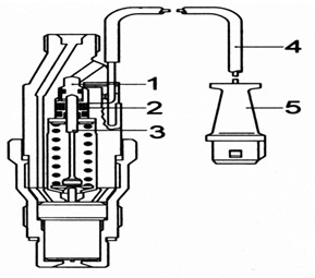 The nozzle has a built-in excitation coil (2) in its body. The ECU supplies a certain reference voltage there. This is done to maintain the current in the electrical circuit constant and regardless of temperature fluctuations.
The nozzle, equipped with a needle lift sensor, consists of:
- adjusting screw (1);
- excitation coils (2);
- rod (3);
- wiring (4);
- electrical connector (4);
This current results in the creation of a magnetic field around the coil. At the moment the nozzle needle is raised, the core (3) changes the magnetic field. This causes a change in voltage and signal. When the needle is in the process of rising, then the pulse reaches its peak and is determined by the ECU, which controls the injection advance angle.
The electronic control unit compares the received impulse with the data in its memory, which corresponds different modes and operating conditions of the diesel unit. The ECU then sends a return signal to the solenoid valve. The said valve is connected to the working chamber of the injection advance machine. The pressure acting on the machine piston begins to change. The result is the movement of the piston under the action of the spring. This changes the injection advance angle.
The maximum pressure that can be achieved using electronic fuel supply control based on the VE fuel pump is 150 kgf/cm2. It is worth noting that this scheme is complex and outdated, the voltages in the cam drive have no further development prospects. The next stage in the development of fuel injection pumps are new generation circuits.
Pump VP-44 and direct injection system for diesel internal combustion engines
This scheme is successfully used on the latest models of diesel cars from the world's leading concerns. These include BMW, Opel, Audi, Ford, etc. Pumps of this type make it possible to obtain an injection pressure of 1000 kgf/cm2.
The direct injection system with a VP-44 fuel pump, shown in the figure, includes:
- A-group of actuators and sensors;
- B-group of devices;
- C-circuit low pressure;
- D- system for providing air supply;
- E- system for removing harmful substances from exhaust gases;
- M-torque;
- CAN-on-board communication bus;
- pedal travel control sensor to control fuel supply;
- clutch release mechanism;
- brake pad contact;
- vehicle speed controller;
- glow plug and starter switch;
- vehicle speed sensor;
- inductive crankshaft speed sensor;
- coolant temperature sensor;
- sensor for measuring the temperature of the air entering the intake;
- boost pressure sensor;
- film-type sensor for measuring intake air mass flow;
- combined instrument panel;
- electronically controlled air conditioning system;
- diagnostic connector for connecting a scanner;
- ON time control unit for glow plugs;
- injection pump drive;
- ECU for engine control and fuel injection pump;
- injection pump;
- filter fuel element;
- fuel tank;
- an injector sensor that controls the needle stroke in the 1st cylinder;
- pin type glow plug;
- power point;
This system has a characteristic feature, which is a combined control unit for the fuel injection pump and other systems. The control unit is structurally composed of two parts, terminal stages and power supply for electromagnets located on the fuel pump housing.
Injection pump device VP-44
- fuel pump;
- pump shaft position and frequency sensor;
- Control block;
- spool;
- supply electromagnet;
- injection advance angle electromagnet;
- hydraulic drive of the actuator to change the injection advance angle;
- rotor;
- cam washer;
- four or six a-cylinders;
- b-for six cylinders;
- c-for four cylinders;
- cam washer;
- video clip;
- drive shaft guide grooves;
- roller shoe;
- injection plunger;
- distributor shaft;
- high pressure chamber;
The system works in such a way that torque from the drive shaft is transmitted through the connecting washer and spline connection. This torque goes to the distributor shaft. The guide grooves (3) perform such a function that, through the shoes (4) and the rollers (2) located in them, the injection plungers (5) are activated so that this corresponds to the internal profile that the cam washer (1) has. The number of cylinders in a diesel internal combustion engine is equal to the number of cams on the washer.
The injection plungers in the distributor shaft housing are located radially. For this reason, such a system is called fuel injection pump. The plungers jointly extrude the incoming fuel on the ascending profile of the cam. Next, the fuel enters the main high-pressure chamber (7). The injection pump may have two, three or more injection plungers, which depends on the planned load on the engine and the number of cylinders (a, b, c).
The process of distributing fuel using a distributor housing
This device is based on:
- flange (6);
- distribution sleeve (3);
- the rear part of the distributor shaft (2) located in the camshaft sleeve;
- locking needle (4) of the high pressure solenoid valve (7);
- accumulating membrane (10), which separates the cavities responsible for pumping and draining;
- high pressure line fittings (16);
- discharge valve (15);
In the figure below we see the distributor housing itself:
- a- fuel filling phase;
- b-fuel injection phase;
This system consists of:
- plunger;
- distributor shaft;
- distribution bushing;
- high pressure solenoid valve locking needle;
- channel for reverse fuel drainage;
- flange;
- high pressure solenoid valve;
- high pressure chamber channel;
- an annular fuel inlet channel;
- an accumulating membrane for separating the pumping and drain cavities;
- cavities behind the membrane;
- low pressure chambers;
- distribution groove;
- exhaust channel;
- discharge valve;
- high pressure line fitting;
During the filling phase, on the downward profile of the cams, the plungers (1), which move radially, move outward and move towards the surface of the cam washer. The locking needle (4) is in a free state at this moment and opens the fuel inlet channel. Fuel passes through the low pressure chamber (12), the annular channel (9) and the needle. Next, the fuel is directed from the fuel priming pump through the channel (8) of the distributor shaft and enters the high pressure chamber. All excess fuel flows back through the return drain channel (5).
Injection is carried out using plungers (1) and a needle (4), which is closed. The plungers begin to move on the ascending profile of the cams towards the axis of the distributor shaft. This increases the pressure in the high-pressure chamber.
The fuel, already under high pressure, rushes through the channel of the high-pressure chamber (8). It passes through the distribution groove (13), which in this phase connects the distributor shaft (2) with the exhaust channel (14), the fitting (16) with the discharge valve (15) and the high pressure line with the nozzle. The last stage is the entry of diesel fuel into the combustion chamber of the power plant.
How does fuel dosing work? High pressure solenoid valve
The solenoid valve (valve for setting the injection start timing) consists of the following elements:
- valve seat;
- valve closing direction;
- valve needle;
- electromagnet armature;
- coil;
- electromagnet;
The specified solenoid valve is responsible for the cyclic supply and dosing of fuel. The specified high pressure valve is built into the high pressure circuit of the injection pump. At the very beginning of injection, voltage is applied to the electromagnet coil (5) according to a signal from the control unit. The anchor (4) moves the needle (3) by pressing the latter against the seat (1).
When the needle is pressed tightly against the seat, then no fuel flows. For this reason, the fuel pressure in the circuit increases rapidly. This allows the corresponding injector to be opened. When the required amount of fuel is in the combustion chamber of the engine, then the voltage on the electromagnet coil (5) disappears. The high pressure solenoid valve opens, which entails a decrease in pressure in the circuit. The decrease in pressure causes the fuel injector to close and injection to stop.
All the accuracy with which this process is carried out directly depends on the solenoid valve. If we try to explain in even more detail, then from the moment the valve ends. This moment is solely determined by the absence or presence of voltage on the solenoid valve coil.
Excess injected fuel, which continues to be injected until the plunger roller passes the top point of the cam profile, moves through a special channel. The end of the path for fuel is the space behind the accumulating membrane. In the low-pressure circuit, surges from high pressure occur, which are damped by the accumulating membrane. An additional feature is that this space stores (accumulates) the accumulated fuel for filling before the next injection.
The engine is stopped using a solenoid valve. The fact is that the valve completely blocks the injection of fuel under high pressure. This solution completely eliminates the need for an additional stop valve, which is used in distribution injection pumps where the control edge is controlled.
The process of damping pressure waves using a discharge valve with throttled return flow
This injection valve (15), which throttles the return flow after completion of the injection of a portion of fuel, prevents the next opening of the injector nozzle. This completely eliminates the phenomenon of additional injection resulting from pressure waves or their derivatives. This additional injection increases the toxicity of exhaust gases and is an extremely undesirable negative phenomenon.
When fuel supply starts, then the valve cone (3) opens the valve. At this very moment, fuel is already pumped through the fitting, penetrates the high pressure line and is directed to the nozzle. The end of fuel injection causes a sharp drop in pressure. For this reason, the return spring forces the valve cone back onto the valve seat. When the injector closes, reverse pressure waves occur. These waves are successfully damped by the discharge valve throttle. All these actions prevent unwanted injection of fuel into the working combustion chamber of a diesel engine.
Injection advance device
This device consists of the following elements:
- cam washer;
- ball pin;
- plunger for setting the injection advance angle;
- underwater and outlet channel;
- adjustment valve;
- vane pump for pumping fuel;
- fuel removal;
- fuel inlet;
- supply from the fuel tank;
- control piston spring;
- return spring;
- control piston;
- annular hydraulic seal chamber;
- throttle;
- solenoid valve (closed) for setting the injection start point;
The optimal combustion process and the best power characteristics of a diesel internal combustion engine are only possible when the moment of combustion of the mixture begins at a certain position of the crankshaft or piston in the diesel engine cylinder.
The injection advance device performs one very important task, which is to increase the angle at which the fuel supply begins at the moment when the crankshaft speed increases. This device structurally includes:
- fuel injection pump drive shaft rotation angle sensor;
- Control block;
- solenoid valve for setting the injection start timing;
The device provides the very optimal moment for the start of injection, which ideally suits the engine operating mode and load on it. There is compensation for the time shift, which is determined by the reduction in the injection and ignition period with increasing rotation speed.
This device is equipped with a hydraulic drive and is built into the lower part of the injection pump housing so that it is located transverse to the longitudinal axis of the pump.
Operation of the injection advance device
The cam washer (1) enters with a ball pin (2) into the transverse hole of the plunger (3) in such a way that the translational movement of the plunger is transformed into rotation of the cam washer. The plunger in the center has a control valve (5). This valve opens and closes the control hole in the plunger. Along the axis of the plunger (3) there is a control piston (12), which is loaded by a spring (10). The piston is responsible for the position of the control valve.
The solenoid valve for setting the injection start timing (15) is located across the axis of the plunger. The electronic unit that controls the fuel injection pump acts on the plunger of the injection advance device through this valve. The control unit continuously supplies current pulses. Such pulses are characterized by a constant frequency and variable duty cycle. The valve changes the pressure that acts on the control piston in the design of the device.
Let's sum it up
This material is aimed at providing users of our resource with the most accessible and understandable introduction to the complex structure of a high-pressure fuel pump and an overview of its main elements. Device and general principle The operation of the injection pump allows us to speak of trouble-free operation only if the diesel unit is refueled with high-quality fuel and engine oil.
As you already understand, low-grade diesel fuel is the main enemy of complex and expensive diesel fuel equipment, the repair of which is often very expensive.
If you operate the diesel engine carefully, strictly observe and even shorten the service intervals for replacing the lubricant, and take into account other important requirements and recommendations, then the injection pump will certainly respond to its caring owner with exceptional reliability, efficiency and enviable durability.
Any car engine has a power system that ensures mixing of the components of the combustible mixture and supplying them to the combustion chambers. The design of the power system depends on what fuel the power plant runs on. But the most common is a gasoline-powered unit.
In order for the power system to mix the components of the mixture, it must also receive them from the container in which the gasoline is located - the fuel tank. And for this purpose, the design includes a pump that supplies gasoline. And it seems that this component is not the most important, but without its work the engine simply will not start, since gasoline will not flow into the cylinders.
Types of fuel pumps and their operating principles
Cars use two types of gasoline pumps, which differ not only in design, but also in installation location, although they have the same task - to pump gasoline into the system and ensure its supply to the cylinders.
By type of design, gasoline pumps are divided into:
- Mechanical;
- Electrical.
1. Mechanical type

A mechanical type fuel pump is used on. It is usually located on the head of the power unit, since it is driven by the camshaft. Fuel is pumped into it due to the vacuum created by the membrane.

Its design is quite simple - the body contains a membrane (diaphragm), which is spring-loaded at the bottom and attached in the central part to a rod connected to the drive lever. At the top of the pump there are two valves - inlet and outlet, as well as two fittings, one of which draws gasoline into the pump, and from the second it comes out and enters the carburetor. Working area the mechanical type has a cavity above the membrane.
The fuel pump works according to this principle - there is a special eccentric cam on the camshaft, which drives the pump. While the engine is running, the shaft, rotating, acts with the top of the cam on the pusher, which presses the drive lever. This, in turn, pulls the rod down along with the membrane, overcoming the force of the spring. Because of this, a vacuum is created in the space above the membrane, due to which the intake valve comes off and gasoline is pumped into the cavity.
Video: How a fuel pump works
As soon as the shaft rotates, the spring returns the pusher, drive lever and diaphragm along with the rod into place. Because of this, pressure increases in the cavity above the membrane, due to which the inlet valve closes and the outlet valve opens. The same pressure pushes gasoline out of the cavity into the outlet fitting and it flows into the carburetor.
That is, the entire work of a mechanical pumpless type is based on pressure drops. But we note that the entire carburetor power system does not require high pressure, therefore the pressure created by the mechanical fuel pump is small, the main thing is that this unit provides required amount gasoline in the carburetor.
Such a fuel pump works constantly while the engine is functioning. When the power unit stops, the supply of gasoline stops because the pump also stops pumping. To ensure that there is enough fuel to start the engine and keep it functioning until the system is filled due to vacuum, the carburetor has chambers into which gasoline is poured even before the engine is running.
2. Electric fuel pump, their types

In fuel injection systems, gasoline is injected by injectors, and for this it is necessary that the fuel reaches them under pressure. Therefore, using a mechanical type pump is not possible here.
An electric fuel pump is used to supply gasoline to the fuel injection system. Such a pump is located in the fuel line or directly in the tank, which ensures that gasoline is pumped under pressure into all components of the power system.
Let us briefly mention the most modern injection system - with direct injection. It works on the principle of a diesel system, that is, gasoline is injected directly into the cylinders under high pressure, which a conventional electric pump cannot provide. Therefore, such a system uses two nodes:
- The first of them is electric, installed in the tank, and it ensures that the system is filled with fuel.
- The second pump, a high-pressure pump (HPF), has a mechanical drive and its task is to provide significant fuel pressure before supplying it to the injectors.
But we won’t look at fuel injection pumps for now, but will look at conventional electric fuel pumps, which are located either near the tank and embedded in the fuel line, or installed directly into the container.
Video: Gasoline pump, checking and testing
There are a large number of species, but three types are most widespread:
- rotary-roller;
- gear;
- centrifugal (turbine);
The rotary roller electric pump refers to pumps that are installed in the fuel line. Its design includes an electric motor, on the rotor of which a disk with rollers is installed. All this is placed in the supercharger cage. Moreover, the rotor is slightly offset in relation to the supercharger, that is, there is an eccentric arrangement. The supercharger also has two outlets - gasoline enters the pump through one, and out through the second.
It works like this: when the rotor rotates, the rollers pass through the inlet zone, which creates a vacuum and gasoline is pumped into the pump. Its rollers are captured and transferred to the exhaust zone, but first, due to the eccentric location, the fuel is compressed, which is how pressure is achieved.

Due to the eccentric movement, a gear-type pump also operates, which is also installed in the fuel line. But instead of a rotor and a supercharger, its design contains two internal gears, that is, one of them is placed inside the second. In this case, the internal gear is the driving one, it is connected to the electric motor shaft and is shifted relative to the second one – the driven one. During operation of such a pump, fuel is pumped through the teeth of gears.

But on cars, a centrifugal electric fuel pump is most often used, which is installed directly into the tank, and a fuel line is already connected to it. Its fuel supply is carried out by an impeller, which has a large number of blades and is placed inside a special chamber. During the rotation of this impeller, turbulence is created that promotes the suction of gasoline and its compression, which provides pressure before being supplied to the fuel line.
These are simplified diagrams of the most common electric fuel pumps. In reality, their design includes valves, contact systems for connecting to the on-board network, etc.
Note that already during the startup of the injection power plant, the system must already contain fuel under pressure. Therefore, the electric fuel pump is controlled by an electronic control unit, and it starts working before the starter is activated.
Basic fuel pump malfunctions
Video: When the fuel pump is sick
All gasoline pumps have a fairly long service life due to their relatively simple design.
Problems are very rare in mechanical components. They most often occur due to rupture of the membrane or wear of the drive elements. In the first case, the pump stops pumping fuel altogether, and in the second, it supplies it in insufficient quantities.
Checking such a fuel pump is not difficult; just remove the top cover and assess the condition of the membrane. You can also disconnect the fuel line coming from the carburetor, lower it into a container and start the engine. For a serviceable element, fuel is supplied in uniform portions with a fairly powerful jet.
In injection engines, a malfunction of the electric fuel pump has certain symptoms - the car does not start well, there is a noticeable drop in power, and interruptions in engine operation are possible.
Of course, such signs may indicate malfunctions in different systems, therefore, additional diagnostics will be required in which the performance of the pump is checked by measuring pressure.
But the list of faults due to which this unit does not work correctly is not so many. Thus, the pump may stop working due to severe and systematic overheating. This happens due to the habit of pouring small portions of gasoline into the tank, because the fuel acts as a coolant for this unit.
Refueling with low-quality fuel can easily lead to malfunctions. The impurities and foreign particles present in such gasoline, getting inside the unit, lead to increased wear of it components.
Problems can also arise through the electrical part. Wiring oxidation and damage can result in insufficient power being supplied to the pump.
Note that most malfunctions that occur due to damage or wear of the components of the fuel pump are difficult to eliminate, so often if its performance is impaired, it is simply replaced.
Used on a variety of types of transport and equipment, it is based on the combustion of the fuel-air mixture and the energy released as a result of this process. But in order for the power plant to function, fuel must be supplied in portions at strictly defined moments. And this task lies with the power system included in the design of the motor.
Engine fuel supply systems consist of a number of components, each of which has its own task. Some of them filter the fuel, removing contaminants from it, others dosage and supply it to the intake manifold or directly to the cylinder. All these elements perform their function with fuel, which still needs to be supplied to them. And this is ensured by the fuel pumps used in system designs.
Pump assembly
Like any liquid pump, the task of the unit used in the engine design is to pump fuel into the system. Moreover, almost everywhere it is necessary that it be supplied under a certain pressure.
Types of fuel pumps
Different types of engines use their own types of fuel pumps. But in general, they can all be divided into two categories - low and high pressure. The use of a particular unit depends on the design features and operating principle of the power plant.
So, for gasoline engines, since the flammability of gasoline is much higher than diesel fuel, and at the same time the fuel-air mixture ignites from an external source, high pressure in the system is not required. Therefore, low pressure pumps are used in the design.

Gasoline engine pump
But it is worth noting that in the latest generation gasoline injection systems, fuel is supplied directly to the cylinder (), so gasoline must be supplied under high pressure.
As for diesel engines, the mixture ignites due to the influence of pressure in the cylinder and temperature. In addition, the fuel itself is directly injected into the combustion chambers, so for the nozzle to inject it, significant pressure is required. And for this purpose, the design uses a high-pressure pump (HHP). But we note that the design of the power system could not have done without the use of a low-pressure pump, since the injection pump itself cannot pump fuel, because its task is only to compress and supply it to the injectors.
All pumps used in power plants different types can also be divided into mechanical and electrical. In the first case, the unit operates from a power plant (a gear drive is used or from shaft cams). As for electric ones, they are driven by their own electric motor.
More specifically, on gasoline engines, power systems use only low-pressure pumps. And only the injector with direct injection has a fuel injection pump. Moreover, in carburetor models this unit had a mechanical drive, but in injection models electrical elements are used.

Mechanical fuel pump
In diesel engines, two types of pumps are used - low pressure, which pumps fuel, and high pressure, which compresses diesel fuel before it enters the injectors.
The diesel fuel priming pump is usually mechanically driven, although there are also electric models. As for the fuel injection pump, it is driven by the power plant.
The difference in pressure generated by low and high pressure pumps is very striking. So, for the injection power system to operate, only 2.0-2.5 Bar is enough. But this is the operating pressure range of the injector itself. The fuel pumping unit, as usual, provides it a little in excess. Thus, the pressure of the injector fuel pump varies from 3.0 to 7.0 Bar (depending on the type and condition of the element). As for carburetor systems, gasoline is supplied with virtually no pressure.
But diesel engines require very high pressure to supply fuel. If we take the latest generation Common Rail system, then in the fuel injection pump-injector circuit the diesel fuel pressure can reach 2200 Bar. Therefore, the pump operates from a power plant, since its operation requires quite a lot of energy, and it is not advisable to install a powerful electric motor.
Naturally, the operating parameters and the pressure created affect the design of these units.
Types of fuel pumps, their features
We will not disassemble the structure of the fuel pump of a carburetor engine, since such a power system is no longer used, and it is structurally very simple, and there is nothing special about it. But the electric injector fuel pump should be considered in more detail.
It is worth noting that different cars use different types of fuel pumps that differ in design. But in any case, the unit is divided into two components - mechanical, which ensures fuel injection, and electrical, which drives the first part.
The following pumps can be used on injection vehicles:
- Vacuum;
- Roller;
- Gear;
- Centrifugal;

Rotary pumps
And the difference between them mainly comes down to the mechanical part. And only the design of the vacuum-type fuel pump is completely different.
Vacuum
The operation of the vacuum pump is based on a conventional fuel pump of a carburetor engine. The only difference is in the drive, but the mechanical part itself is almost identical.
There is a membrane dividing the working module into two chambers. In one of these chambers there are two valves - inlet (connected by a channel to the tank) and outlet (leading to the fuel line, which supplies fuel further into the system).
This membrane, when moving forward, creates a vacuum in the chamber with valves, which leads to the opening of the inlet element and the pumping of gasoline into it. During reverse movement, the intake valve closes, but the exhaust valve opens and the fuel is simply pushed into the line. In general, everything is simple.
As for the electrical part, it works on the principle of a pull-in relay. That is, there is a core and a winding. When voltage is applied to the winding, the magnetic field that arises in it draws in the core connected to the membrane (its translational movement occurs). As soon as the voltage disappears, the return spring returns the membrane to its original position (return movement). The supply of impulses to the electrical part is controlled by the electronic injector control unit.
Roller
As for the other types, their electrical part is, in principle, identical and is a conventional DC electric motor operating from a 12 V network. But the mechanical parts are different.

Roller fuel pump
In the roller type of pump, the working elements are a rotor with grooves made in which the rollers are installed. This design is housed in a housing with an internal cavity complex shape, having chambers (inlet and outlet, made in the form of grooves and connected to the supply and outlet lines). The essence of the work comes down to the fact that the rollers simply transfer gasoline from one chamber to the second.
Gear
The gear type uses two gears mounted one inside the other. The inner gear is smaller in size and moves along the eccentric path. Thanks to this, there is a chamber between the gears, in which fuel is captured from the supply channel and pumped into the exhaust channel.

Gear pump
Centrifugal type
Roller and gear types of electric fuel pumps are less common than centrifugal ones, they are also turbine ones.

Centrifugal pump
This type of fuel pump design includes an impeller with a large number of blades. When rotating, this turbine creates turbulence in gasoline, which ensures that it is sucked into the pump and further pushed into the main line.
We looked at the design of fuel pumps a little simplified. Indeed, in their design there are additional inlet and pressure reducing valves, whose task is to supply fuel in only one direction. That is, gasoline that gets into the pump can only return to the tank through the return line, having passed through all constituent elements power systems. Also, the task of one of the valves is to shut off and stop injection under certain conditions.

Turbine pump
As for high-pressure pumps used in diesel engines, the principle of operation is radically different, and you can learn more about such components of the power system here.