Fire-fighting water supply is a set of measures to provide water to various consumers to extinguish a fire. The problem of fire-fighting water supply is one of the main ones in the field of firefighting. Modern systems water supply systems are complex engineering structures and devices that ensure reliable water supply to consumers. With the development of water supply to populated areas and industrial enterprises, their fire protection is improving, since the design, construction, and reconstruction of water pipelines take into account not only economic and industrial needs, but also fire safety needs. Basic fire safety requirements provide for the need to supply standard volumes of water under a certain pressure during the estimated fire extinguishing time.
Types of water pipelines. Classification of water supply systems by pressure.
According to their purpose, water supply systems are divided into utility and drinking water supply, industrial and fire safety. Depending on the pressure, fire-fighting water pipelines of high and low pressure. In fire-fighting water supply high pressure within 5 minutes after reporting a fire, they create the pressure necessary to extinguish a fire in the tallest building without the use of fire engines. For this purpose, stationary fire pumps are installed in pumping station buildings or in other separate rooms.
In low-pressure water supply systems during a fire, fire pumps are used to create the required pressure, which are connected to fire hydrants using suction hoses.
In high-pressure water supply systems, water is supplied to the fire site through hose lines directly from hydrants under pressure from stationary fire pumps installed in the pumping station.
All water supply structures are designed so that during operation they pass the calculated water flow for fire needs with the maximum water flow for household, drinking and industrial needs. In addition, in tanks clean water and water towers provide an untouchable supply of water for extinguishing fires, and fire pumps are installed in the second lift pumping stations.
Pump-hose systems, which are assembled when extinguishing fires, are also elementary high-pressure fire-fighting water supply systems, consisting of a water supply source, a water intake (suction grid), a suction line, a combined pumping station of the first and second lift (fire pump) , water pipelines (main hose lines), water supply network (working hose lines).
Water towers are designed to regulate pressure and flow in the water supply network. They are installed at the beginning, middle and end of the water supply network. A water tower consists of a support (trunk), a tank and a tent-device that protects the tank from cooling and freezing the water in it. The height of the tower is determined by hydraulic calculation taking into account the terrain. Typically the tower height is 15...40 m.
The capacity of the tank depends on the size of the water supply system, its purpose and can vary widely: from several cubic meters on low-power water supply lines to tens of thousands of cubic meters on large urban and industrial water supply lines. The size of the control tank is determined depending on the water consumption schedules and the operation of pumping stations. In addition, an emergency fire reserve is included to extinguish one external and one internal fire within 10 minutes. The tank is equipped with discharge, collapsible, overflow and mud pipes. Often the discharge and discharge pipes are combined.
A type of water towers are water tanks, which are designed not only to regulate pressure and flow in the water supply network, but also to store a fire-fighting supply of water for extinguishing fires for 3 hours. Reservoirs are located in elevated places.
Water tanks and towers are connected to the water supply network in series and in parallel. When switched on in series, all the water from the pumping stations passes through them. In this case, the discharge and collapsible pipes are not combined, and they work separately. At minimum water consumption, excess water is accumulated in a reservoir or tank, and at maximum, this supply is sent to the water supply network.
When connected in parallel to the water supply network, excess water is supplied to reservoirs and tanks (at minimum water consumption), and at maximum water consumption it is sent to the network. In this case, the injection and distribution pipelines can be combined. Measuring devices are provided to monitor the water level in tanks and reservoirs.
Based on the type of facility being serviced, water supply systems are divided into urban, settlement, as well as industrial, agricultural, railway, etc.
Based on the type of natural sources used, a distinction is made between water pipelines that take water from surface sources (rivers, reservoirs, lakes, seas) and underground (artesian, spring). There are also mixed supply water pipes.
According to the method of supplying water, there are pressure pipelines with mechanical water supply by pumps and gravity (gravity) ones, which are installed in mountainous areas when the water source is located at an altitude that ensures a natural supply of water to consumers.
According to their purpose, water supply systems are divided into household and drinking water systems that satisfy the needs of the population; production technological processes supplying water; fire and combined. The latter are usually held in populated areas. From these same water pipelines, water is also supplied to industrial enterprises if they consume a small amount of water or the conditions of the production process require drinking-quality water.
With high water consumption, enterprises may have independent systems water supply, providing for their drinking, industrial and fire-fighting needs. In this case, fire-fighting and industrial water pipelines are usually constructed. The combination of fire water supply with household water supply, and not with industrial water supply, is explained by the fact that the industrial water supply network is usually less extensive and does not cover all volumes of the enterprise. Moreover, for some technological processes production, water must be supplied under a strictly defined pressure, which will change when extinguishing a fire. And this can lead either to an increase in water consumption, which is not economically feasible, or to a breakdown of production equipment. An independent fire-prevention water supply system is usually installed at the most fire-hazardous facilities—enterprises of the petrochemical and oil refining industries, oil and petroleum product warehouses, lumber yards, liquefied gas storage facilities, etc.
Water supply systems can serve one object, for example a city or an industrial enterprise, or several objects. In the latter case, these systems are called group systems. If a water supply system serves one building or a small group of closely spaced buildings from a nearby source, it is called a local system. To supply water under the required pressure to different areas of the territory of a populated area, which have a significant difference in elevations, zone water supply is arranged. A water supply system that serves several large water consumers located in a certain area is called a district one.
On the territory of most populated areas (cities, towns) there are various categories water consumers who have various requirements for the quality and quantity of water consumed. In modern city water supply systems, water consumption for technological needs of industry averages about 40% of the total volume supplied to the water supply network. Moreover, about 84% of water is taken from surface sources and 16% from underground
The water supply or design system is usually divided into two parts: external and internal. External water supply includes all structures for the intake, purification and distribution of water through a water supply network up to the entrances to buildings. Internal water pipelines are a set of devices that ensure the receipt of water from the external network and its supply to water distribution devices located in the building.
The supply of water for firefighting purposes in cities is provided by fire trucks from hydrants installed on the water supply network. In small cities, additional pumps are turned on in the PS-I to supply water for extinguishing fires, and in large cities, fire flow constitutes an insignificant part of water consumption, therefore they have practically no effect on the operating mode of the water supply system.
In accordance with modern standards, in settlements with a population of up to 500 people, which are located mainly in rural areas, an integrated high-pressure water supply system must be installed to provide household, drinking, industrial and fire-fighting needs. However, there are often cases when only a drinking water supply system is built, and for firefighting needs water is supplied by mobile pumps from reservoirs and reservoirs replenished from the water supply system.
In small settlements, for economic and fire-fighting needs, local water supply systems are most often installed with water taken from underground sources (mine wells or boreholes). Centrifugal and piston pumps, Airlift systems, wind power plants, etc. are used as water-lifting devices. They are the most reliable and easy to use. centrifugal pumps. As for other water-lifting devices, due to their low productivity they can only be used to replenish fire water supplies in reservoirs, reservoirs, and water towers.
Water supply sources
According to two categories natural sources Water intake structures are also divided into two groups: structures for receiving water from surface sources and structures for receiving groundwater. The choice of a particular source of water supply is determined by local natural conditions, sanitary and hygienic requirements for water quality, and technical and economic considerations. If possible, preference should be given to underground water supply sources.
Surface sources include rivers, lakes and, in some cases, seas. The location of the water intake is determined in such a way that the following conditions are satisfied:
the possibility of using the simplest and cheapest method of collecting water from a source;
uninterrupted receipt of the required amount of water;
ensuring the supply of the purest possible water (purification from pollution);
the closest location to the facility supplied with water (to reduce the cost of water supply and water supply).
Groundwater occurs at different depths and in different rocks.
For water supply use:
water from pressure aquifers covered on top by waterproof rocks that protect groundwater from pollution;
non-pressure groundwater with a free surface, contained in layers that do not have a water-permeable roof;
spring (spring) waters, i.e. underground waters that independently come to the surface of the earth;
mine and mine waters (usually for industrial water supply), i.e. groundwater entering drainage structures during the extraction of minerals.
Construction of a fire hydrant and requirements for operation in winter and summer time
A hydrant with a fire column is a water intake device installed on a water supply network and designed to draw water when extinguishing a fire.
When extinguishing a fire, a hydrant with a column can be used, firstly, as an external fire hydrant in the case of connecting a fire hose to supply water to the fire extinguishing site and, secondly, as a water supply for a fire truck pump.
Depending on the design features and conditions fire protection In protected areas, hydrants are divided into underground and above-ground.
Underground hydrants are installed in special wells covered with a lid. The fire hose is screwed onto the underground hydrant only when it is in use. An above-ground hydrant is located above the surface of the ground with a column attached to it.
A fire hydrant is designed to draw water from the water supply network to extinguish fires; it consists of a riser, a valve, a valve box, a rod, a threaded installation head and a cover. If the groundwater level is high, install a check valve.
Conditional bore, mm................................................... .................................... 125
Rotational speed of the rod until the valve is fully opened, revolutions......
Force when opening a hydrant, N (kg)................................................. ..............
A hydrant column is installed on a water supply network using a fire stand without installing a well. The throughput capacity of the combined hydrant is 20 l/s.
The fire stand is used for opening and closing a fire hydrant, as well as connecting fire hoses when drawing water from the water supply network to extinguish fires. The main parts of the speaker are the body and the head. At the bottom of the housing there is a threaded ring for connecting the column to a fire hydrant. In the upper part there are column controls and two pipes with connecting heads and two valves. A central key (tubular rod) with a square coupling at the bottom and a handle at the top passes through the gland in the head of the column. The handle is rotated with the valves of the pressure pipes closed. When the valves are open, the handwheels will fall into the field of rotation of the handle. Thus, the column has a lock that prevents the central key from turning when the valves of the pressure pipes are open. Remove the column from the hydrant only when the hydrant valve is closed.
Technical characteristics of underground fire hydrant
Conditional bore, mm................................................... ......................................
Working pressure, MPa (kgf/cm2) .............................................. ........................
Conditional bore of the connecting head, mm....................................................
Weight, kg, no more................................................... ...........................................
Requirements for the operation of fire hydrants in winter and summer
There are mandatory rules for the operation of fire hydrants. Failure to properly handle fire hydrants can lead to breakdowns in the water supply network, interruption of water supply, and accidents.
Preparation of fire-fighting water supply for operation in winter conditions is carried out:
urban water supply - during the autumn inspection by mobile teams of AVR REWS (departments);
object water supply - during the autumn inspection by the water supply services of the objects.
Preparation of fire-fighting water supply for operation in winter conditions includes:
pumping water from the risers of Moscow-type fire hydrants and sealing drain holes with wooden plugs;
at steady state sub-zero temperature outside air, pumping water from hydrant wells filled above the riser level, followed by performing step 1;
fire hydrants subject to flooding by groundwater and melt water are taken into special accounting (Appendix No. 1 “Instructions...”) by linear sections of REWS and district fire departments with a mandatory mark in the book of fire-fighting water supply inspections, subsequent monitoring of their condition by REWS, pumping water from risers after thaws (if necessary) and mandatory transfer of information to regional fire departments;
filling hydrant wells with special heat-insulating filler.
Requirements for the commissioning of new sources of fire-fighting water supply.
To the fire hydrants
Fire hydrants should be installed on ring water supply networks. It is allowed to install fire hydrants on dead-end lines, regardless of the water consumption for fire extinguishing, provided that their length does not exceed 200 meters.
The diameter of the water supply pipes on which fire hydrants are installed is determined by calculation in accordance with clause 8.46 of SNiP 2.04.02-84 "Water supply. External networks and structures", but the minimum diameter of water supply pipes in populated areas and industrial enterprises must be no less 100 mm, in rural areas - at least 75 mm, the maximum diameter of pipes should not exceed 500 mm.
Fire hydrants should be located along highways at a distance of no more than 2.5 m from the edge of the roadway, but no closer than 5 m from the walls of buildings. It is allowed to place hydrants on the roadway. In the historical part of the city, it is allowed to place fire hydrants in accordance with the requirements of clause 8.55 of VSN-89. The distance between hydrants should not exceed 150 meters.
Around the hatches of wells located in built-up areas, off-road pavements or in a green zone, blind areas 1 m wide should be provided with a slope from the hatches; the blind areas should be 0.05 m higher than the adjacent territory; on the roadway of streets with improved permanent surfaces, manhole covers must be flush with the surface of the roadway; well hatches on water pipelines laid in undeveloped areas should be 0.2 m above the ground surface.
There must be a free access to the hydrant with a width of at least 3.5 meters.
At the location of the fire hydrant, an indication sign must be installed at a height of 2-2.5 m from the ground surface (signs at facilities made in accordance with GOST 12.4.026-76 “Signal colors and safety signs” are installed directly at water sources and in the direction of movement towards him). The plate must be 12x16 cm in size, red and have inscriptions white indicating:
hydrant type (Moscow type hydrant is designated by the letter M);
diameter of the water supply network in millimeters (inches);
the nature of the water supply network (a dead-end network is indicated by the letter T in the upper left corner of the sign);
fire hydrant number (must match the number of the house on which the coordination plate is located). Recording numbers with a "0" in front (02/01/03, etc.) means that these fire hydrant signs are located on trees, metal posts or poles street lighting, without reference to house numbers;
digital value of the distance in meters from the sign to the hydrant.
In accordance with clause 1.12. GOST 12.4.009-83 fire hydrant signs must be illuminated with lamps or made using fluorescent or reflective coatings
Hydrants in wells are installed vertically. The axis of the installed hydrant should be located no closer than 175 mm and no further than 200 mm horizontally from the wall of the manhole neck. The distance from the top of the hydrant to the top edge of the hatch should be no more than 400 mm and no less than 150 mm. The technical condition of the fire hydrant is checked by installing a column with the obligatory release of water, and there should be no leakage of water in the flange connections of the hydrant.
After fire hydrants are put into operation, an act is drawn up in 4 copies (one copy each for the fire department, DSPT, REVS (department) and the organization that carried out the construction and installation work).
When accepting hydrants located on on-site water supply networks into operation, it is necessary to additionally test the network for water loss. After fire hydrants are put into operation at the site, a free-form act is drawn up in 4 copies (one for the district fire department, the second for the customer, the third for the general contractor, the fourth for DSPT). Based on the act, the characteristics of the fire water supply of the facility are included in the summary statement of the facility water supply.
To gravity wells
To extract water from natural water sources with swampy banks or the impossibility of direct water intake from them for fire extinguishing purposes, gravity (receiving) wells are installed.
Gravity wells must have plan dimensions of at least 0.8 x 0.8 m. They can be made of concrete, stone and wood. The well must be equipped with two covers, the space between which is winter period filled with insulating material, which protects the water from freezing.
The depth of water in the well must be at least 1.5 m. The well is connected to the water source by a supply pipe, the diameter of which must be at least 200 mm. The end of the pipe extending into the water source must be located at least 0.5 m above the bottom and at least 1.0 m below the low water horizon. A metal wire mesh must be attached to the end of the pipe on the water source side to prevent suction into the water source. pipe of fish and various items.
There must be free access to the gravity well, designed for the simultaneous installation of two fire trucks. A light or fluorescent sign with the inscription “SKN” must be installed at the location of the gravity well.
To fire ponds
The need to install and the required volume of fire-fighting reservoirs for objects and settlements specified in note 1 of clause 2.11. should be determined by water consumption standards for the estimated fire extinguishing time in accordance with the instructions of paragraphs 2.13.-2.17. and 2.24. SNiP 2.04.02-84.
The number of fire reservoirs must be at least two, and in each reservoir half the volume of water for fire extinguishing must be stored (clause 9.29. SNiP 2.04.02-84).
Fire reservoirs should be placed based on the condition that they serve buildings located within the radius of:
If there are car pumps - 200 m;
If there are motor pumps - 100-150 m, depending on the type of motor pumps (clause 9.30. SNiP 2.04.02-84).
Distance from reservoirs to buildings of 3,4 and 5 degrees of fire resistance and up to open warehouses combustible materials must be at least 30 m, to buildings of 1 and 2 degrees of fire resistance - at least 10 m (clause 9.30. SNiP 2.04.02-84).
If the direct intake of water from a fire reservoir using motor pumps or motor pumps is difficult, receiving wells with a volume of 3-5 cubic meters should be provided. meters. The diameter of the connecting pipeline should be taken from the condition of passing the calculated water flow for external fire extinguishing, but not less than 200 mm. In front of the receiving well, a well with a valve should be installed on the connecting pipeline, the steering wheel of which should be located under the manhole cover. A grill should be provided on the connecting pipeline on the reservoir side.
Water must be drawn from each reservoir by at least two fire pumps, preferably from different sides.
Driveways with turning areas for fire trucks, no less than 12x12 m in size, are arranged to fire reservoirs and suction wells.
At the location of the fire reservoir, a light or fluorescent sign must be installed with the following written on it: the letter index PV, digital values of the water reserve per cubic meter. meters and the number of fire trucks that can be simultaneously installed on the site near the reservoir.
To ensure reliable water intake from natural reservoirs with high bank slopes, as well as significant seasonal fluctuations in water horizons, access points (piers) are built that can withstand the load of fire trucks. The access area (pier) should be located no higher than 5 m from the low water horizon (LWH) and no less than 0.7 m above the high water horizon (HWH) and be equipped with a drainage tray for suction hoses. The depth of water, taking into account freezing in winter, must be at least 1 m, otherwise, a pit (pit) is built at the intake site. The width of the platform flooring must be at least 4.5-5 m with a slope towards the shore and have a strong side fence 0.7-0.8 m high. At a distance of 1.5 m from the longitudinal edge of the platform, a thrust beam with a cross-section of less than 25x25 cm.
Chiefs (deputy chiefs) of units must go to technical acceptance of new or reconstructed sources of fire-fighting water supply.
Note: Acceptance of fire hydrants after completion of work on the construction of new and reconstruction of existing fire water supply networks is carried out by SPT TsUS UGPS (2nd shift), or in agreement with it.
Fire water supply inspections
Fire water supply inspections are carried out:
On city water supply networks twice a year (spring - from April 1 to June 1; autumn - from July 15 to November 1) by the forces of mobile teams of emergency restoration work (AVR) of water supply network operating areas (REVS) and branches of the State Enterprise "Vodokanal S" .-Petersburg" with the obligatory presence of a representative of the HR. To carry out an inspection by the linear section of the REWS (department) of the State Enterprise "Vodokanal of St. Petersburg", a "Schedule for the inspection of fire hydrants for the REWS (department)" is drawn up (Appendix No. 14 "Instructions..."), which is approved by the head of the REWS (department) and agreed upon head (deputy head) of the HR. During the spring inspection, only Leningrad type fire hydrants are checked; during the autumn inspection, all fire hydrants are checked.
Object fire-fighting water supply twice a year (spring - from April 1 to June 1; autumn - from August 15 to November 1) by the duty guards of fire departments with the mandatory presence of a representative of the facility's water supply service. The departments, led by the chief of guard, go to check the facility’s water supply from 9:30 a.m. to 11:00 a.m. and after 5:00 p.m., in agreement with the senior engineer of the Department of State Border Guard Service.
When conducting fire-fighting water supply inspections (city and facility), the following is checked:
presence of signs of fire hydrants, reservoirs, gravity wells, piers, entrances and correspondence of coordinates using a tape measure;
presence and condition of entrances to water sources;
presence and condition of the outer cover of hydrants and gravity wells. In winter, the lid must be cleared of ice; loose snow of no more than 10 cm is allowed on it. Responsibility for removing ice and snow from the lids of fire hydrants and gravity wells rests with the heads of REWS (departments) of the State Enterprise "Vodokanal of St. Petersburg" and economic objects (organizations, institutions);
internal state fire hydrant well, gravity well;
availability of water and pressure by installing a column on all hydrants with the obligatory release of water. During the spring inspection of Leningrad-type city hydrants, mud-filled wells are cleaned (if necessary), and during the autumn inspection of all city and facility hydrants;
measures are being taken to prepare them for operation in winter;
depth of the reservoir in the place intended for lowering the fence mesh. In winter, when conducting fire-tactical exercises and exercises, pay attention to the presence and size of the ice hole, clearing the site for the installation of fire trucks;
condition load-bearing structures and flooring, the presence of side rails, a thrust beam and a drainage tray at the fire pier;
checking gravity wells and reservoirs by installing motor pumps with water intake and release.
Note: during inspections, it is not allowed to use socket wrenches, poles and pieces of pipe to open hydrants and start water without installing dispensers (with the exception of German-style hydrants).
Fire water supply checks on city networks.
During the period of fire-fighting water supply inspections on city networks, the mobile brigade of the AVR REVS (department) of the State Enterprise "Vodokanal of St. Petersburg" arrives in its transport according to the schedule at the fire center, from where it proceeds to the inspection site with a representative of the fire department (senior firefighter). The results of the inspection are recorded by the senior firefighter in the fire water supply inspection book. If the water source is in good working order, then the date of inspection and signature is entered in the corresponding column; if the water source is not working properly, the nature of the malfunction is indicated according to the classification of defects (Appendix No. 8 “Instructions...”). The chiefs of guards on their duty days are personally responsible for ensuring that a representative of the fire department (senior firefighter) as part of the mobile brigade of the AVR REVS (department) of the State Enterprise "Vodokanal St. Petersburg" leaves to check the water supply according to the schedule.
Based on the results of the autumn and spring inspection of fire hydrants on the city network, an act is drawn up (Appendix No. 15 “Instructions ...”), which is approved by the head of the REVS (department) of the State Enterprise "Vodokanal St. Petersburg" and agreed upon by the head (deputy head) of the fire department. The act is drawn up in three copies: one - in the REVS (branch); the second - in the frequency converter; the third - in DSPT UGPS.
Information about the malfunction of hydrants on city networks in the area of departure of the control unit after the end of the inspection is transferred to the deputy head of the hazardous production facility for service (senior engineer) for drawing up a GPN Order addressed to the head of the corresponding REVS (department) of the State Enterprise "Vodokanal of St. Petersburg". Malfunctions of water sources discovered while extinguishing fires are recorded in the inspection book and a telephone message is sent to the REVS (department) of the State Enterprise "Vodokanal of St. Petersburg" indicating the time frame for elimination. In case of non-compliance with the State Fire Regulations and telephone messages to deadlines those responsible for fire-fighting water supply in hazardous production facilities are obliged to apply to the heads of REWS (branches) of the State Enterprise "Vodokanal of St. Petersburg" the rights provided for by the "Regulations on State Fire Supervision".
The REVS (department) of the State Enterprise "Vodokanal of St. Petersburg" informs the PC in the form of a telephone message indicating the timing of their re-inspection about the elimination of malfunctions of fire hydrants. For a re-inspection, the mobile brigade of the AVR REVS (department) of the State Enterprise "Vodokanal of St. Petersburg" goes with a representative of the fire department (senior firefighter), who records the results of eliminating defects with an indication of the date in the book of fire-fighting water supply inspections and reports on them to the deputy head of the fire department.
Inspections of on-site fire water supply.
For high-quality study and control over the state of the fire-fighting water supply, economic objects (organizations, institutions) are assigned to guard chiefs by order for a period of half a year. Guard commanders are personally responsible for timely control condition of fire-fighting water supply sources at the facilities assigned to them within the established time frame.
All defects in fire-fighting water supply sources identified at economic facilities during the inspection period are entered into the Inspection Book. If faults in water sources are discovered during an inspection, the chief of guard draws up an administrative protocol against the perpetrators responsible persons, which is transferred for analysis and issuance of a decision to the State Fire Inspectorate inspector assigned to the facility. A consolidated list of water sources that have not been repaired for 3 or more months should be sent in the form " alarm signal"(Appendix No. 3 "Instructions...") in the DSPT of the UGPS
Information about malfunctions of water sources at facilities served by the State Fire Inspectorate of other ministries and departments should be sent, signed by the head of the hazardous production facility, to departmental inspections.
The inspection staff of Gospozhnadzor bears personal responsibility for monitoring the progress of troubleshooting fire water supply sources at assigned facilities.
Information from economic entities (organizations, institutions) about the implementation of work to eliminate defects in water sources must be checked on site; if the water source is in good condition, a corresponding entry is made in the inspection book and a date is set.
All information about the state of city and facility sources of fire-fighting water supply, obtained during the period of inspections, during fire extinguishing, fire-tactical exercises and classes (PTU, PTZ), is entered into the Water Supply Inspection Book by the senior firefighter on duty during the inspection of the water source, or immediately after returning to the unit from the fire, vocational school (PTZ). When troubleshooting a water source, an entry in the Inspection Book is made after a repeat (control) check of its condition by the senior fireman on duty. The book of fire-fighting water supply checks is filled out monthly by the deputy head of the fire department immediately before drawing up an operational report on the state of the fire-fighting water supply in the protected area. If the condition of the water source has not changed for the current month, then the information from the previous month is entered into the corresponding column of the Inspection Book and a signature is placed.
Based on the entries in the inspection book, the person responsible for fire water supply in the PCH monthly, before the 25th day, makes:
information about the malfunction of the fire-fighting water supply in the area where the PCH departs (Appendix No. 5 “Instructions...”), which are transported one copy at a time on the main vehicles;
an operational report on the state of fire-fighting water supply in the protected area (Appendix No. 2 “Instructions...”), which is transmitted to the Duty Department of the Central Control Center of the UGPS on the 26-27-28-29 of each month on the day of duty of the second guard.
Methodology for testing water supply for water loss
Water supply networks are tested during hours of maximum water consumption, for example: in residential buildings - from 7 to 9 am; at industrial facilities, if there is a drinking water supply - during the lunch break; for industrial and fire-fighting water supply systems - depending on water consumption for production processes.
The technique for testing water supply networks for water loss is to:
establish the existing water pressure and flow rate in the water supply network;
determine what pressure and water flow should be according to standards;
compare the existing water pressure and flow rate with what should be according to the standards and draw a conclusion about their compliance.
Test for water loss of low pressure water pipes.
Testing for water loss of low-pressure water pipes can be carried out using imported pumps in the following sequence:
The estimated fire water consumption for external fire extinguishing is determined in accordance with the requirements of SNiP 2.04.02-84 "Water supply. External networks and structures."
Determine how many motor pumps will be required to select the required water flow from the external network, for example: Qnorm=90 l/sec, for testing n=90/40=3 pumps of the PN-40U brand will be required
Fire pumps are installed on the most unfavorably located hydrants and connected to the pump using soft hoses (to prevent pumping out water under vacuum and thereby prevent contamination of the water supply with groundwater). Rubberized hoses with a diameter of 66, 77 mm (one for each branch pipe) ending in barrels with sprays are attached to the pump pressure pipes large diameter.
The water flow from the trunks is determined and the total water flow from the water supply is calculated according to the table below.
Water loss test of high pressure water pipes.
High-pressure water pipes are tested for water loss in two ways:
a) A hose line 120 m long is laid with trunks supplied with a 19 mm spray to the ridge of the tallest building on site. The water flow rate of each jet must be at least 5 l/sec. The total number of design jets that can be obtained during testing is determined depending on the standard fire water flow for a given facility. For example, for a given object, the estimated fire water flow rate is 20 l/sec, then the number of jets that must be obtained during testing should be equal to n=20/5=4 jets. This number of jets can be obtained from one or two hydrants. Having fully opened the valves on the fire pumps and supplied water to the hose lines, use a pressure gauge to determine the pressure at the fire pump.
Then the actual water consumption is determined by the formula:
Q = 0.95 Crl (Nk - Nstv), where
Krl - the number of hose lines attached to the column;
Nk - pressure on the column pressure gauge;
Hstv - the height of the trunk above ground level.
b) The hose lines specified in the first method are laid, and the trunks are located at ground level. The network is tested at a pressure at the column, the value of which is equal to Hk=Hstv+28. Then the minimum value of the total flow from the hydrant will be equal to:
Q = 0.95 Crl (Nstv + 28)
The actual flow rate is determined by the readings of the pressure gauge at the column using the formula:
Q = 0.95 Crl Nk
If during testing, applying the calculated number of jets, it is determined that QfakQnorm, then it is necessary to provide local installations to increase the pressure.
Testing of internal water supply systems for water loss.
To test the internal network, it is necessary to select the highest located internal fire hydrants and those farthest from the input.
Determine the required number of jets and water consumption for internal fire extinguishing for a given building in accordance with SNiP 2.04.01-85 " Internal water supply and building drainage."
From the taps, lay non-rubberized fire hoses with trunks 10, 15 and 20 m long. To obtain fire jets with a productivity of up to 4 l/sec, fire hydrants and hoses with a diameter of 50 mm should be used, for fire jets of higher productivity - with a diameter of 66 mm.
In order to avoid flooding the premises with water during testing, the trunks must be placed out a window or door outside the building.
Internal fire water supply systems are tested for water loss using one of the following methods:
change in the radius of action of the compact part of the jet. With this method, when supplying water through the trunks, the radius of action of the fragmented (entire) jet is measured in meters. The radius of the compact part of the jet is 0.8 of the radius of the fragmented jet, i.e. Rк = 0.8 Rp. The resulting radius of action of the compact part of the jet must be compared with what should be according to the standards.
free pressures of internal fire hydrants must provide compact fire jets with the height necessary to extinguish a fire in the highest and most remote part of the building. The minimum height and radius of action of the compact part of the fire jet should be taken equal to the height of the room, counting from the floor to the highest point of the ceiling, but not less than: 6 m - for residential buildings, as well as in public, industrial and auxiliary buildings industrial enterprises, up to 50 m high; 8 m - for residential buildings with a height of more than 50 m; 16 m - for public and industrial buildings of industrial enterprises with a height of more than 50 m.
Note: testing the internal water supply for water loss must be carried out with the simultaneous supply of the calculated amount of water for external fire extinguishing.
Features of fire-fighting water supply in waterless areas
Sometimes, due to the insufficiently developed city water supply system, there is not enough water for firefighting. In these cases, the head of the first unit to arrive at the fire fire department must: organize the supply of fire nozzles to decisive directions, ensuring fire extinguishing in other areas by dismantling structures and creating the necessary gaps; take measures to find out the location of the nearest water sources from which you can get extra water by installing firefighting equipment to work in pumping or transporting tankers, fuel trucks, watering machines and other equipment. When extinguishing a fire by supplying water, you should use such a number of trunks, the uninterrupted operation of which would be ensured by the supply of water.
Identification of urban areas not provided with water for extinguishing fires
The identification of building areas that are not provided with water for extinguishing in the area where the fire department exits must be preceded by work to determine the water yield of the water supply network for fire extinguishing in strict accordance with the regulatory requirements set out in SNiP. When conducting an analysis of water yield for fire extinguishing water supply networks, you should carefully identify areas that do not have water supply networks, pre-built reservoirs (reservoirs), as well as natural water sources (rivers, lakes, ponds, etc.). This information should be put on a tablet of water sources and areas (areas) should be raised with the necessary calculations and schemes for obtaining water (by transportation, pumping) in case of extinguishing fires on them.
Organization of water supply to the fire site in waterless areas
The conditions for successful fire extinguishing require a constant supply of the required calculated amount of water to the fire site. Practical fire service workers are well aware of how important it is to promptly and accurately required quantity obtain water to extinguish fires, which is in most cases the main means of fighting fire.
In each fire brigade, in the service area fire department Based on an analysis of the availability of water for fire extinguishing, organizational and practical measures must be developed to ensure the organization of timely and in the required quantity of water supply for extinguishing fires.
If there is a shortage of water, it is very important to take timely measures to supply it from the nearest water sources, using standard fire fighting equipment, as well as equipment National economy. In waterless areas, one should not neglect such sources of water as reservoirs with a water level below the suction height of fire equipment or the lack of reliable access to them. In these cases, it is necessary to organize water intake and supply using hydraulic elevators, water harvesting ejectors and motor pumps. One way to obtain a large amount of water through existing water supply systems that have insufficient pressure and minimal flow is to turn on additional backup booster pumps, and in case of more complex fires, to turn off individual sections of the water supply network to direct additional water to the fire site.
When organizing the supply of water by tanker trucks, you need to keep in mind that from a clear and organized work Tankers depend on the uninterrupted operation of the first supplied trunk in the main direction of fire spread and, even more so, the further introduction of additional trunks to localize and eliminate the fire. To reduce the time when filling tank trucks with water and emptying them at the fire site, it is necessary to organize a tank truck refueling point at the water source, and a water consumption point at the fire site.
At the tank truck refueling point, it is advisable to install vehicle pumps and motor pumps; at the point of water consumption there are tankers into which water is poured to ensure the constant operation of fire nozzles.
The number of tank trucks Nc required to supply water and ensure uninterrupted operation of the shafts is determined with sufficient accuracy for practice by the formula
where is the travel time of tank trucks to the water source and back, min; - time for filling tankers with water, min; - tanker emptying time, min; - number of reserve tank trucks (accepted depending on the availability of equipment).
The travel time to the water source and back to the fire site is determined by the formula
where L is the distance from the fire to the water source, km; - average speed of the tank truck km/h.
The tank truck refueling time is determined by the formula
where is the capacity of the tank, l; - flow rate of the pump that fills the tanker (water flow from the fire pump) l/min.
The tank emptying time is determined by the formula
where is the total productivity of the shafts supplying water to the fire, l/s.
Using jet pumps to extract and supply water to the fire site
To collect water from natural water sources that have unfavourable conditions To allow fire trucks to access them (steep or swampy banks), you can use jet pumps - hydraulic elevators and water-harvesting ejectors. The operation of these pumps is based on the principle of ejection, created by the energy of the working medium. The working medium for hydraulic elevators and ejectors is water supplied from fire truck pumps or fire motor pumps.
As the practice of extinguishing fires in areas with poorly developed water supply shows, in the absence of access roads to sources of natural water supply or with unsatisfactory terrain, hydraulic elevators can be used to collect water from open water sources with a lifting height of up to 20 m, located at a distance of up to 100 m with a water layer thickness not less than 5 cm.
Currently, G-600 hydraulic elevators are widely used; EV-200 water harvesting ejectors, which have the same purpose as G-600, are less commonly used.
The G-600 hydraulic elevator consists of a vacuum chamber and a suction grille; Using bolts, an elbow and a diffuser with a mixing chamber and stand are attached to the vacuum chamber. The conical nozzle is screwed onto the elbow fitting and placed inside the vacuum chamber. To connect the pressure hoses to the hydraulic elevator, there are coupling heads at the ends of the diffuser and elbow.
The principle of operation of the hydraulic elevator is as follows: under the pressure created by the pump, water flows to the hydraulic elevator. A stream of water coming out of the nozzle creates a vacuum in the diffuser. Under the influence atmospheric pressure onto the surface of the reservoir, water from it rushes through the grate into vacuum chamber, then into a diffuser, where it is mixed with water supplied to the hydraulic elevator.
In the practice of extinguishing fires using hydraulic elevators, the following schemes are most widespread.
1. Scheme of water intake by hydraulic elevator systems using suction hoses. The operation of this scheme is carried out when it is necessary to obtain significant water flows to extinguish a fire. Water is taken from the tanker through the suction hose by a pump, and the working part of it is supplied through the pressure pipe and then along the pressure fire hose to the hydraulic elevator, from which, together with the ejected water, it enters the tank along the return line of the fire hoses. The ejected part of the water thus obtained is directed through the second pipe of the pump to extinguish the fire.
2. Scheme of water intake by hydraulic elevator systems using a stationary pipeline. In this case, water from the tanker is supplied through a pipeline connecting the tank to the suction cavity of the pump. In this case, the tank tank capacity plays the role of an intermediate tank, ensuring stable operation of the hydraulic elevator system.
3. Scheme of water intake by hydraulic elevator systems using a water collector. The water collector is installed on the suction pipe of the pump, and the tank tank is used only to start the system. After startup, the tank is turned off and does not participate in the operation of the system. Working and ejected water enters directly into the pump.
When supplying water to the fire site, it is necessary to maintain pressure on the pump, which depends on the ejected flow rate and the height of the water rise from the source. The pressure value when working with the G-600 hydraulic elevator is taken according to the table.
To determine the possibility of putting the hydraulic elevator system into operation, compare the water supply in the tank tank tank (V, l) with the amount of water required to start it. This quantity is determined by the formula
where are respectively the volumes of water in the inlet and outlet hose lines, l, determined by the formula (l is the length of the hose line of the system, m; 2 is the water reserve coefficient (for one hydraulic elevator system)).
or according to the table
|
Number of hydraulic elevators |
Diameter of hose lines, mm |
Length of hose lines, m |
||||
|
Some EV-200 |
||||||
If the amount of water in the tank tank remains less than necessary, it must be replenished to the required amount. During normal operation of the hydraulic elevator, it is capable of supplying at least 600 l/min of water, which is enough to operate one barrel with a spray with a diameter of 19 mm or two or three barrels with a spray with a diameter of 13 mm. The uninterrupted operation of the hydraulic elevator system requires all personnel to constantly monitor the correct operation of all sections of the system and take urgent measures to eliminate detected faults.
Below are the most frequent malfunctions, which can lead to a system shutdown, and the procedure for eliminating them.
|
Malfunctions |
Elimination procedure |
|
There is not enough water in the tank The hydraulic elevator nozzle is clogged Suction grid clogged The suction grid of the hydraulic elevator is not immersed in the reservoir The hose lines approaching and departing from the hydraulic elevator have creases A sharp drop in engine speed Flattening of hydraulic elevator system hoses Clogging of hydraulic elevators Exceeding the maximum suction height or the distance from the installation site of the car pump to the water source Rupture of hoses in the hydraulic elevator system |
Fill to required quantity Disassemble and clean the nozzle Clean the grate Immerse the grate in the pond Adjust sleeves to avoid wrinkles Maintain the desired engine operating mode, preventing a decrease in speed Clean the hydraulic elevator from foreign objects Before deploying the hydraulic elevator system, it is necessary to determine the maximum distance from the installation site of the car pump to the water source and the suction height Damaged hoses must be replaced with serviceable ones or repaired by applying clamps |
The supply of water to the fire site by pumping is used mainly at a significant distance from the water sources of the fire object. This is explained by the fact that one pump installed on a water source is not able to create pressure sufficient to overcome pressure losses in the hose lines and to create working jets of fire trunks directly at the site of the fire. For this reason, a pumping method is used, which consists in the fact that water from the water source to the fire site is sequentially supplied from one pump to the next, and the last one in the pumping circuit supplies water directly through the working lines to extinguish the fire.
The practice of using this method of transporting water to supply it to the source of a fire is quite well established and, with the precise action of the crews of fire trucks, ensures the successful extinguishing of fires that occur in areas with an insufficiently developed water supply.
Depending on the terrain, the location of water sources, the amount of water supplied to extinguish the fire, the availability and tactical and technical data of the main fire engines in service with fire departments, the methods of pumping water can be different.
Method of pumping from pump to pump
According to this method, water is supplied from a motor pump installed on a water source to the suction pipe of the next pump, from which water is supplied to the next pump or directly to fire nozzles located at combat positions (near the fire site).
Method of pumping water using an intermediate tank
In this case, from an autopump installed on a water source, water is supplied through pressure hoses into a tank (reservoir) or into a reservoir, from which it is taken by subsequent autopumps and supplied to other containers or directly to fire nozzles located at combat sites.
The third method of pumping water is similar to the second
The reservoir serves as an intermediate container fire tanker. Water from a truck pump installed at the water source is supplied to the tank tank tank through a hose line, the pump of which supplies water through the hose lines to the tank of the next tank truck or to the combat areas.
When preparing fire trucks for pumping work, the following conditions must be observed:
a fire truck pump with the best technical characteristics (pressure, flow) must be installed on a water source;
ensure the synchronization of pump operation to avoid sudden changes in pressure of individual pumps and flattening of pressure fire hoses, and, consequently, stopping the supply of water to the fire site. In this regard, it is necessary to ensure prompt communication between drivers servicing car pumps in order to promptly respond to changes in pressure values and immediately restore normal operation of the pump and the entire system;
provide a supply of fire hoses for sections of the pumping line for quick replacement in case of rupture of hoses in the working line;
on fire truck pumps, constantly maintain a pressure that ensures stable operation of the entire pump-hose system.
Using the laws of hydraulics and formulas derived taking into account its requirements, as well as local conditions, it is possible to practically calculate any pump-hose system, which, with sufficiently high accuracy for practice, can be used to extinguish fires in real conditions. These calculations and the selection of the most appropriate schemes for using pump-hose systems must be carried out in advance for each waterless section of the fire department departure area. After completing this work, all calculation and graphic materials are drawn up in the form of plans (cards) for extinguishing fires in each specific waterless area and are used, if necessary, when extinguishing fires that occur in these areas. In order for fire brigade personnel to obtain the skills to bring pump-hose systems into readiness for work in fire brigades, it is necessary to regularly organize and practice practical techniques and actions on the ground using basic fire-fighting and special equipment provided for these purposes.
I APPROVED
Boss
"___" ____________ 2017
Methodological plan
Conducting training with duty guard personnel
According to “Fire prevention training” as of 02/18/2017.
Topic No. 2 “Fire-fighting water supply”
Classification of fire water supply systems. General information on fire-fighting water supply to a protected area, city (facility). Fire-fighting water supply to rural settlements.
Types and specifications water pipelines. Methodology for testing water pipes for water loss. Construction of a fire hydrant and requirements for its operation in winter and summer. Requirements for fire reservoirs and piers.
Type of lesson: lecture. Allotted time 45 (min).
Purpose of the lesson: to study with the personnel general information about fire-fighting water supply and the classification of fire-fighting water supply systems.
Literature used during the lesson:
Water Code of the Russian Federation current edition dated 10/31/2016
SP 8.13130.2009 Fire protection systems. Sources of external fire-fighting water supply. Requirements fire safety
Detailed lesson plan:
P/n Study questions
(including knowledge control) Time
1. Classification of fire-fighting water supply systems 40 Brief historical background
The first ideas about external fire-fighting water supply from special devices begin in the 80s of the 19th century. Engineer N.P. Zimin headed the Neptune company, which was a conductor advanced technologies in the field of water supply and sewerage in Moscow. Water-lifting machines of the Worthington system were installed at Moscow water pumping stations, two of which transmitted movement to two vertical pumps, the third - for expansion. In addition, it was necessary to construct a water tower, into the upper settling tanks of which water came from the mine, and from the settling tanks was sent to mechanical filters on the lower floors. The water supply network was designed to handle 120,000 buckets1 per day, and 6,700 buckets at the hour of peak water intake. Pipes with a diameter of at least 4 inches2, the total length of the network is 17 miles3. Fire hydrants were installed every 60 fathoms4.
1) 1 bucket = 12.3 liters;
2)1 inch = 2.54cm;
3) 1 verst = 1.07 km;
4) 1 fathom = 2.14 m.
IN late XIX century, the Ufa City Administration entered into a contract for the water supply system project with engineer S.M. Kirpichnikov. Moreover, the main condition was that the external water supply system should supply water for household and drinking needs, as well as, in addition, for extinguishing the fires that were becoming more frequent in the city at that time. The design of the water supply system was based on the following conditions of city government: the amount of water for household purposes was determined at 200,000 buckets of daily consumption, which amounted to average consumption per hour 8333 buckets or 1 cubic foot5 (5 1ft = 304.8 mm;) per second; the city's main network, pipe diameter and engine room pump pressure must meet these requirements. By resolution of the Duma of November 3, 1898, a network of city pipes with a length of 21 versts and 372 fathoms was approved.
The fire pressure was approved in such a size that cars and the city network could supply 100 buckets of water per minute in all points of the city from the two fire hydrants closest to the fire site with an average distance of 60 linear fathoms between them. In this case, the free pressure at the end of the fire nozzle should have been 12 fathoms of the height of the ejected jet, subject to the termination of water collection on the pipe network for household needs. The resolution of the water supply commission determined that 4 barrel water taps and 20 manual water taps should be installed on the city pipe network. As a result of successful completion of all construction work On June 13, 1901, at a meeting of the City Duma, the first Ufa water supply system was put into operation.
Since the beginning of the century, the population of Ufa has increased from 50 thousand people in 1901 to 100 thousand in 1913, so the need for water has increased. If in the first years after the launch of the water supply system the city consumed about 60,000 buckets of water per day, then in 1913 the maximum supply was 136,000 buckets per day. The station's equipment was working to the limit, however, there was not enough water. The length of the main network was 22 versts 136 fathoms, the number of fire hydrants was 144, the number of water booths was 13, the number of water supply branches was 416, of which 22 were free and 16 on preferential terms. The street water supply network was laid only in the city center.
Based on historical information about the first external water supply with fire hydrants, it is clear that the development of fire water supply dates back a long time.
Fire-fighting water supply is a set of measures to provide water to various consumers to extinguish a fire. The problem of fire-fighting water supply is one of the main ones in the field of firefighting. Modern water supply systems are complex engineering structures and devices that provide reliable water supply to consumers. With the development of water supply to populated areas and industrial enterprises, their fire protection is improving, since the design, construction, and reconstruction of water pipelines take into account not only economic and industrial needs, but also fire safety needs. Basic fire safety requirements require the supply of standard volumes of water under a certain pressure during the estimated fire extinguishing time.
Classification of fire-fighting water supply systems
These systems are classified according to a number of criteria:
Based on the type of facility being served, water supply systems are divided into: urban, settlement, industrial, agricultural, railway, etc.
According to their purpose, water supply systems are divided into:
A) combined (household - fire, household and drinking - fire, industrial - fire);
B) fire protection, providing a supply and supply of water only for extinguishing fires.
Independent fire water supply They are usually installed at the most fire-hazardous facilities - at petrochemical and oil refining industries, timber exchanges, oil and liquefied gas storage facilities, etc.
When designing, fire-prevention water supply systems (independent or combined) are divided into: external and internal.
External water supply includes all structures for collecting, purifying water and distributing it through the water supply network before entering buildings.
Internal water supply systems are a set of devices that provide water from the external network and supply it to water distribution devices located inside the building.
External water pipelines are divided into:
Depending on the type of network: ring and dead-end;
Depending on the pressure on high and low pressure water pipes.
The minimum diameter of water supply pipes combined with fire protection in populated areas and industrial enterprises must be at least 100 mm, in agricultural areas - at least 75 mm.
Ring water supply networks are those networks where there are at least two supply routes to any point in the water supply network.
A dead-end network is a network where there is one single path from each node of the dead-end network to the water supply point.
A dead-end network can be used:
To supply water for fire-fighting or economic fire-fighting needs, regardless of the water consumption for fire extinguishing, with a line length not exceeding 200 m;
In populated areas with a population of up to 5 thousand people and water consumption for external fire extinguishing up to 10 l/s, dead-end lines more than 200 m long are allowed, provided that fire-fighting tanks or reservoirs are installed, and a water tower at the end of the dead-end.
The advantage of ring water supply networks over dead-end ones:
The water yield of ring networks is almost twice as much as that of dead-end networks;
In the event of an accident in any section of the network, this section can be turned off without stopping the water supply to subsequent sections.
A high-pressure water supply is a water supply system that, within 5 minutes after a fire is reported, creates the pressure necessary to extinguish the fire without the use of fire engines, i.e. water for extinguishing is supplied through fire hoses directly from the fire pump installed on the hydrant. For this purpose, stationary fire pumps are installed in pumping station buildings or other separate premises.
Low pressure water supply is a type of water supply used to provide the necessary pressure during a fire fire equipment, which is installed on fire hydrants.
A fire hydrant is designed to draw water from a water supply network using a fire pump when extinguishing a fire.
A fire hydrant consists of: a riser, a valve, a valve box, a rod, an installation head with threads and a cover.
SG capacity is no more than 40 l/s.
Types of water pipelines.
Classification of water supply systems by pressure.
According to their purpose, water supply systems are divided into drinking water, industrial and fire-fighting. Depending on the pressure, fire-fighting water supply systems of high and low pressure are distinguished. In a high-pressure fire-fighting water supply system, within 5 minutes after a fire is reported, the pressure necessary to extinguish a fire in the tallest building without the use of fire engines is created. For this purpose, stationary fire pumps are installed in pumping station buildings or in other separate premises. In low-pressure water supply systems during a fire, fire pumps are used to create the required pressure, which are connected to fire hydrants using suction hoses. In high-pressure water supply systems, water is supplied to the fire site through hose lines directly from hydrants under pressure from stationary fire pumps installed in the pumping station. All water supply structures are designed so that during operation they pass the calculated water flow for fire needs at the maximum water flow for household, drinking and industrial needs. In addition, an emergency supply of water is provided in clean water reservoirs and water towers for extinguishing fires, and fire pumps are installed in second-lift pumping stations. Pump-hose systems, which are assembled when extinguishing fires, are also elementary high-pressure fire-fighting water pipelines, consisting of a water supply source, a water intake (suction mesh), a suction line, a combined pumping station of the first and second lift (fire pump), water pipelines (main hose lines ), water supply network (working hose lines). Water towers are designed to regulate pressure and flow in the water supply network. They are installed at the beginning, middle and end of the water supply network. A water tower consists of a support (trunk), a tank and a tent-like device that protects the tank from cooling and freezing the water in it. The height of the tower is determined by hydraulic calculation taking into account the terrain. Typically the height of the tower is 15...40 m. The capacity of the tank depends on the size of the water supply system, its purpose and can vary widely: from several cubic meters on low-power water supply systems to tens of thousands of cubic meters on large urban and industrial water supply systems. The size of the control tank is determined depending on the water consumption schedules and the operation of pumping stations. In addition, an emergency fire reserve is included to extinguish one external and one internal fire within 10 minutes. The tank is equipped with injection, collapsible, overflow and mud pipes. Often the discharge and discharge pipes are combined. A type of water towers are water tanks, which are designed not only to regulate pressure and flow in the water supply network, but also to store a fire-fighting supply of water for extinguishing fires for 3 hours. The tanks are located in elevated places. Water tanks and towers are connected to the water supply network in series and in parallel. When switched on in series, all the water from the pumping stations passes through them. In this case, the discharge and collapsible pipes are not combined, and they work separately. At minimum water consumption, excess water is accumulated in a reservoir or tank, and at maximum, this supply is sent to the water supply network. When connected in parallel to the water supply network, excess water is supplied to reservoirs and tanks (at minimum water consumption), and at maximum water consumption it is sent to the network. IN in this case injection and distribution pipelines can be combined. Measuring devices are provided to monitor the water level in tanks and reservoirs. Based on the type of facility being served, water supply systems are divided into urban, settlement, as well as industrial, agricultural, railway, etc. Based on the type of natural sources used, water pipelines are distinguished that take water from surface sources (rivers, reservoirs, lakes, seas) and underground (artesian, spring ). There are also mixed supply water pipes. According to the method of water supply, water pipelines can be pressure water with mechanical supply of water by pumps and gravity (gravity), which are installed in mountainous areas when the water source is located at an altitude that provides a natural supply of water to consumers. According to their purpose, water supply systems are divided into household and drinking water systems that satisfy the needs of the population; production processes supplying water; fire and combined. The latter are usually held in populated areas. From these same water pipelines, water is also supplied to industrial enterprises if they consume a small amount of water or the conditions of the production process require drinking-quality water. If water consumption is high, enterprises can have independent water supply systems to meet their drinking, industrial and fire-fighting needs. In this case, fire-fighting and industrial water pipelines are usually constructed. The combination of a fire water supply system with a utility water supply, and not with a production one, is explained by the fact that the industrial water supply network is usually less ramified and does not cover all volumes of the enterprise. In addition, for some production processes, water must be supplied under a strictly defined pressure, which will change when extinguishing a fire. And this can lead either to an increase in water consumption, which is not economically feasible, or to a breakdown of production equipment. An independent fire-fighting water supply system is usually installed at the most fire-hazardous facilities - enterprises of the petrochemical and oil refining industries, oil and petroleum product warehouses, timber exchanges, liquefied gas storage facilities, etc. Water supply systems can serve one object, for example a city or industrial enterprise, and several objects. In the latter case, these systems are called group systems. If a water supply system serves one building or a small group of closely spaced buildings from a nearby source, it is called a local system. To supply water under the required pressure to different areas of the territory of a populated area, which have a significant difference in elevations, zone water supply is arranged. A water supply system that serves several large water consumers located in a certain area is called a district one.
Water supply schemes for populated areas
On the territory of most populated areas (cities, towns) there are different categories of water consumers who have different requirements for the quality and quantity of water consumed. In modern city water supply systems, water consumption for technological needs of industry averages about 40% of the total volume supplied to the water supply network. Moreover, about 84% of water is taken from surface sources and 16% from underground. The water supply scheme for cities using surface water sources is shown in the figure. Water enters the water intake (head) and flows through gravity pipes 2 into the coastal well 3, and from it pumping station first rise (HC-I) 4 is supplied to settling tanks 5 and then to filters 6 for cleaning from contaminants and disinfection. After the treatment plant, water flows into reserve tanks.
Water supply scheme for a settlement
1 - water intake; 2 - gravity pipes; 3 - coastal well; 4 - pumping station of the first rise; 5 - settling tanks; 6 - filters; 7 - spare clean water tanks; 8 - pumping station II lift; 9 - water conduits; 10 - water tower; 11 - main pipelines; 12 - distribution pipelines; 13 - entry into buildings; 14 - water consumers of clean water 7, from which it is supplied by the second lift pumping station (NS-P) 8 through water conduits 9 to the pressure control structure 10 (a ground or underground reservoir located on a natural elevation, a water tower or a hydropneumatic installation). From here the water flows through the main lines 11 and distribution pipes 12 of the water supply network to the inputs to the buildings 13 and consumers 14.
Water supply diagram for an underground water source
1 - artesian well with pump; 2 - spare tank; 3 – NS-II; 4 - water tower; 5 - water supply network located on different sides of the settlement. Such water supply allows for a more uniform distribution of water throughout the network and its delivery to consumers. The unevenness of water consumption with an increase in population in cities is largely smoothed out, which makes it possible to do without pressure control structures. In this case, water from the NS-P flows directly into the pipes of the water supply network.
The supply of water for firefighting purposes in cities is provided by fire trucks from hydrants installed on the water supply network. In small cities, additional pumps are turned on in the PS-I to supply water for fire extinguishing, and in large cities, fire flow constitutes an insignificant part of water consumption, therefore they have practically no effect on the operating mode of the water supply system. In accordance with modern standards, in settlements with a population of up to 500 people, which are located mainly in rural areas, a combined high-pressure water supply system must be installed to provide drinking water, industrial and fire protection needs. However, there are often cases when only a drinking water supply system is built, and for firefighting needs water is supplied by mobile pumps from reservoirs and reservoirs replenished from the water supply system. In small settlements, for economic and fire-fighting needs, local water supply systems are most often installed with water taken from underground sources (mine wells or wells). Centrifugal and piston pumps, Airlift systems, wind power plants, etc. are used as water-lifting devices. Centrifugal pumps are the most reliable and easy to use. As for other water-lifting devices, due to their low productivity they can only be used to replenish fire supplies of water in reservoirs, reservoirs, and water towers. Sources of water supply In accordance with the two categories of natural water sources, water receiving structures are also divided into two groups: structures for receiving water from surface sources and structures for receiving groundwater. The choice of a particular source of water supply is determined by local natural conditions, sanitary and hygienic requirements for water quality, and technical and economic considerations. Where possible, preference should be given to underground water supplies. Surface sources include rivers, lakes and, in some cases, seas. The location of the water intake is determined in such a way that the following conditions are satisfied: the possibility of using the simplest and cheapest method of collecting water from the source; uninterrupted receipt of the required amount of water; ensuring the supply of the purest possible water (purification from pollution); the closest location to the facility supplied with water (to reduce the cost of water pipelines and water supply). Groundwater lies on various depths and in various breeds. For water supply they use: water from pressure aquifers, covered on top by waterproof rocks that protect groundwater from pollution; free-surface groundwater contained in layers that do not have a waterproof roof; spring (spring) waters, i.e. underground waters that independently come to the surface of the earth; mine and pit waters (usually for industrial water supply), i.e. groundwater entering drainage facilities during mining. The design of a fire hydrant and requirements for operation in winter and summer. A hydrant with a fire column is a water intake device installed on the water supply network and designed to draw water when extinguishing a fire. When extinguishing a fire, a hydrant with a column can be used, firstly, as an external fire hydrant in the case of connecting a fire hose to supply water to the fire extinguishing site and, secondly, as a water supply for a fire truck pump. Depending on the design features and fire protection conditions of protected objects, hydrants are divided into underground and above-ground. Underground hydrants are installed in special wells covered with a lid. The fire hose is screwed onto the underground hydrant only when it is in use. An above-ground hydrant is located above the surface of the ground with a column attached to it. A fire hydrant is designed to draw water from the water supply network to extinguish fires; it consists of a riser, a valve, a valve box, a rod, a threaded installation head and a cover. If the groundwater level is high, a check valve is installed at the drain hole of the valve box.
A hydrant-column is installed on the water supply network using a fire stand without installing a well. The capacity of the combined hydrant is 20 l/s. The fire stand is used for opening and closing a fire hydrant, as well as connecting fire hoses when drawing water from the water supply network to extinguish fires. The main parts of the speaker are the body and the head. At the bottom of the housing there is a threaded ring for connecting the column to a fire hydrant. In the upper part there are column controls and two pipes with connecting heads and two valves. A central key (tubular rod) with a square coupling at the bottom and a handle at the top passes through the gland in the head of the column. The handle is rotated with the valves of the pressure pipes closed. When the valves are open, the handwheels will fall into the field of rotation of the handle. Thus, the column has a lock that prevents the central key from turning when the valves of the pressure pipes are open. Remove the column from the hydrant only with the hydrant valve closed.
Requirements for fire hydrants:
Fire hydrants should be located along highways at a distance of no more than 2.5 m from the edge of the roadway, but no closer than 5 m from the walls of the building. They are allowed to be placed on the roadway;
The distance between hydrants is determined by a calculation that takes into account the total water consumption for fire extinguishing. This distance must comply with the requirements of SNiP and not exceed 150 m. The placement of fire hydrants on the water supply network must ensure fire extinguishing of any building, structure or part thereof served by this network by at least:
A) from two hydrants with a flow rate for external fire extinguishing of 15 l/s or more;
B) from one hydrant - with a water flow rate of less than 15 l/s, taking into account the laying of hose lines no more than 200 m long along paved roads.
The distance from the hydrant cover to the top of the well hatch should not be more than 40 cm and less than 15 cm. In this case, the axis of the installed hydrant should be located no closer than 17.5 cm from the wall of the well hatch neck and no more than 20 cm from it.
The locations of fire hydrants must be provided with illuminated signs or other signs made using reflective coatings with fire hydrant symbols, digital values of the distance in meters from the sign to the steam generator, the internal diameter and type of water supply.
Requirements for the operation of fire hydrants in winter and summer
There are mandatory rules for the operation of fire hydrants. Failure to properly handle fire hydrants can lead to breakdowns in the water supply network, interruption of water supply, and accidents. Preparation of fire-fighting water supply for operation in winter conditions is carried out: city water supply - during the autumn inspection by mobile teams of AVR REWS (departments); object water supply - during the autumn inspection by the water supply services of the objects.
Preparing the fire-fighting water supply for operation in winter conditions includes: pumping water from the risers of Moscow-type fire hydrants and sealing the drain holes with wooden plugs; at established sub-zero outside air temperatures, pumping water from hydrant wells filled above the riser level, followed by performing step 1; fire hydrants subject to flooding by groundwater and melt water are taken into special accounting (Appendix No. 1 "Instructions...") by linear sections of REWS and district fire departments with a mandatory mark in the fire water supply inspection book, subsequent monitoring of their condition by REWS, pumping water from risers after thaws (if necessary) and mandatory transfer of information to regional fire departments; filling hydrant wells with special heat-insulating filler.
Internal water supply - a system of pipelines and devices that provide water supply to sanitary fixtures, fire hydrants and technological equipment, serving one building or a group of buildings and structures and having a common water measuring device from the water supply network of a settlement or industrial enterprise.
Internal water supply systems are also divided into utility and drinking water supply, industrial, fire-fighting and combined.
Internal fire hydrants.
Free pressures at internal fire hydrants must provide compact jets of the height necessary to extinguish fires at any time of the day in the highest and most remote part of the building.
Fire hydrants are installed at a height of 1.35 m above the floor of the room and placed in cabinets that have the ability to ventilate, are adapted for their sealing, visual inspection without opening and labeled “Fire hydrant” (PC).
Each fire hydrant must be equipped with a fire hose of the same diameter, 10, 15 or 20 m long, and a fire nozzle. The fire hose, attached to the trunk and the internal fire hydrant, is laid with an accordion or double roll.
Internal fire hydrants should be installed primarily at entrances, on the landings of heated staircases, in lobbies, corridors, passages and other most accessible places, while their location should not interfere with the evacuation of people.
In addition to the above basic elements, the internal water supply system, in case of insufficient pressure in the external network, can be equipped with water tanks and pumping units.
Pumping installations that ensure the normal operation of internal fire hydrants must be installed with manual and remote start of booster pumps, and for buildings with a height of more than 50 m, as well as cinemas, clubs, cultural centers, assembly and conference halls - with manual, automatic and remote management.
At remote control with booster pumps, the start buttons are located directly at the installation site of internal fire hydrants.
Natural water sources include rivers, lakes, streams, etc.
Artificial ones include ponds, canals, wells, diggings, various decorative and other pools, as well as fire water tanks and reservoirs.
To make it easier for fire trucks to collect water from natural water sources and supply it to the fire site, they should be equipped with access roads and platforms, piers or coastal wells.
The width of the piers, and their design and material are selected based on the provision safe work three fire trucks;
The pier site should be located no higher than 5 m from the low water level and be equipped with a drainage tray for suction hoses;
Platform flooring d.b. with a slope towards the shore and have a strong side fence 0.7-0.8 m high;
At a distance of 1.5 m from the longitudinal edge of the platform, a thrust beam with a cross-section of at least 25x25 cm is laid and strengthened.
In cases where it is impossible to build a pier, coastal wells are installed.
The volume of the coastal well d.b. not less than 5 cubic meters Depth of laying the pipe supplying water to the well, d.b. below the soil freezing level by at least 0.2 m. The diameter of the intake pipe d.b. at least 200 mm, and its end is located at least 0.5 m above the bottom of the reservoir and a metal mesh is strengthened on the side of the reservoir.
In cases where water supply or natural water sources cannot provide the estimated amount of water to extinguish a fire or they are absent, fire reservoirs (reservoirs) are built.
In practice they are used different kinds artificial fire reservoirs, buried, semi-buried.
The placement of tanks or reservoirs should take into account the conditions for servicing buildings located within the radius:
200 m - with auto pumps;
100-150 m - with motor pumps (depending on their type).
When placing fire reservoirs, it should be taken into account that the water supply to any point of the fire must be provided from two adjacent reservoirs simultaneously.
The volume of fire reservoirs must be determined based on the estimated water consumption and the duration of fire extinguishing (depending on the purpose of buildings, volume of buildings, number of floors, degree of fire resistance, categories of production according to fire hazard).
Aids and equipment used in the lesson: Manual on PSP and educational posters on this topic.
Boss _______________
(signature)
"___" ______________ 2017
Chapter 5.Operation of fire-fighting water supply facilities
Operation of fire hydrants.
5.1.1. When using a fire hydrant, as well as when checking its technical condition, as a rule, the driver of a fire truck and a representative of the operating organization must be present at the well.
5.1.2. Opening the fire hydrant well cover must be done with a special hook or crowbar, and care must be taken not to damage the threads of the fire hydrant installation head.
5.1.3. Fire hydrants are opened and closed using a fire pump. The fire pump is installed by screwing onto the hydrant nipple so that the square of its key fits onto the square of the hydrant. The outlet pipes of the fire column must be closed with shut-off devices.
5.1.4. To release water into the hose after installing the fire column, you must:
5.1.4.1. Pre-fill the hydrant with water by opening it with the central key of the fire pump half a turn.
5.1.4.2. After filling the hydrant with water, open the central key of the fire pump completely by 10-11 turns for old-style fire hydrants and 20-22 turns for new hydrants.
5.1.4.3. Open shut-off valves gate valves and monitor the passage of water into the pressure hoses connecting fire pump with a fire truck.
5.1.5. To stop the flow of water into the hose, proceed in reverse order:
5.1.5.1. Close the column gate valves with shut-off valves.
5.1.5.2. Close the hydrant with the central key of the fire pump. After closing the hydrant, water drains from it through a drain hole - a seed or check valve. If water does not come out of the hydrant through the primer or check valve, fire departments pump water out of the hydrant riser using a stationary ejector of a fire tanker (Appendix 3) and report this to the dispatcher of the operating organization to take corrective action.
5.1.6. If there is groundwater in the hydrant well, a plug is installed on the drain hole. After using a fire hydrant, it is necessary to pump out the water from the well, remove the plug, drain the water from the hydrant riser, and then install the plug on the drain hole.
5.1.7. When opening the well cover, it is prohibited to smoke or use open fire to heat the parts in the well. Strictly follow safety precautions when checking and using fire hydrants.
When preparing fire hydrants for the winter, operating organizations should take the following measures:
If there is water in the fire hydrant wells at the level of the fire stand flange or above it, pump the water out of the well and plug the hydrant drain hole (seed) with a wooden plug to prevent water from entering the hydrant riser, which should be recorded in the summary report and logbook. fire hydrant inspections.
Insulate hydrant well hatches with insulation used in construction. The insulation must be laid or applied to the ceiling 0.4 - 0.5 m below the well cover.
In winter, fire hydrants, areas for installing fire trucks, as well as entrances to them must be cleared of snow and ice.
Typical malfunctions of fire hydrants
Symptoms of a problem | Causes of malfunction |
|
The central key of the fire column rotates effortlessly. | The worm with the ball valve is torn off. |
|
The hydrant rod is raised higher than under normal conditions, the fire hose is not fully screwed onto the hydrant nipple | Sand got into the worm hub |
|
The central key of the fire column is turned. | To protect against long-term operation, a fire pump key square and (or) a fire hydrant rod square have been developed |
|
When the central key is completely closed, there is a strong leakage of water. | The rubber ring of the ball came off. If this defect is discovered, immediately screw the fire hose back on and do not remove it until the emergency crew arrives. |
|
Water leakage due to poor fit of the ball when closing the hydrant. | Foreign objects have gotten under the rubber ring. |
|
In winter, the central key of the fire column does not rotate. | The ball valve is frozen to the valve box body. Defrost a fire hydrant using steam or exhaust gases from fire truck engines. |
Chapter 6.Fire water supply inspections
Fire water supply equipment must be subject to constant technical supervision to ensure that it is in good condition and always ready for use in case of fire.
Checks of fire-fighting water supply equipment are divided into the following types: check without starting water - check No. 1; technical check with water start-up - check No. 2 and check of water pressure networks for water yield. For each type of inspection in an organization (enterprise), a methodology (instruction) must be developed (approved by the manager) and agreed with the State Border Service. During inspections, it is necessary to monitor compliance regulatory requirements requirements for water sources specified in Section 4 of these Guidelines.
6.1. Check No. 1 in populated areas and at facilities is carried out:
the engineering and inspection staff of the State Fire Department when carrying out activities to supervise the implementation of fire safety standards and regulations for facilities (buildings and structures);
personnel on duty guards of State Fire Service units when extinguishing fires, carrying out fire protection, vocational training, working out fire extinguishing plans and cards, carrying out sentinel service;
service personnel of organizations and enterprises on whose balance sheets are fire-fighting water supply equipment at least once every two months.
When checking fire hydrants, external inspection
check :
presence of signs at the location of the fire hydrant, as well as in the direction of movement towards it;
the presence of a cone (pyramid) on the fire hydrant well cover;
condition of the entrances to the fire hydrant;
condition of the blind area and outer cover of the well of underground hydrants, cleaning of dirt, snow and ice;
internal condition of the well underground hydrant(at outside air temperature not lower than – 20 o C);
the presence of a protective cover for the fire hydrant riser;
availability of insulation of fire hydrant covers (hatches).
When checking ground units (ground hydrants), check by external inspection
presence of signs at the location of the ground node, as well as in the direction of movement towards it;
condition of the entrances to the ground node (ground hydrant);
the presence of a platform for installing a fire truck with a length and width of at least 10 m and 3 m, respectively;
condition of the ground hydrant shelter;
the presence of fire trunks and hoses at the rate of 40 meters per pipe;
presence of a button for remote start and stop of water extinguishing pumps;
presence and serviceability of connecting heads on the water outlets of ground-based fire hydrants.
When checking fire reservoirs, external inspection
check :
the presence of signs at the location of the fire reservoir, as well as in the direction of movement towards it;
condition of entrances to water sources;
availability of a platform for installing a fire truck 12x12 m;
the presence of insulation of covers (hatches) and underground reservoirs (in winter);
water level in fire reservoirs, serviceability of the level gauge;
presence of insulation, serviceability of water temperature control devices;
serviceability of valves of above-ground tanks;
presence and serviceability of connecting heads on the water pipes of fire tanks;
the depth of the reservoir in the place intended for lowering the suction mesh.
receiving well (“dry”, “wet”), serviceability of the valve in the well (“dry”), presence of a grate on the connecting pipeline.
The results of inspections are recorded in the water source inspection log (Appendix 4). Identified faults are recorded in the logbook of faulty fire-fighting water supply, on the basis of this, a report on the condition of fire-fighting water supply sources is drawn up and one copy is handed over to the head of the enterprise or organization for troubleshooting.
Note:
Fire departments are given the right to monitor the technical condition of fire hydrants subject to the following conditions:
Checking (testing) hydrants with water supply is permitted only at above-zero outside air temperatures;
At temperatures from 0 to – 20 o C, only external inspection of the hydrant is allowed without releasing water into the hydrant riser;
Opening the well covers when the outside air temperature is below – 20 o C is prohibited in order to avoid heat loss from the well itself;
In all cases, during inspections, it is prohibited to use a socket wrench to open the hydrant.
6.2. Check No. 2 with mandatory water release is carried out 2 times a year: in spring (May - June) and in autumn (August - September).
Inspection No. 2 is carried out by a commission appointed by order of the head of enterprises, organizations, institutions on the balance sheet of which are the means of external fire-fighting water supply and consisting of a representative of the administration of this organization and the local unit of the State Fire Service.
During check No. 2, the following work is performed:
6.2.2.1. When checking fire hydrants:
Check the dimensions of the square of the rod with special marker rings (one with a diameter of 29 mm, the other with a diameter of 31 mm) or by measuring the diagonal of the square, which should be equal to 30 mm;
Check the condition of the hydrant nipple thread;
Check the pressure and water flow through the hydrant using one of the methods listed below;
Close the hydrant, check the operation of the priming hole or valve for releasing water from the hydrant riser;
Clean the seed hole;
If there is groundwater in the hydrant well above the fire flange, it is necessary to pump out the water from the well, remove the plug, drain the water from the hydrant riser, and then install the plug on the drain hole;
During the spring check, remove the previously clogged seed when the groundwater level in the well is below the fire flange;
During the autumn inspection, when the groundwater level is above the fire flange, pump out water from the well and the fire hydrant riser, plug the seed hole with a wooden plug, and make an entry about this in the summary report and in the water source inspection log;
6.2.2.2. When checking ground units (ground hydrants):
Check points No. 1 are checked by external inspection;
Check the operation of the button for remote start and stop of water extinguishing pumps;
Check the pressure and water flow through the pressure pipes using one of the methods listed below;
Using a tape measure, check the correspondence of the coordinates on the signs of hydrants and other water sources;
Check the functionality of electric valves installed on the bypass lines of water metering devices.
6.2.2.3. When checking fire reservoirs:
Check points No. 1 are checked by external inspection;
Check the water yield of fire reservoirs consisting of ground tanks (Appendix 8);
Check the possibility of drawing water from the fire reservoir;
Check compliance of the filling time of fire reservoirs with the requirements of the standards (by calculation, based on the diameter and pressure in the supply pipeline);
When checking fire reservoirs located on site, check the presence and serviceability of level meters and water temperature monitoring devices installed in the control rooms of the duty personnel;
Using a tape measure, check the correspondence of the coordinates on the signs of fire reservoirs.
The results of inspections No. 2 are documented in a daily report in the form (Appendix 5) and entered into the logbook for inspections of water sources; identified malfunctions, as a rule, are eliminated during the inspection. Faulty water sources are recorded by the TsPPS dispatcher (PSCh radiotelephone operator) in the register of blocked passages and faulty water sources.
Upon completion of inspection No. 2, a consolidated report is drawn up in the form (Appendix 6) in two copies with a mandatory indication of pumping water from the well and fire hydrant riser and driving fire hydrant primers into wells with high level groundwater and a test report for fire hydrants (reservoirs) in the form (Appendix 7) in two copies with a mandatory indication of water yield.
Based on the consolidated GPN, an order is drawn up and presented to the head of the enterprise or organization for troubleshooting.
6.3. Checking water supply networks for water loss.
It should be taken into account that water pipelines undergo changes during operation: decreases throughput network due to corrosion of pipes, salt deposits, withdrawal from the water supply system increases, for example, when new consumers are connected to the network, new sections of the network are laid, etc.
Therefore, the actual water yield of network sections in various areas of the city is determined only by special tests of the water supply network on the ground, which are carried out together with the water supply operation workers annually.
Sections of the water supply network are checked for water loss:
dead-end lines with small pipe diameters;
with low blood pressure;
furthest from pumping stations;
with large water consumption for drinking, industrial and fire needs;
great length;
old and newly laid.
Instruments and methods for measuring water flow. Water flow can be measured in the following ways:
Volumetric testing
This method of measuring water flow from water supply networks involves determining the filling time of specially tared tanks, usually with a capacity of 500-1000 liters. In this case, the calculation of water consumption is determined using the formula:
Q = V/ t(l/s)
where: V - tank volume, l; t - tank filling time, s.
This method is the most accurate compared to others (the error does not exceed ± 1-2%).
2. Test (measurement) using a water meter
The barrel is additionally equipped with a pressure gauge and a set of interchangeable nozzles of various diameters. The water flow from the barrel is determined by the formula for the flow of liquids from the nozzles:
Or Q = P  , (l/s)
where: N - pressure in the water supply network, m water column;
S – nozzle resistance;
P is the conductivity of the fire nozzle nozzle.
To determine conductivity P and S, use the following data:
Table 1 |
|||||||||||
Nozzle diameter, mm | |||||||||||
Conductivity nozzle P | |||||||||||
ADMINISTRATION OF THE VLADIMIR REGION
RESOLUTION
GOVERNOR
07.10.2010 № 000
About external fire-fighting water supply
the possibility of unhindered access to sources of fire protection materials, including when checking them by the State Fire Service or other organizations involved in firefighting;
performance testing and maintenance in good condition, allowing the use of PPV sources for fire extinguishing purposes at any time of the year;
installation of appropriate indicators of PPV sources according to the requirements regulatory documents on fire safety;
cleaning the locations of PPV sources from debris, snow and ice;
carrying out measures to prepare PPV sources for operation in conditions of negative temperatures;
immediate notification of the water supply organization, State Fire Service units, and other organizations involved in firefighting of the impossibility of using sources of water supply due to the lack or insufficient pressure water in the water supply network and other cases of impossibility of collecting water from PPV sources;
timely notification of the water supply organization in the event of transfer of devices and structures for connection to public water supply systems to another owner, as well as when the subscriber changes the details, legal status, organizational and legal form.
1.4. Issues of interaction between the water supply organization, subscribers, other organizations and divisions of the State Fire Service, as well as other organizations involved in fire fighting, in the field of maintenance and operation of water supply sources are regulated by agreements (instructions) on interaction and (or) contracts.
1.5. In order to timely resolve issues regarding the use of PPV sources for fire extinguishing purposes by State Fire Service units, other organizations involved in fire extinguishing, and to ensure maximum water yield from networks, a water supply organization, subscriber or other organization develops an interaction plan (instructions) that takes into account specific local conditions.
1.6. State Fire Service units and other organizations involved in firefighting have the right to unhindered access to the territory of enterprises and organizations (with the exception of sensitive ones) for refilling with water for the purpose of extinguishing fires, to monitor the condition of PPV sources - in accordance with concluded agreements (instructions) on interaction and (or) contracts.
1.7. The placement of PPV sources in populated areas and organizations, their quantity, capacity, water yield and other technical characteristics should be provided in accordance with the requirements of the Federal Law of January 1, 2001 “ Technical regulations on fire safety requirements", Fire Safety Rules in Russian Federation(PPB 01-03) (approved by the Order of the Ministry of Emergency Situations of Russia), SNiP 2.04.02-84* “Water supply. External networks and structures" (approved by Decree of the USSR State Construction Committee dated 07.27.84 No. 000), SNiP 2.04.01-85* "Internal water supply and sewerage of buildings" (approved by Decree of the USSR State Construction Committee dated 04.10.85 No. 000), set of rules 8.13130.2009 “Fire protection systems. Sources of external fire-fighting water supply. Fire safety requirements" (approved by the Order of the Russian Ministry of Emergency Situations).
1.8. Indicators of PPV sources are made in accordance with the requirements of GOST R 12.4. “System of occupational safety standards. Signal colors, safety signs and signal markings. Purpose and rules of use. General technical requirements and characteristics. Test methods" (approved by the resolution of the State Standard of Russia dated January 1, 2001). The installation of indicators of PPV sources is the responsibility of the water supply organization, the subscriber, or another organization that owns, has economic management or operational management of PPV sources.
2.1. Fire hydrants, fire ponds (reservoirs), and water bodies intended to ensure fire safety are permitted to be used only for fire extinguishing purposes.
2.2. A water supply organization, subscriber, or other organization that owns, has economic control or operational management of water supply sources, carries out a set of organizational, legal, financial, engineering and technical measures for their maintenance and operation.
3. Testing and verification of PPV sources
3.1. Testing of PPV sources means checking their performance through technical inspection and water supply, followed by comparison of the actual flow rate with that required by standards for fire extinguishing purposes. Testing and inspection of PPV sources is carried out during their acceptance into operation and at least twice a year (usually in spring and autumn), with the preparation of a test result report, according to the appendix. Tests should be carried out during hours of maximum water consumption for household, drinking and industrial needs.
3.2. Testing and verification of PPV sources is carried out by representatives of the water supply organization and the subscriber with the mandatory involvement of representatives of the State Fire Service.
4. Repair and reconstruction of PPV sources
4.1. Technical characteristics of PPV sources after repair and reconstruction must comply with the requirements of regulatory documents on fire safety.
4.2. In winter, in exceptional cases, it is allowed to remove individual fire hydrants located in places with high groundwater levels. At the same time, hydrants are inspected by employees of the water supply organization, the subscriber, together with representatives of the State Fire Service departments, and measures are determined to ensure the territory of the municipality and water supply facilities for firefighting purposes.
4.3. Temporary removal of fire hydrants from the water supply network of settlements and objects is allowed in exceptional cases in the event of a malfunction, the elimination of which cannot be carried out without dismantling the fire hydrant or its elements, for a period of no more than 24 hours.
This type of work is permitted upon prior notification of State Fire Service units and other organizations involved in fire fighting.
4.4. Repair of water supply networks where more than five fire hydrants are disconnected must be carried out, as a rule, within 24 hours from the moment the malfunction is discovered. For longer repair periods, the water supply organization, subscriber, or other organization that owns, has economic control or operational management of water supply sources, takes measures to provide the territory of the municipality with water supply for fire extinguishing purposes, about which the State Fire Service units and other organizations carrying out extinguishing fires.
4.5. A water supply organization, subscriber, or other organization that owns, has economic control or operational management of PPV sources must notify the State Fire Service units, another organization engaged in firefighting:
about cases of repair or replacement of PPV sources;
on completion of repair or replacement of PPV sources.
4.6. Upon completion of repair work on PPV sources, State Fire Service units can carry out control check their condition.
4.7. Work related to the installation, repair and maintenance of PPV sources must be carried out in the manner established by federal legislation.
5. Accounting and verification of PPV sources
5.1. Water supply organizations, subscribers, and other organizations that have PPV sources in their ownership, economic management or operational management must keep records of them in the prescribed manner.
5.2. In order to account for all sources of PPV that can be used for fire extinguishing purposes, the administration municipalities organize, and water supply organizations, subscribers, and other organizations that own, have economic control or operational management of PPV sources, together with State Fire Service units and other organizations involved in fire fighting, conduct an inventory of PPV sources at least once every five years.
5.3. In order to constantly monitor the presence and condition of PPV sources, water supply organizations, subscribers, and other organizations that maintain and operate them must carry out checks and tests in accordance with the “Rules technical operation systems and structures of municipal water supply and sewerage" (approved by the Order of the State Construction Committee of Russia).
The presence, condition and testing of PPV sources are checked at least twice a year by water supply organizations, subscribers, or other organizations that own them, have economic control or operational management with the involvement of SPS units.
Checks are carried out in the spring and autumn at stable above-zero air temperatures during the daytime.
5.4. Water supply organizations, subscribers, and other organizations that own, have economic control or operational management of water supply sources, create registration cards for them, which indicate their number, address, installation date, technical characteristics and all types of work performed on their maintenance.
5.5. When checking fire hydrants, the following is established:
the cleanliness of the well cover, as well as the presence of a hydrant cover and its insulation when operating in conditions of low temperatures;
presence of a hydrant sign in a visible place and its illumination in dark time days;
the possibility of unhindered access to the hydrant;
tightness and lubrication of the threaded connection and riser;
the tightness of the well from the penetration of groundwater;
operation of the drainage device.
When checking fire hydrants, their functionality should be checked by releasing water.
5.6. Fire hydrants must be checked if the following conditions are met:
5.6.1. Testing of hydrants with water supply is permitted only when the outside air temperature is above zero.
5.6.2. At negative temperatures from 0 to minus 15 degrees, only external inspection of the hydrant is allowed without starting water.
5.6.3. It is not allowed to open well covers for external inspection of hydrants at temperatures below minus 15 degrees in order to avoid heat loss from the well.
5.7. When checking fire reservoirs (reservoirs), the following is established:
presence of a reservoir indicator in a visible place in accordance with the requirements of GOST R 12.4. “System of occupational safety standards. Signal colors, safety signs and signal markings. Purpose and rules of use. General technical requirements and characteristics. Test methods" (approved by the Decree of the State Standard of Russia dated January 1, 2001);
the possibility of unhindered access to the reservoir;
the fullness of the reservoir with water and the possibility of replenishing it;
the presence of a platform in front of the reservoir for water intake;
tightness of valves (if any);
the presence of an ice hole at negative temperature air (for open reservoirs) and anti-freeze devices (for tanks);
insulation of the fire tank neck during operation in subzero temperatures.
5.8. When checking fire piers, the following is established:
the condition of supporting structures, coating, fencing, support beams and the presence of a pit for water intake;
presence of a pier sign in a visible place;
the possibility of unhindered access to the pier;
availability of a platform in front of the pier for turning around fire equipment.
5.9. When checking water towers and other sources of water supply, the availability of access and the possibility of drawing water from them by fire tankers at any time of the year are established.
6. Fire safety requirements for water supply networks and structures on them and for tanks and reservoirs with water reserves for the purpose of external fire extinguishing
6.1 Compliance with fire safety requirements for water supply networks and structures on them and requirements for tanks and reservoirs with water reserves for the purpose of external fire extinguishing is ensured in accordance with the set of rules 8.13130.2009 “Fire protection systems. Sources of external fire-fighting water supply. Fire safety requirements”, approved by order of the Russian Ministry of Emergency Situations.
Appendix to the Rules
commissioning of a fire hydrant
"____" ____________20______________
We, the undersigned, are the representative of the HR ___________________________________
(position, surname)
representative_______________________________________________________ made up
(name of the organization putting the steam generator into operation, position, surname)
The present act is that a fire hydrant installed on a water supply pipe with a diameter of mm ________ at the address ___________ technical_____
OK, faulty
Water consumption for the test period was ________________________________ l/s
Water consumption for fire extinguishing according to the requirements of standards__________________________ l/s
Fire hydrant for operation_______________________________________________
suitable, unsuitable
Notes:_________________________________________________________________
__________________________________________________________________________
Signatures: ________________________________________________________________
checking the technical condition of a fire hydrant, water tower, fire-fighting reservoir
“_______”___________20__ ____________
We, the undersigned, the representative of PCH-___ _____________________, with one
(position, surname)
parties and representative__________________________________________________________, with
(name of operating water supply system, service, position, surname)
the other parties drew up this act in that during the period from “__”_____ to “____”_______________20__. The technical condition of fire-fighting water supply sources was checked.
Total checked _________________________ __________________________________
(number of PG, WB, PV)
Of these, the following are faulty: __________________________________________________________
(specific types of faults are indicated)
___________________________________________________________________________________________________________________
Signatures: ______________________________________________________________
Water supply plays a major role in fire fighting and should initially be designed for emergency connection in such conditions. This requires a stable availability of water in sufficient volumes and easy accessibility regardless of time. Two criteria on which the correct functioning in case of fire significantly depends.
According to its purpose, water supply can be divided into three areas:
- Use in the household and as a drink,
- For production needs,
- Firefighting works.
A water supply network is necessary for the uninterrupted and reliable use of water resources in all spheres of human life.
The water supply system includes:
- Cleaning facilities,
- Water tanks,
- Pumping stations of two lift levels,
- Water supply networks.
Main types of fire-fighting water supply:
Natural and artificial
Natural is a lake, river, pond, sea, reservoir, etc. that is not created by human hands. But it is important when organizing freely accessible water intake. To do this, it is important to take into account the depth and purity of the reservoir, as well as the drying up of sources. Artificial is the use of fire system tanks. When constructing any buildings, water supply access for fire protection measures must be taken into account.
There are certain rules for construction based on the presence of water supply:
- At a height of over a twelve-story building,
- In any public premises or dormitories,
- In office and similar buildings from six floors,
- In warehouses and production facilities,
- In all clubs, cinemas and other public institutions,
- For industrial buildings larger than 5000 cubic meters.
Indoor and outdoor
Both methods show the placement of water for access in case of fire. Each of them is effective in its own respects. For internal water supply, access should be in easy places for connection: in corridors, on staircases and lobbies. A proportional hose length is required for all PCs, similar to the valve diameter and hose lock for fire. If the building is larger in height and volume than the norm, but these two types are used.
High and low pressure when supplying water
When the water supply is high, the pumps are turned on in advance, at least 5-10 minutes in advance, as they create the necessary water pressure. Low pressure has a jet of two and a half liters per second, a height of over 10 meters. When choosing these types, it is taken into account which building design needs to be extinguished.
Auxiliary elements for fire extinguishing:
1. Water tower.
This is a reservoir for storing liquid, it is used in fires to extinguish. The tower controls the waste of water in the networks and regulates the pressure of the jet. They are built at the beginning of the chain and at the end of the network. The design of a water tower consists of a water tank itself and a trunk for support. So that during fluctuations low temperatures the water is not frozen, it is covered with a special tent. If the water hardens, it will expand the walls of the storage and begin to flow out. The height and volume depend on the local topography. Water tanks are also being built to extinguish any individual building for at least two hours. These structures have special measuring equipment to understand how much water they have.
2. Fire hydrates.
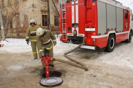
This element is used to collect water and extinguish fire. The method of use depends on its location, either connected to a fire hose or for filling with water. Aboveground hydrates are located above the ground level and are represented by a column with an installation head, on which there is a thread for connecting a hose or a lock. Hydrants are installed in mounted wells to conveniently check the operation of all connections, seals and flanges, this allows for prompt maintenance and monitoring of the system.
3. Pumping stations.
They are used to pump water resources through the system to obtain the required pressure and pressure. There are entire pumping stations, which are built in the form of a small building with a complex of pipelines and power supplies. Such rooms are equipped with devices for calculating the pressure created by the pump and for measuring the discharge of water during intake. The location must correspond to the accessibility of use, thereby ensuring the correct functioning of the pumping stations.
Water occupies one of the main places in human life; in order to create comfortable conditions in the home, a water supply system is necessary. In addition, it ensures safety in case of fires and fires by extinguishing them. At the moment, a developed network of water pipelines provides certain guarantees of a successful outcome in emergency situations.