USER MANUAL.
GAS HEATER
SUN FORSE, SUN FORCE L
SUN FORCE +, SUN FORCE L+.
ASSEMBLY
WARNING: Remove packaging material from all parts and identify parts using the included assembly diagram.
Follow the instructions and adhere to the assembly order shown in Diagrams 1-23.
Sun Force/Sun Force L, Sun Force+/Sun Force L+ - schemes 1-4, 11-23
Sun Force/San Force L – scheme 10
Sun Force+/San Force L+ - schemes 5-8.
SAFETY.
1.Follow safety instructions.
Before assembling or using the heater, read the assembly and use instructions. Keep these instructions and refer to them as needed.
This heating appliance should only be used outdoors.
Do not store or use gasoline or other flammable liquids or gas near the heater. It is not allowed to store flammable materials within a radius of 60 cm from the heater.
Do not move the heating device while it is on. The heater should only be installed on a horizontal surface.
Butane cannot be used if the temperature environment less than 5°C.
DANGER: Some exposed parts (reflector, handles and light) may become very hot. Keep children away from the heater.
CAUTION: Strong gusts of wind may cause the heater to topple.
If you smell gas:
Close the gas inlet (gas cylinder valve or regulator),
Put out the flames
If the odor persists, disconnect the regulator from the cylinder, then store the cylinder outdoors and inform the gas cylinder supplier.
After using the heater, always turn off the gas supply by closing the gas cylinder valve or regulator.
2. Gas cylinder.
The San Force and San Force L models work with 6-liter butane or propane cylinders. Models San Force+ and San Force L+ work with butane or propane cylinders with a volume of 6 to 15 liters. The cylinder must be equipped with an appropriate regulator.
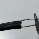
3. Flexible gas hose.
The heater has a connection for a 1.25 m long flexible hose secured with clamps.
A hose designed for propane and butane must be used with the heater. The hose must be replaced if it is damaged or any cracks are found. Do not pull or twist the hose. Keep it at a safe distance from hot parts and components.
FRANCE:
The flexible hose and clamp must comply with XP Standard D 36 - 110. The flexible hose must be replaced if any cracks are found or after the date stamped on the hose has passed.
If the regulator has threaded connection M 20x1.5 instead of a bayonet connection, bring the connection and the gasket supplied with the regulator to the output connection (after the gasket is snug, turn it a quarter turn).
SWITZERLAND, GERMANY, AUSTRIA:
Connecting the flexible hose: To connect the hose to the gas inlet on the heater, tighten the hose not too tight, but not too loose, using two appropriate wrenches:
14 mm spanner to hold gas inlet connection,
Use a 17mm wrench to tighten the hose washer.
4. Check for leaks.
Work outdoors, at a safe distance from flammable materials or open flames. Do not smoke. DO NOT USE FIRE TO DETECT LEAKS.
4-1. Before installing the top part on the optical tube.
Make sure that the control units are set to the “off” position (“OFF” on the heater and “-” on the lantern).
Insert the flexible hose into the gas inlet tube on the heater and the regulator without inserting the hose into the optical tube.
Attach the hose clamp to the flexible hose on the heater.
Attach the hose clamp to the regulator.
Make sure the regulator gasket is in good condition and in place and connect the regulator to the gas cylinder.
Open gas valve(valve on the cylinder (diagram 13A)) or turn the lever on the regulator (diagram 13B) and press the restart button, if provided.
Apply a soapy solution to test for leaks at the cylinder/regulator/flexible hose/heater connections. The control nodes must remain in the "OFF" position.
If bubbles form, there is a leak.
To eliminate leaks, tighten the washers on the regulator and make sure the hose is attached securely.
If no leaks are found, disconnect the flexible hose from the regulator.
Lower the optical tube as low as possible and fully tighten the ring (24)
Place the device on the table with the gas inlet facing up.
Place the flexible hose into the optical tube and tighten (Diagram 12).
4-2. After installing the top part on the optical tube.
Insert the flexible hose into the regulator hole and tighten the clamp.
Stop the gas supply (valve on the cylinder (diagram 13A) or turn the lever on the regulator (diagram 13B)) and press the restart button, if provided (according to the instructions for using the regulator).
Apply a soapy solution to test for leaks at the cylinder/regulator/flexible hose/heater connections. The adjustment units must be closed.
If a leak is detected, repeat the procedures in Section 4-1.
DANGER: NEVER OPERATE THE HEATING UNIT IF THERE IS A LEAK.
Stop the gas supply using the valve on the cylinder or the regulator knob.
OPERATION AND USE.
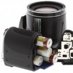
Installing or replacing a battery (not supplied) in the ignition coil (diagram 14).
Turn the coil over and remove the battery from it.
Insert the battery (type LR 03 AAA) into the socket according to the polarity indicated on the case (“+” to “+” and “-” to “-”).
Place the spool in place (14), making sure it fits snugly into the slots.
Heater operation.
If the lantern is not in use, turn on the gas supply using the valve on the cylinder (diagram 13A) or by turning the regulator knob (diagram 13B) and turn it on again if necessary.
Turn on the heater by turning the control knob (21) counterclockwise until it stops.
Press the ignition button (B) and at the same time turn the control knob (21).
Once ignited: release the ignition button but hold the control knob (21) for 15 seconds.
Release the control knob: the heater should operate at full power.
If the burner goes out: repeat the above procedures.
2-2. Ignition of the burner manually.
Start the process as stated in the previous section, but instead of pressing the ignition button, hold the lit match (C) to the top of the glowing screen.
After the fire has occurred, remove the match.
2-3. Shutdown heating device.
Turn the knob (21) clockwise to the “OFF” position.
NOTE: The heater is equipped with two safety mechanisms.
The first safety mechanism automatically stops the gas supply to the burner if the burner flame is uneven.
The second safety mechanism automatically stops the gas supply to the heating device if the device is installed at an angle exceeding 45° relative to the vertical, or if it overturns and falls to the ground.
3.Adjusting the height and position of the reflector.
For greater convenience, the reflector (22) on the heater can be adjusted in height and position to direct the heat where it is needed.
Protect the burner from wind by turning the heater so that the reflector is a screen.
3-1. Height adjustment.
Loosen ring (24), raise or lower top tube to place it in the required position, then tighten the ring (24).
3-2. Position adjustment (diagrams 20-21).
DO NOT TOUCH THE REFLECTOR WITH YOUR BARE HANDS AS IT MAY BE VERY HOT. Use the handle (23) to rotate the reflector vertically to the desired position.
ALWAYS USE THE HANDLE TO INSTALL THE REFLECTOR.
Removing or replacing the gas cylinder.
THE GAS CYLINDER SHOULD ONLY BE REMOVED OR REPLACED OUTDOORS, AT A SAFE DISTANCE FROM FIRE, POSSIBLE SOURCE OF SPARKS (CIGARETTE, ELECTRIC HEATERS, ETC.) AND FLAMMABLE MATERIALS.
4-1. Models Sun Force/San Force L.
Make sure the cylinder valve or regulator knob is closed.
Lift the cylinder cap (12) and place it with the retaining hook downwards until it is completely free. gas cylinder(Scheme 10).
Connect the regulator to the gas cylinder (check the gasket on the regulator).
Replace the gas cylinder cap without covering the hole opposite the regulator.
4-2. Models Sun Force+/San Force L+.
Make sure the cylinder valve is closed.
Loosen the 4 clamps and remove the front cylinder cover (8) (Diagram 8B).
Disconnect the regulator from the gas cylinder.
Remove the gas cylinder from the base of the heater.
Install a new gas cylinder.
Connect the regulator to the gas cylinder (check the gasket on the regulator)
Replace the front cover (8) and tighten the clamps (Diagram 8A).
5. Installation of the heating grid.
Lift (A) the roller (17) and secure it with a quarter turn.
Lower the glow grid (16) onto the burner, with the larger diameter hole facing down; Place the bushing in the groove (B) on the burner.
Return the roller (17) to its original position and install the glow grid into the grooves (C) on the roller.
6. Using a flashlight (diagram 16) (only models with flashlights).
CAUTION: After burning, the glow grid becomes very fragile, so do not touch it, it may break easily.
Do not use a flashlight with a broken mesh as there is a risk that the glass will break. Replace the heating grid only with a suitable CAMPINGAZ® mantle/
Remove the damaged mesh and clear any debris, then install following the above procedures.
6-1. Ignition of the flashlight using electronic ignition.
If the heater burner does not work, open the gas supply (cylinder valve or regulator knob).
Turn on the gas supply by turning the control knob (20) counterclockwise approximately ¼ turn (towards “+”).
Press and hold the ignition button (B) until the light comes on.
Then release.
If the lantern fails to light after several attempts, make sure there is gas in the cylinder.
6-2. Lighting the lantern manually.
Apply a match or lighter (C) to the gap between the glass and the body, then gradually increase the gas supply by turning the handle (20) counterclockwise.
6-3. Brightness adjustment.
The brightness of the flashlight can be adjusted by slowly turning the knob (20) in the “+” or “-” direction.
6-4. Putting out the lantern.
Close the valve by turning the handle (20) clockwise until it stops (“-” in the direction of the arrow).
7. Replacing the lampshade.
MAKE SURE THE HEATER IS TURNED OFF AND COOL.
Remove the cover (19) from the top of the lampshade (18).
Carefully remove the broken lampshade.
Install the new lampshade and clamp the cover onto the top (Diagram 17).
8. Replacing the glow grid.
See section “Installing the Heat Grid”.
9. Maintenance.
9-1. Checking the flexible hose between the valves and the heater burner.
Once a year, check the condition of the hose (which has no time limit).
For this:
Disconnect the regulator from the cylinder,
Lower the cover as low as possible (tighten ring (24) fully),
Remove the control knobs (20) and (21),
Install the reflector vertically,
Unscrew 5 screws (25) - diagram 22 and remove the flange,
The flexible hose becomes visible.
Make sure the flexible hose is in good condition and has no cracks, breaks or marks.
If you find any damage to the hose, return the heater to the supplier.
CAUTION: DO NOT ATTEMPT TO REPLACE THE HOSE YOURSELF.
If there is no damage, install the flange and secure it with 5 screws (25).
9-2. Flexible hose between the regulator and the top of the heater.
Once a year, check the condition of the flexible hose and replace it if defective (or if the expiration date has expired, see section 2-3.)
Check for gas leaks in accordance with section 4.
10.Storage and malfunctions.
The heating device can only be stored after it has completely cooled down:
Make sure the gas supply is closed on the gas cylinder (cylinder valve or regulator knob in the closed position).
IMPORTANT: Store the heater and gas cylinder in a cool, dry and well-ventilated area.
DANGER: Keep away from children and never store in basements. Propane gas cylinders must be stored outside residential premises.
For long-term storage of the heating device:
Remove the cylinder from the heating device,
Place the reflector in a vertical position and cover it.
Important! Please read this Owner's Manual carefully and completely before assembling, starting, or servicing the heater. Improper use of this heater can result in serious injury or death due to burns, fire, explosion, electric shock or poisoning carbon monoxide.
Be sure to heed all warnings. Please save this manual for future reference. It will be your guide to the correct and safe operation of the heater.
Safe Operation Standards
BEKAR brand gas heaters are highly efficient and reliable products that meet the requirements of Russian and European safety standards. However, the following guidelines for safe operation must be observed:
- Do not use the heater where vapors of gasoline, acetone, paint thinners, alcohol or other flammable substances, or explosive substances are present.
- When using the heater, comply with all local laws and regulations in addition to national laws.
- When delimiting the heated space into separate zones using partitions made of materials like tarpaulin and canvas, impregnated fire retardant compounds, ensure a minimum distance of three meters between these materials and the heater. All partitions must be securely fastened.
- Use the heater only in well-ventilated areas, see section "Ventilation Requirements".
- Use the heater only in places where there is no heavy dust.
- Use only the voltage and frequency indicated on the heater rating plate located on its body.
- Use only a grounded power cord with a three-prong plug.
- Maintain the following minimum distances from the heater to combustible materials:
- from the hot air outlet side - 3.0 meters;
- from above - 2.0 meters;
- behind and from the sides - 1.0 meter. - To prevent fire, a running or hot heater must be placed on a level, stable surface.
- Keep children and animals away from the heater.
- Do not leave a running heater plugged in.
- Be careful: a heater equipped with a room thermostat will turn on and off automatically at random times.
- Do not use the heater in living or sleeping areas.
- It is prohibited to cover or cover the inlet and/or outlet of the heater.
- It is prohibited to move, lift or service a heater that is hot, running or plugged in.
- The premises where heaters are installed must be equipped with fire extinguishing means.
- Do not attach any hoses to the inlet and/or outlet of the heater. It may weaken air flow passing through the heater and increase the carbon monoxide content in the exhaust air.
- Do not violate the established sequence of turning off the heater.
- Do not cover the heater while it is running.
- Do not use a heater installed below ground level, as propane is heavier than air and if there is a leak, it will leak to the lowest level.
- Keep the heater away from drafts, spray water and rain.
- Check the heater for damage after each use. Do not use a damaged heater.
- Use only propane gas, 13 RUR.
- Do not allow the gas cylinder to heat up to temperatures above 37°C.
- Use only the hose and gas pressure regulator included in the package.
- Keep the heater at least two meters away from gas cylinders. Never point the heater at a gas cylinder.
- Do not make any changes to the heater design. Do not use a technically modified heater.
- This heater must use the spare parts provided during disassembly. Incomplete spare parts can cause serious injury and accidents.
Carbon monoxide poisoning is deadly!
The first signs of carbon monoxide (carbon monomonoxide) poisoning resemble flu symptoms - headache, dizziness or nausea. If you experience these symptoms, your heater may not be working properly.
Immediately: 1. Turn off the heater.
2. Ventilate the room.
3. Get out into the fresh air.
Contact the service center!
Staff
- Each piece of equipment must be assigned a specific employee. It is unacceptable for random people to service heaters.
- Personnel whose functions include servicing heaters must be qualified and know the requirements of this Manual, Rules technical operation and labor safety requirements in the gas industry.
Description of design
The product is a direct-acting blown gas heater that fully utilizes the heat of burnt gas by mixing hot combustion products with blast air.
Areas of use
- For heating workshops and utility rooms.
- During construction and performing installation and finishing works.
- As an additional heater for non-residential premises.
- Everywhere and always, when creating a heating network is expensive and impractical, as well as during seasonal work.
Product composition
The main design elements of the heaters are presented in Figures 1, 2 and 3.

Fuel
FUEL CHARACTERISTICS
- As a source of thermal energy in gas air heaters, a mixture of liquefied hydrocarbon gases is used, consisting mainly of propane (C 3 H 8), butane (C 4 H 10) and pentane (C 5 H 12); The main component of this mixture is propane.
- To ensure safety when using liquefied gases, the user of a gas air heater must take into account the following properties:
- liquefied hydrocarbon gases under environmental conditions are in a gaseous state, and with a slight increase in pressure (without decreasing temperature) they turn into a liquid state. This property allows you to store and transport liquefied gases in containers and cylinders with the conveniences characteristic of gases;
- the vapor pressure of liquefied gases in the cylinder depends on the ambient temperature;
- in the gaseous state, hydrocarbons are 1.5 ... 2.0 times heavier than air, due to which liquefied gas vapors accumulate in recesses, pits and other lowest points of the room, making it difficult to weather them;
- low viscosity prevents gas leaks;
- low explosive limits: when the air contains 2% liquefied gas (lower explosive limit), the resulting gas-air mixture becomes explosive and continues to remain so until the concentration of liquefied gas in it increases to 10% (upper explosive limit); when the liquefied gas content in the air is more than 10%, the gas-air mixture is not explosive, but flammable;
- when the outside temperature rises, the liquefied gas in the cylinder expands significantly, so the gas cylinder should not be allowed to heat above a certain temperature (37°C);
- liquefied gases are odorless. For timely detection of gas leaks, it
odorize, i.e. add a special substance - an odorant;
- all hydrocarbon gases, replacing oxygen in the air, have asphyxiating properties.
A decrease in oxygen content to 22% is deadly;
- ingress of the liquid phase of liquefied gas onto open areas skin leads to severe
frostbite.
- Propane as a liquefied gas can be used at temperatures down to - 30°C. At lower temperatures, propane vapor condenses and gas supply stops at a temperature of -42°C. Technical butane vapor begins to condense at - 0.5°C. This property makes it impossible to use butane in winter period in cylinders installed outdoors. The gas remains in the cylinder in a liquid state, there is no evaporation, and, therefore, there is no necessary pressure in the cylinder at which the gas pressure regulator can provide the minimum permissible gas flow.
PROVIDING FUEL
- The user must equip the gas heater with a 50 kg gas cylinder(s) filled with propane. It is unacceptable to use gas cylinders of smaller capacity.
- The amount of propane available for use is determined by two factors:
- amount of propane in the cylinder(s);
- temperature of the cylinder(s). - When operating the heater at low ambient temperatures or at maximum heat output, gas cylinders may become cool due to an increase in the rate of gas evaporation, which can lead to a drop in pressure in the cylinder(s) and poor combustion. In this case, it is recommended to perform parallel connection cylinders, as shown in Figure 4, using a special “tee” (purchased at an additional cost).
Fig.4 Parallel connection of gas cylinders
- Below is the number of 50-kilogram cylinders required to operate a gas air heater with a thermal power of 30 kW or more.
MAKING CONNECTIONS
1. Provide a propane supply system, see section “Fuel. Providing fuel."
2. Check the presence of a gasket under the union nut of the gearbox. Connect the reducer to the gas cylinder using a union nut (Figure 5), tighten the nut with a wrench. Important: When placing cylinders outdoors, install the reducer so that the adjustment knob (if equipped) is turned down, this will prevent damage to the reducer due to adverse weather conditions.

Fig.5 Connection of the reducer with a gas cylinder.
Important: To increase the operating safety of gas air heaters, it is recommended to install them on the gas supply line "gas fuse"
, purchased for an additional fee, shuts off the gas supply when a leak appears in the gas supply system. When connecting heaters to the gas supply system, install a gas fuse between the fittings of the reducer and the gas supply hose to the heater. When PREPARING TO TURN ON, press the guard head gas fuse and fix it in the lowest position (this operation must be done every time the gas pressure drops - for example, after replacing a used gas cylinder). If the gas fuse has tripped, stopping the gas supply and stopping the air heater, there is a leak in the gas hose. In this case, follow the steps described in the CARE section. A LEAK. After eliminating the gas leak during PREPARATION FOR STARTING ON, turn the gas fuse into the working position by pressing its head - the guard..
3. Connect the hose to the heater power connection (Fig. 6). Secure the connection with a wrench.

Fig.6 Connection of the hose to the heater.
4. Open the valve on the gas cylinder.
5. Set the gear handle (if the gearbox is adjustable) to the gas pressure value
corresponding to the operating range of the heater (see section TECHNICAL
CHARACTERISTICS).
6. Make sure there are no gas leaks using the soaping area - applying liquid
soap or soap solution to the joints.
Warning! Never use an open flame to detect leaks.
Use the soaping method - applying a soap solution to all joints.
The bubbles that form will indicate gas leaks.
Take immediate action to repair all leaks.
7. Close the gas cylinder valve.
REPLACING THE GAS CYLINDER
Change gas cylinder(s) only where there is no open flame. Extinguish all sources
flames, including those on duty. Use only propane, 13P.
Sequence of operations when replacing a gas cylinder:
1. Close the valve on the gas cylinder(s) you are replacing.
2. Disconnect the reducer from the cylinder(s).
3. Connect the reducer to the new gas cylinder. Tighten the union nut tightly.
4. Check all connections for gas leaks.
Product contents
The delivery package for gas heaters of all models includes:
- gas air heater;
- hose with reducer;
- user manual;
- packing box, air heaters are supplied fully factory ready for use.
Unboxing
1. Remove all packaging materials used to transport the heater.
2. Remove all items from the packing box.
3. Check the heater for damage during transportation. If there is damage, do not start it yourself - it is dangerous; contact customer service.
Recommendation: Save the packing case and packing materials; they may be needed in the future for storage or when transporting the heater.
Principle of operation
FUEL SUPPLY SYSTEM
The gas pressure regulator (reducer) is attached to the propane cylinder, see the section “FUEL. MAKING CONNECTIONS” or can be mounted on the body of the heater itself. When opening the gas cylinder valve, gas is supplied to the combustion chamber nozzle after opening the gas valve, which has electromagnetic principle or manually opened by pressing the valve button.
AIR SUPPLY SYSTEM
The engine rotates the fan, under the influence of which the air moves inside the combustion chamber, forming a gas-air mixture, and around it. After combustion of the gas, a stream of clean hot air is formed at the heater outlet.
IGNITION SYSTEM
Ignition of the gas occurs from a spark discharge between the electrodes - igniters, the voltage to which is supplied automatically from the control unit when the heater is turned on or from the ignition element when its button is pressed manually.
FLAME CONTROL SYSTEM
This system turns off the heater if the flame goes out. In this case, gas combustion and heat production stops, however, the fan motor continues to operate, providing purging and cooling of the combustion chamber. The basis of the control system is a temperature sensor, the signal of which shuts off the gas supply valves.
Ventilation requirements
Before starting the heater, it is necessary to provide, and in subsequent use maintain, the area of flow of fresh outside air through two ventilation openings (for air inlet and outlet) (S windows) in accordance with the formula:
S window = W max × 25 (cm3);
where W max is the maximum thermal power of a heater of a given brand, kW.
The minimum total window area is 250 cm3.
One vent should be at floor level, the other - under the ceiling. Non-compliance minimum requirements to ventilation of the room can lead to CARBON MONOXIDE POISONING. Ventilation of the room with fresh outside air must be ensured before starting the heater.
Terms of use
Check the completeness and accuracy of compliance with the requirements and regulations set out in the “Safe Operation Standards” section of this manual. Do not use the heater if at least one of the requirements is not met.

Fig. 7 Control panels for air heaters with a manual gas ignition system. Switching sequence
PREPARATION FOR LAUNCH
- Place the heater on a stable and level surface.
- Make sure the heater is away from strong drafts.
- Connect the heater's power cord to a single-phase network with a voltage of 220...240 volts with good grounding.
Note: If necessary, use a three-prong grounded extension cord that meets the following requirements:
- For a cord length of up to 30 m, the wire cross-section must be at least 1 mm2.
- For a cord length of up to 60 m, the wire cross-section must be at least 1.5 mm2.
- Open the cylinder valve and set the gas pressure regulator to the desired heat load position.
Inclusion
Models P10M, P20M and P30M with a manual gas ignition system.
The heater controls are shown in Figure 1. The sequence of operations for turning on the heaters:
1. Turn on the blower fan by pressing the power switch (A) (Figure 8), setting it to the “ON” position and make sure that the fan is working.
2. Press the gas valve button (B) and, holding it down, press the ignition button (C) several times until the gas ignites.
3. Release the gas valve button (D). If after this the combustion stops immediately, wait one minute, then repeat the ignition procedure described above (steps 1 - 2), while holding the gas valve button a little longer.
EMERGENCY SHUTDOWN
In the event of a sudden or unauthorized power outage during operation of the heater, resulting in a fan stop, fuel supply interruption and other reasons, the protection system will automatically close the gas valve within a few seconds to prevent gas leakage. The fan motor may continue to operate.
Restarting the heater:
1. Disconnect the heater from the mains.
2. Find out the reason for the automatic protection operation.
3. Eliminate the reason for the automatic protection operation.
4. Wait at least 30 seconds after the heater stops.
5. Plug in the heater.
6. Press the “RESET” unlock button (if available).
7. Repeat the operations in the “TURN ON” section.
Storage
PREPARATION FOR STORAGE
Turn off the heater. See “Terms of Use. Shutdown."
- Disconnect the hose from the heater.
- Disconnect the reducer from the gas cylinder.
HEATER STORAGE
- Store the heater in a dry place.
- Keep the heater in working position.
- Ensure that the storage area is free of corrosive fumes.
- To protect the heater from dust, cover it with a cover (available at an additional cost) or place it in a shipping box.
STORAGE OF GAS CYLINDERS
Store gas cylinders in an upright position in rooms specially equipped for these purposes in accordance with the Safety Rules in the Gas Industry and the Rules for Technical Operation and Occupational Safety Requirements in the Gas Industry.
Recommendations: To ensure uninterrupted operation of the heater for heating season conduct a seasonal Maintenance; contact the service center.
Transportation
If it is necessary to transport the heater:
- Carry out the operations outlined in the “Storage” section. Preparation for storage."
- Protect the heater from accidental damage during transportation by using a shipping box with packaging materials in which the heater you purchased was delivered.
- When transporting, maintain the working (horizontal) position of the air heater.
- When transporting a gas cylinder, comply with the requirements set out in the Safety Rules in the Gas Industry and the Rules for Technical Operation and Occupational Safety Requirements in the Gas Industry.
Care
COMPOSITION OF OPERATIONS
Maintenance performed by the heater user includes the following operations:
1. Clean the heater once a year or as needed to remove dust, dirt and debris.
2. Inspect the heater before each operating session.
3. Check the connections for gas leaks; eliminating leaks when
detection.
4. Inspect the hose with reducer before each work session. If the hose is cut, frayed or damaged, replace it. Use only a hose with a reducer recommended in this manual.
Important! Any maintenance operations must be carried out with the cold heater inoperative, disconnected from the network and from the gas cylinder.
To perform other heater maintenance operations, for example, inspecting and cleaning the fan or monitoring the control unit and adjusting the igniter electrode, or in case of difficulties when performing the above heater maintenance operations, contact the service center.
GAS LEAK
Warning! If a leak is detected, turn off the gas supply immediately
By tightly closing the gas cylinder valve. Ventilate the room.
Wait another five minutes after the smell of gas disappears.
Proceed further according to the diagram below.
1. Set the network switch to the “OFF”, “O” position.
2. Unplug the heater power cord from the electrical outlet.
3. Apply soapy water to the hose and all connections between the gas cylinder and the heater power connection.
Warning! NEVER USE AN OPEN FLAME TO DETECT GAS LEAKS!
4. Open the gas cylinder valve. The bubbles that form will indicate the location of the leak.
5. Close the gas cylinder valve.
6. Ventilate the room until the smell of gas disappears completely.
7. Fix the leak by repair.
8. Wait five minutes after the propane smell disappears before turning it back on.
heater. If you cannot repair the leak yourself, contact the service center.
| The fan is not working. | No voltage in networks. Broken power cord or defective power plug. Impeller jammed fan The electric motor is faulty. |
Check for voltage at fan motor terminals. Network wire or replace the plug. Release the fan impeller. Replace the electric motor. |
| When you press the button ignition no spark. |
Incorrect position of electrodes. The ignition unit and/or electrodes are faulty. |
Check and install electrodes Right. Check and connect correctly or replace. |
| Gas is not supplied to burner |
Gas valve closed balloon. The gas cylinder is empty. The nozzle is clogged. Leak in supply hose gas or at connection points. |
Open the gas cylinder valve. Replace the cylinder. Remove the nozzle and clean it. Using soap suds, find the location of the gas leak and eliminate it malfunction. |
| There is gas ignition, but immediately after the gas supply valve released, the flame goes out. |
Thermal sensor failed warm up. The safety valve has tripped thermostat for reason overheating of the unit; possibly impeller fan is jammed. |
Turn on again while holding pressed gas valve button position a little longer. See item "Fan does not works". |
| The heater turns off while working. |
Too much consumption fuel. Unit overheating unsatisfactory reason fan operation. Reducing gas supply due to education on frost balloon. |
Check for correct operation |
| Unstable combustion gas (flame with white and bright yellow tongues). |
Insufficient air flow into burner air heater. |
Excessive gas consumption. Check the inlet pipe heater - possible access the air is disturbed by strangers items. Reduce gas pressure. |
Guarantee
The manufacturer guarantees proper work the device during the warranty period - 12 months from the date of sale by the store. Documents confirming the purchase and inspection of equipment by a certified specialist are required when making claims.
The manufacturer reserves the right to terminate or limit the warranty in the absence of the specified documents, as well as in the case of obvious external mechanical damage to the product.
Your customer service
Salesman
Date of sale:
Buyer:
Your service organization:
The product was inspected by: _______________________________________
Please indicate your full name and qualification number (category)
| E P  2. Clothes or other things should be kept away from the heater. Besides fire danger, this will also reduce heat transfer.  4. Do not move the heater while it is on.  3. Do not place the heater close to curtains or furniture.  5. Do not move the heater along a wall or near flammable materials. Minimum distance to the heater should be: 20 cm from the back and sides and 1.5 m in front. Thermal radiation should be directed to the center of the room. Since the heater is equipped with wheels and can be easily moved, when using it you must pay attention Special attention if you have small children or pets at home. 6. In case of gas leak, the heater turns off immediately. Do not turn off the regulator on the cylinder until all the flames have gone out. Check all gas connections with soapy water. In areas of gas leakage, the soap solution will bubble. If no leak is found, contact your dealer. |


mobile gas heater
This is a universal and mobile heater that will allow you to quickly and economically warm the room you need.
1. How to install a cylinder.
A) Remove the heater from the box.
b) Remove the back panel.
V) Unscrew the shipping bolts inside the heater housing that hold the removable panel.
G) The gas cylinder must be positioned so that the valve opening faces outwards for easy access to the tap.
d) Screw the reducer onto the gas cylinder counterclockwise, with the valve in the closed position.
2. Turning on the gas heater.
A) Open the gas cylinder valve by turning it counterclockwise 1-1.5 degrees.
b) Press and turn the control knob to position I (minimum)
V) Simultaneously press the ignition button several times until a flame appears.
G) Hold the control knob for another 10-15 seconds after ignition. If the flame goes out when you release the button, repeat again.
3. Replacing propane cylinders.
Replacement of propane cylinders is carried out with the flame extinguished. Only propane gas is used.
A) Close the propane valve on the gas cylinder tightly.
b) Remove the hose with regulator from the cylinder.
V) Connect the hose with the regulator to the new propane tank. Tighten tightly.
G) Check all connections for leaks.
4. Gas heater with electrical element heating
Models with the EL prefix are equipped with an electrical element with a power of 3x400 W. This allows the heater to be used even in the absence of gas.
Take a wire with a plug (230 V – 50 Hz) and connect it to an appropriate power source.
To enable electric heater use the switch on the control panel of the device.
5. WARNING
If you suspect the heater is leaking, turn off the cylinder valve and contact your local gas specialist. DO NOT attempt to locate the source of a leak with an open flame, but if necessary, locate the leak by smell or using soapy water.
| Regulator position | Rated thermal power kW | Nominal fuel consumption |
| At power level III | 4.20 kW | 298 g/h |
| At power level II | 2.60 kW | 185 g/h |
| At power level I | 1.20 kW | 085 g/h |
7. Warranty service
If hidden manufacturing defects are detected in the product, the buyer has the right to have them eliminated free of charge within 12 months from the date the device is put into use by the buyer (in accordance with the date of sale specified in the warranty card and cash receipt). Warranty service is performed at points authorized by the manufacturer service.
Warranty service is not provided in the following cases:
Violation of operating conditions
Mechanical damage
Exposure to and ingress of foreign objects, liquids, insects, cement dust, etc.
Incorrectly completed warranty card (missing date of sale and/or seller’s seal) as well as missing accompanying documents(checks, receipts)
Traces of the device being opened by the buyer or other unauthorized persons.
Using the wrong type of gas or poor gas quality
| Malfunction | Probable Cause | Elimination method |
| The burner burns weakly or does not ignite | 1. Insufficient pressure gas in a cylinder. 2. The valve on the propane tank is closed. 3. Defective gas valve. | 1. Check the propane tank pressure. Replace the cylinder if necessary. 2. Open the valve on the propane tank. 3. Eliminated by specialists from repair shops. |
| No ignition spark | 1. The electrode is damaged or out of order. 2. Igniter wire is disconnected or poorly connected. 3. The igniter wire is damaged. | 1. Replace the electrode. 2. Connect or secure the wire. 3. Replace the wire. |
| Burner operates intermittently | 1. There is not enough gas in the cylinder 2. Burners are clogged | 1. Refill or replace the cylinder 2. Clean the burner when it has cooled down |