


Conventionally, the installation diagram (we are considering the Victrix 50 boiler as an example) can be divided into several connection stages:
- safety kit;
- storage boiler;
- solar collector;
- hydraulic separator.
Let's look at each stage in detail.
Safety kit
When connecting a boiler with a power of more than 35 kW, European legislation requires paying closer attention to safety issues. Therefore, a special safety kit is provided, which includes a safety thermostat, a maximum water pressure switch (4 bar), a pressure gauge and a system filling valve (sleeve for connecting the thermal cylinder of the gas shut-off valve).
There are also fittings for connecting expansion tank and a sleeve for an immersion alcohol thermometer. The pressure switch and overheating thermostat have manual unlocking and are connected in series to the boiler power circuit (Fig. 2). Operation limit safety devices adjustable to 3 bar and 105 °C, respectively. This kit allows you to produce a compact, fast and reliable installation safety devices and also guarantees reliable protection from emergency situations under any circumstances.
Storage boiler
Since the boilers are single-circuit, it is proposed to use a storage type boiler to meet the needs for hot water. Several standard sizes of boilers are offered, with a capacity from 80 to 200 liters. Boilers have a rectangular body white. The material for the body and coil of the boiler is food grade stainless steel. high quality. To reduce heat loss, the boiler is enclosed in highly efficient polyurethane foam insulation.
The boilers are equipped with spiral heat exchangers with a large heat exchange surface, which are connected in a counterflow circuit (Fig. 3). This allows you to quickly heat the accumulated water supply. To ensure large volume cooking hot water, you can use two 200 liter boilers, in which the coolant and sanitary water circuits are connected in parallel. To connect the boiler to the boiler, you must use a special kit, which consists of adapters and three way valve. As in all others mounted boilers, operation in hot water supply mode is based on the principle of strict DHW priority.
Connecting solar collectors
A special feature of 200-liter boilers is the ability to work with solar collectors. In Fig. Figure 4 shows an example of connecting solar collectors to a heat supply system based on a condensing boiler. High-quality solar collectors and a home heating system coordinated with them make it possible to consider the economic use of solar energy as a necessary condition for building an effective system.
At our latitudes, the total radiation (reflected and direct) in optimal conditions(cloudless clear sky, mid-day) is a maximum of 1000 W/m2. Solar collectors, depending on their type, allow the use of up to 75% of the total radiation. It remains only to note that from our point of view the combination of condensing boiler + solar collector(heat pump) - the most promising direction further development autonomous heat supply systems.
Hydraulic separator
Since the boiler is designed to carry a significant heat load, this requires the presence of separate heating system circuits with zone control. Therefore, the issue of independent control of circuits becomes relevant. There is a possibility of a change in the amount of coolant circulating through the boiler, which adversely affects its hydraulic mode.
A natural solution in this situation is the use of a hydraulic separator (hydraulic arrow). At the same time, a transition is made to pipes of larger diameter, which makes it possible to connect the “hydraulic arrow” directly to the supply and return distribution manifolds. For one boiler, a compact solution for this unit is proposed, in the form of a rectangular pipe (Fig. 5).
This unit is located directly under the boiler, which makes it possible to significantly reduce the dimensions of the installation. Since the collector is installed horizontally, to remove sludge from the heating system, it is necessary to install a sediment filter on the return line, in front of the collector.
It is the main element of the chimney system. Used on straight sections to achieve the required height.
There are three types of length sizes - 250, 500, 1000 mm. , which makes it possible to select elements in accordance with the design configuration. Chimneys of the “Sandwich” type consist of an internal welded pipe(various steel grades (AISI 430, 304, 321) of different thicknesses and an outer pipe of larger diameter made of matte or polished (mirror) stainless steel AISI 430 grade 0.5 mm thick or galvanized steel. A layer of insulation is laid between the pipes - non-flammable insulating material based on basalt rocks.

Throttle valve
This is a chimney element used to regulate draft by partially blocking smoke channel, and also as a damper on an unused fireplace with an open firebox to prevent the outflow of warm air from the room through the chimney.
It is a pipe with a built-in rotary valve and a handle brought out.

Mono-thermo transition
This is a chimney element used when connecting chimney systems of various types or when it is necessary to change the diameter of the smoke duct.
The transition is installed at the junction of parts of the chimney system with different diameters. As a rule, when moving from a smaller diameter to a larger one, in situations where several heat generators are connected to the main chimney channel at different levels


The outlet is the main element of the chimney system, allowing you to change the direction chimney in cases where it is necessary to bypass an obstacle, or turn the chimney in the desired direction. Bends are made from cylindrical sectors connected at a certain angle.

Tee 90°
Tee 90 consists of two cylindrical elements connected at an angle by spot or seam welding.
When installing a tee at the turn of the chimney from a horizontal or inclined position to a vertical one, a plug or condensate drain plug is installed at the bottom of the tee that closes the entire system.
It is preferable to use a 90° tee in dry mode, since when the flow of gases slows down during a sharp turn, active condensation may occur.

Tee 45°
A 45° tee consists of two cylindrical elements connected at an angle using spot or seam welding.
When installing a tee at the turn of the chimney from a horizontal or inclined position to a vertical one, a plug or condensate drain plug is installed at the bottom of the tee that closes the entire system.
The 45° tee provides best conditions traction than a 90° tee, since it has a larger angle (135°) of rotation.

This is a chimney inspection element designed to diagnose the condition of the smoke channel and clean the chimney by removing products of incomplete combustion of fuel (soot). The inspection makes chimney maintenance easier.
As a rule, the inspection is installed at the base of the chimney, below the connecting tee, as well as on horizontal sections connecting chimney more than 2 meters long.
The revision is a modification of a 90° tee equipped with a special cover secured with a pipe clamp. The revision consists of two cylindrical elements connected at right angles.

Stub
It is installed at the bottom of the tee to collect soot and condensation, and can also be removed to remove foreign objects from the chimney.

Plug with condensate drain
Designed to collect and remove condensate products from the smoke duct. Consists of a pipe element, a conical element or a tray with a hole, connected to each other. The hole is designed to drain condensate and is equipped with a pipe.

Conical end
If special-purpose elements are not installed at the mouth of the chimney, a conical end should be installed to protect the insulation from precipitation.
Thanks to the closure of the inner pipe and the upper edge of the truncated cone, the access of atmospheric precipitation to the insulation is blocked.

Used as the end of a chimney to protect it from precipitation.

Thermo-thermo transition
These are chimney elements used when connecting chimney systems of various types or when it is necessary to change the diameter of the smoke duct.
Transitions are installed at the junction of parts of the chimney system with different diameters. As a rule, when moving from a smaller diameter to a larger one, in situations where several heat generators are connected to the main chimney channel at different levels.
E. Chernyak
So that the consumer remembers the boiler only during the scheduled maintenance, it is not enough just to choose high-quality and reliable equipment. It is important to install it correctly, because often illiterate installation leads to failure of the equipment and prohibition of its delivery for warranty service. This is especially true when installing expensive condensing equipment
General principles
Collateral correct installation boiler and its further normal operation is the competent design of the entire heating system. The point is that, for example, significant efficiency and operating comfort of equipment cannot be achieved without installing thermostats. Modern technologies allow you to create zoned heating systems. In this case, in each heating zone under sensor control room temperature its own microclimate is maintained.
The temperature of the condensation heat exchanger must be below the dew point of the exhaust gases, and the formation of chemically active liquid condensate on its surface is not only normal, but also necessary. Moreover, it must be diverted outside and neutralized in one way or another. Combustion product exhaust systems must be made of corrosion-resistant materials.
When installing systems with condensing boilers, it is important to accurately calculate the heat loss of the building and design heating taking into account the use of such equipment.
To reduce the required coolant temperature, additional measures to reduce heat loss are important - thermal insulation of enclosing structures, installation of windows with multi-layer glazing.
Boiler space
Guided by regulatory documents, determine suitable premises. At the same time, options for installing a boiler in bedrooms, bathrooms, common-use corridors, rooms with insufficient ceiling height, small volume and lack of windows (transoms, vents) are not accepted in advance. Most suitable places are kitchen or separate non-residential premises of sufficient volume, with opening windows or vents (Fig. 2). The presence of sewerage in the premises is highly recommended.

Rice. 2. The boiler room must have opening windows
When hanging the boiler on the wall, you usually use the hooks included in the delivery kit. They are fixed to the wall using dowels. Then the unit itself is hung on these hooks. It is unacceptable if the upper edge of the boiler is further away from the wall than the lower edge, that is, in common parlance, “filled up.” For a traditional boiler, a forward tilt of 0.5-1.0 cm per 1 m does not pose a significant danger, but in the case of a condensing boiler the situation is different. After all, the condensation module is rigidly fixed to the frame. During boiler operation, condensation of water vapor from combustion products occurs in the secondary chamber of the module (economizer section). The resulting condensate is collected in a molded tray and discharged first into a siphon and then into the sewer (Fig. 3).

Rice. 3. Formation and removal of condensate from the condensing boiler module
When the top of the boiler tilts forward, the condensate flows into the primary chamber, comes into contact with the heat exchanger tubes and begins to evaporate intensively. This leads to the shorting of the flame control electrodes to the boiler body and its blocking.
Thus, when attaching the boiler to standard hooks, it is necessary to carefully check the verticality of the boiler and, if necessary, level it. The boiler tilting forward is unacceptable. Also, the boiler must not tilt to the side.
Deviations from the vertical position are checked using a level gauge.
Requirements for chimneys
Most errors during the installation of condensing boilers occur due to violation of the manufacturer’s recommendations or neglect of smoke removal standards.
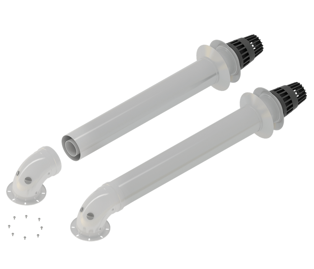
Violations often occur due to the use of coaxial pipes or separate sets from traditional boilers. The materials for the manufacture of coaxial pipes of traditional boilers are aluminum alloys and steel. Their purpose is to withstand high temperatures of combustion products (110°C and above). The specificity of the operation of condensing boilers is low flue gas temperatures in standard modes (40 - 90 ° C), and often below the dew point temperature (57 - 60 ° C, depending on the excess air coefficient). Condensation of water vapor from combustion products occurs not only in the boiler module, but also in the chimney. The condensate has low acidity at pH=4, but with prolonged exposure to aluminum or steel chimney ducts it can destroy them. Therefore, the chimneys of condensing boilers along the exhaust path are made of special polymers (for example, polypropylene) that are resistant to acid corrosion of condensate and can withstand temperatures up to 120°C. For example, the Baxi company (Italy) supplies for its condensing boilers (Fig. 4), the efficiency of which is 108.9%, a plastic coaxial pipe with a tip with a diameter of 60/100 mm and a length of 750 mm. The delivery set includes: coupling and gasket; tip protecting against gusts of wind; decorative stainless steel trim on outer part walls.
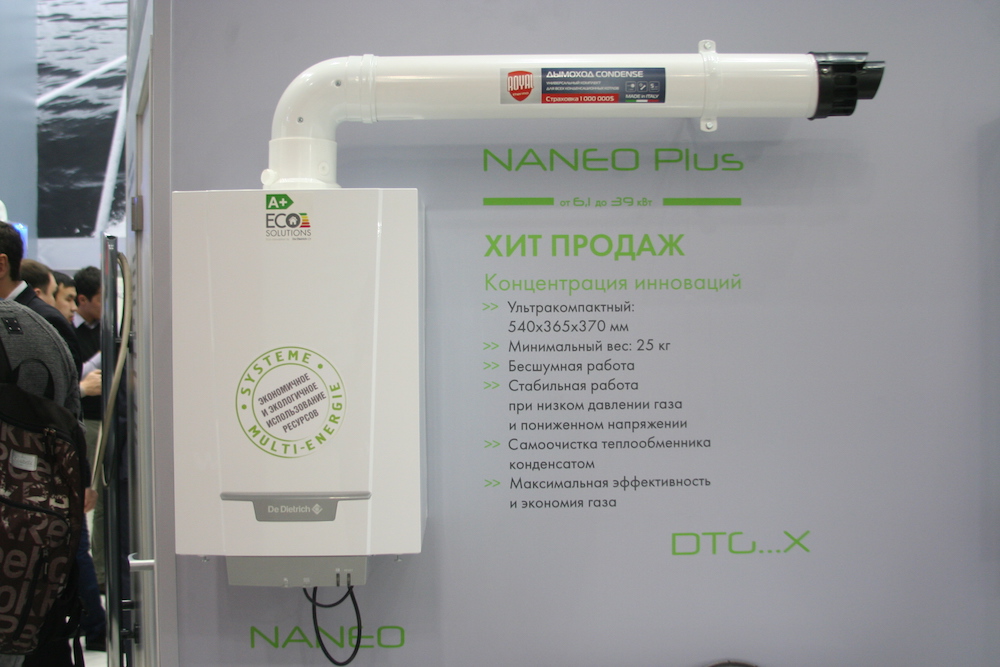
 Rice. 4. Wall-mounted gas condensing boiler
The use of chimney kits from traditional boilers on condensing boilers and vice versa is prohibited.
There are also violations due to use sewer pipes as chimneys. Due to the rather high cost of special chimneys for condensing boilers, there is often a temptation to use sewer pipes, because the low temperature of the flue gases is one of the features of such boilers. The mistake is that sewer pipes are not designed for long-term operation at high temperatures (80°C and above). And the temperature of the flue gases may be higher than this value, for example, when the boiler is operating in DHW mode. In this case, the sewer pipes are deformed, the sealing rings dry out and crack, and the chimney tract ceases to be tight. At the same time, people's lives are at risk and damage is caused to chimneys due to their soaking from condensation and gradual destruction. In this regard, the use of sewer pipes as chimneys for condensing boilers is unsafe and is strictly prohibited.
Incorrect slope of chimney or air intake pipes. Options for installing chimneys of condensing boilers may vary depending on conditions (Fig. 5), however, the basic rule must be observed - the slope of the chimney pipe should facilitate the flow of condensate back into the boiler module. The slope of the air intake pipe should prevent precipitation from entering the boiler body.

Rice. 5. Options for installing chimneys in accordance with the European classification for type C boilers (with combustion air intake from the outside or from a common shaft)
In Fig. 6 are shown schematically the right ways organization of smoke exhaust and air intake during various types chimney pipes. So, in Fig. 6a shows the use of one chimney pipe and the transfer of the boiler to operation with air intake from the room. The elbows (if any) are assembled in such a way as to ensure that condensate flows through the pipe back into the condensation module. It is very important to avoid possible places with a negative slope, where stagnant condensate will collect and disrupt the operation of the fan.
How special case a single chimney is used, which exits straight up from the boiler without elbows. If you exhaust combustion products into an existing (or common for multi-story buildings) chimney (Fig. 6 b), then you need to make sure that this chimney can be used with condensing boilers and has a condensate collector with a siphon at the lowest point. The release of flue gases from condensing boilers into brick chimneys leads to their destruction due to soaking. Release into chimneys made of black steel or aluminum leads to increased corrosion. The most optimal are insulated chimneys made of polypropylene or stainless steel. If the customer has a chimney, for example a brick one, then it can be “lined” polypropylene pipes or a stainless steel pipe.
When assembling the chimney, it is very important to follow the connection order: into the socket with an o-ring, the next section is inserted from above with the smooth side. This allows condensate to flow unhindered back into the boiler module. But often stainless steel chimneys are assembled from scrap materials, and even with gross violations (the lower pipe enters the socket of the upper one), thus, condensate flowing back through the pipe exits through the connections, which in some cases leads to disastrous results. For example, condensate begins to flood the boiler.
When using a standard coaxial kit, it is also necessary to observe the upward slope of the chimney pipe (Fig. 6 c). For low-power wall-mounted boilers, the slope is ensured by the design of the end terminal - when the outer pipe is horizontal, the inner one has an upward slope.
Structurally, it is possible to install a boiler with a single horizontal discharge behind the wall. The slope, as in the above cases, is upward (Fig. 6 d).

Rice. 6. Options for organizing the correct pipe slopes
In Fig. Figure 7 shows diagrams of improper installation of chimney and air intake pipes. In this case, a stagnant zone may form, which interferes with the operation of the fan and leads to blocking of the boiler (Fig. 7 a). If installed as in Fig. 7 b or fig. 7c, condensate flows out in large quantities and freezes to form icicles. The location of the air intake pipe is as shown in Fig. 7 g, will result in hit atmospheric moisture into the boiler body, and then to a boiler blockage or short circuit.

Rice. 7. Incorrect installation chimney slopes
Despite the fact that both the DBN and the recommendations of the manufacturer strictly regulate the distance from the emission terminal to the nearest objects, gross violations of these standards occur quite often. Among the most common are the low level of the coaxial terminal relative to the ground and the short distance between adjacent terminals.
The first is typical for private cottages. Thus, semi-basement rooms are most often allocated for the boiler and related components of the heating system (pumps, collectors, expansion tanks, boilers, etc.). The choice is obvious and correct - useful information is not taken away living area, all components of the system can be hidden and will not interfere with the design of the premises. After all, placing a bulky boiler with piping and a hot water boiler in the kitchen is not a completely aesthetic solution. And although the vast majority of adapted premises have chimneys and ventilation ducts, there is a temptation to save on the pipe and, instead of “lining” the existing chimney and installing a separate smoke removal and air intake kit, lead the coaxial pipe from the boiler directly through the wall. As a result, the distance from the ground to the terminal is often several times less than the regulated distance. This arrangement, in addition to being dangerous for people, also contributes to the active absorption of ground dust and sand into the boiler fan, and then their entry into the mixing path and combustion chamber. In the future, this can lead to malfunction of the boiler, its premature wear and failure.
The second violation is typical for cascade installation of boilers. In this case, the desire to save often leads to a decrease in required distance between terminals or using air ducts not intended for such installation. It is clear that without reconstruction of the chimneys it is prohibited to start such boilers and put them under warranty. Therefore, it is best to use kits offered by the boiler manufacturer. (For example, Baxi offers for cascade installation not only chimneys, but also hydraulic accessories, control automation).
Before installing the boiler, you must also consider minimum distances from chimney terminals to nearby obstructions.
Condensate drainage
The technology by which condensing boilers operate involves the formation of condensate from water vapor contained in combustion products. Depending on temperature regime and power installed boiler formation of up to 50 l/day is possible. liquid that needs to be discharged into the sewer. The low acidity of the condensate allows it to be drained into the nearest siphon of household waste, which has high alkalinity. The neutralization reaction causes no harm environment. But still, the condensate drainage path must be made of materials resistant to acidic environments (polypropylene, PVC).
Among the installation errors is the drainage of condensate to the street. Installers sometimes lead the corrugated pipe directly to the street, similar to a split air conditioning system. IN winter period this will lead to blocking of the duct with ice, filling the module with condensate and the boiler going into emergency lockout.
If the sewage level in the house is located significantly higher than the boiler, it is necessary to use special condensate pumps with built-in reservoirs, for example Conlift units (Fig. 8), offered by the Danish company Grundfos. They will allow, as condensation forms, to raise it to the desired height and drain it into the sewer. 
Rice. 8. Conlift condensate removal unit
Security group
Some models of condensing boilers do not have a built-in expansion tank and safety valve. Therefore, they must be installed during installation. Also in this case, a system filling tap should be provided. It should be located on the supply line after the boiler to prevent cold make-up water from entering the heated heat exchanger of the boiler.
In addition, the following errors occur when installing condensing boilers (typical for traditional heat generators):
- wiring the heating system and piping the boiler with small diameter pipes;
- incorrect gas supply (restriction gas pipeline, the use of a gas meter that does not correspond to the boiler power, the absence of gas filters or their improper installation, etc.);
- installation of boilers on wooden and other flammable walls without prior protection;
- lack of filters on the boiler return line and at the cold tap water inlet;
- errors in the organization of power supply (there is no voltage stabilizer or relay at the boiler input, there is no grounding loop, generators or other power sources are used that do not have a zero phase or produce distorted characteristics, for example, non-sinusoidal voltage).
Connecting the thermostat
A modern energy-efficient heating system is impossible without installing thermostats. After all, as we have already noted, condensing boilers operate most efficiently at low temperatures. And thermostats allow more precise control gas valve boiler and maintain the coolant temperature at the lowest possible level.
The indoor air temperature regulator CR4, manufactured by Honeywell (USA), uses the OpenTherm digital communication protocol to control the boiler (Fig. 9). This technology means remote control of the burner, in which the boiler produces exactly the amount of heat that is currently required in response to a proportional request from room thermostat. The digital connection used is noise-resistant and protected against incorrect connection and short circuit. Low safe voltages are used. The OpenTherm communication protocol can be used with boilers from various manufacturers. 
Rice. 9. Boiler control using a thermostat with a radio module
The CR4 thermostat can be set to a 7-day heating and hot water program. There are 3 adjustable temperature levels and 5 factory heating programs. Provides display of boiler operating modes and fault diagnosis. There is frost protection.
Radio frequency communications are carried out using the band 868.0-868.8 MHz. Communication range: 100 m in open space, 30 m in a typical residential building. The receiving module is installed next to the boiler or inside it and is connected using a two-wire wire.
Advantages remote control using radio communication are that during installation there is no need to lay cables, which is especially important when reconstructing heating systems.
More important articles and news in the Telegram channel AW-Therm. Subscribe!
Views: 45,731Must be made of materials with increased resistance to acid corrosion. It’s one thing when hot combustion products pass through a pipe, and quite another thing when condensation, a concentrated acid with a pH of 3 to 5, forms in it.
2. The chimney must provide free drainage of condensate into a special tank
This tank (boiler) must be equipped with a siphon seal filled with water to prevent flue gases from entering the drain pipe.

Insulated. Photo: Navien
3. It is necessary to provide for forced traction
The temperature of the flue gases is low (approximately 55 C), three times lower than the flue gases from a conventional boiler (180 C). Because of this, the natural draft of the chimney is usually not enough, so forced draft is used. The boiler fan helps remove flue gases from the boiler.
4. The chimney must be sealed
Due to forced draft, the chimney must be sealed along its entire length (for example, lip seals are used). Otherwise, some of the flue gases will enter the room.
Coaxial. Photo: Protherm
5. Constant air flow is required
For normal operation of a condensing boiler, it is necessary to organize a constant flow of air to it. This can be done in several ways, for example, by taking air from the room if there is a sufficient supply of it. If supply air is not enough, the air flow is organized through the same chimney, which for this purpose is usually made in the form of a concentric pipeline ( coaxial chimney). Street air flows inside through the inner pipe, and flue gases are discharged through the outer pipe.
Compact boiler with coaxial chimney. Photo: Boris Bezel
6. It is necessary to correctly determine the length of the chimney
The length of the chimney cannot be arbitrarily large; it is determined by the fan power of a particular boiler model. For each condensing boiler model it is different, and is indicated in technical specifications products. For example, the De Dietrich VIVADENS MCR-P 24 model is recommended to be connected to a coaxial chimney with a horizontal ending and with an air duct diameter of 60 mm and for flue gases of 100 m. And the length of this chimney should not exceed 6 m if it has a horizontal ending (outlet piece of pipe extends horizontally through the wall of the house) or 20 m if the coaxial chimney has a strictly vertical design.
The editors would like to thank De Dietrich for their assistance in preparing the material.


