REPER
REPER
(French). A sign that serves as a reference point for leveling.
Dictionary of foreign words included in the Russian language. - Chudinov A.N., 1910 .
rapper
(fr. repere)
1) geod. so a point on an area with a known absolute height - a metal disk with a protrusion (or with a hole - mark), fixed in the walls of long-term structures, or a concrete monolith embedded in the ground; serves as a reference or verification point during leveling and when laying out engineering structures;
2) in artillery - an auxiliary point specially selected in the target area for firing, at which the guns are zeroed in with subsequent transfer of fire to hit the target.
3) tech. checkbox for checking linear changes of an object
New dictionary foreign words.- by EdwART,, 2009 .
Benchmark
rapper, m. [fr. repere ] (geodes.). 1. A firmly fortified platform for setting the staff, with a precisely defined height above sea level, serving as a starting or verification point for leveling (geodesis). 2. An auxiliary point at which artillery is zeroed in with subsequent transfer of fire to the target (military).
Large dictionary of foreign words. - Publishing house "IDDK", 2007 .
Benchmark A, m. ( fr. repère mark, notch).
1.
geod. A sign on the ground indicating a certain absolute height of a given point.
2.
mat. A combination of two (on a plane) or three (in space) vectors with common beginning, not lying on the same straight line and taken in a certain order.
3.
military In artillery: an auxiliary point in the target area for firing, at which the guns are zeroed, followed by a transfer of fire to hit the target.
Dictionary foreign words by L. P. Krysin. - M: Russian language, 1998 .
Synonyms:
See what "REPER" is in other dictionaries:
Benchmark- Geodetic sign fixing a point in the leveling network Source: GOST 24846 81: Soils. Methods for measuring deformations of the foundations of buildings and structures original document ... Dictionary-reference book of terms of normative and technical documentation
rapper- a, m. repère, repaire m. label, notch, icon. Poppy. 1908. 1. A sign (post, rod, etc.) fixed on the ground indicating the height above sea level, determined by leveling. BAS 1. A small stake for orientation when setting up... ... Historical Dictionary Gallicisms of the Russian language
rapper- rapper, plural rappers, b. rappers and in the speech of artillerymen, rapper, plural. rapper, b. rappers... Dictionary of difficulties of pronunciation and stress in modern Russian language
In geodesy, a sign of a point with a known absolute height is a metal disk with a protrusion (or a mark with a hole), fixed in the walls of long-term structures, or a concrete monolith embedded in the ground...
- (French repere) in space (on a plane) a set of three (two) vectors with a common origin, not lying in the same plane (on the same straight line) and taken in a certain order... Big Encyclopedic Dictionary
In geodesy (French repere mark, sign, reference point * a. bench mark, datum mark, reference point; n. Hohenmarke, Nivellelementzeichen; f. repere; i. referencia de nivel, banco de nivel) a sign fixing a point on the earth’s surface ,… … Geological encyclopedia
RAPPER, rapper, husband. (French repère) (geod.). A firmly reinforced platform for setting the staff, with a precisely defined height above sea level, serving as a starting or verification point for leveling. Ushakov's explanatory dictionary. D.N. Ushakov. 1935... ... Ushakov's Explanatory Dictionary
A sign installed to mark any specific points during surveying or a certain level during leveling work. Samoilov K.I. Marine dictionary. M.L.: State Naval Publishing House NKVMF USSR, 1941 ... Marine Dictionary
A geodetic sign fixed in the ground and serving as a starting or verification point for leveling. Technical railway dictionary. M.: State Transport Railway Publishing House. N. N. Vasiliev, O. N. Isaakyan, N. O.... ... Technical railway dictionary
Noun, number of synonyms: 4 sign (138) rail (12) column (14) ... Dictionary of synonyms
Books
- Home doctor. Medical reference book. New illustrated edition. Edited by V. F. Tulyankin, T. I. Tulyankina. Second edition, revised, corrected and expanded. The book contains 330 black and white illustrations and 19 color pages...
Fixing the route by height
Lecture 14. Leveling the route
14.1. Fixing the route by height
14.2. Leveling tasks
14.3. Working with a level at the station
14.4. Leveling ravines
14.5. Leveling cross-sections
14.6. Leveling across the river
14.7. Control of route leveling
14.8. Questions for self-control
Along the entire route laid out on the ground, but outside the work area, points called benchmarks. They can be temporary or permanent. Temporary benchmarks- These are pillars buried below the freezing depth. A cross is fixed at the bottom. Such a benchmark is called a temporary ground one. Tree stumps with a diameter of 0.5 m or more can be used as a temporary reference point. Temporary markers are placed along the route every 2 - 3 km, and after 20 - 30 km they are arranged permanent benchmarks. It is especially necessary to arrange them at the beginning and end of the route, at stations, near future bridges and tunnels. Permanent benchmarks can be wall or ground.
Benchmark (from the French repere - sign, starting point) is a sign that fixes a point on the earth's surface, the height of which relative to the original level surface is determined by leveling.

IN Russian Federation the heights of the benchmarks are calculated relative to the zero of the Kronstadt foot rod. Benchmarks of the state leveling network serve as starting points (reference points) for determining the heights of intermediate points on the earth's surface during topographic surveys and various kinds survey work, and are also used for scientific purposes in studying differences in sea levels.
According to their importance, rappers are divided into:
1) centuries-old 2) fundamental 3) ordinary
Centuries-old benchmarks are distributed throughout the country, according to a special pattern, in places established by the instructions, mainly for scientific purposes. The depth of the backfill is determined by the occurrence of rocks.
Fundamental benchmarks, which are reinforced concrete pylons, are laid in the ground every 50-80 km on all leveling lines of the 1st class, as well as on the most important lines of the 2nd class and near the most important offshore water measuring installations.
Ordinary benchmarks laid every 5-7 km on leveling lines of all classes are divided into ground, installed in the ground, rock (fixed in rocks) and wall, laid in the walls of permanent structures. In hard-to-reach areas, the distance between benchmarks can be increased to 6-7 km, and in seismically active areas it should be reduced to 3-3.5 km.
Wall markers are fixed in the built-up area wherever possible. Fastening is carried out in load-bearing parts of stone or concrete structures at a height of less than 0.3 m using leveling marks.
1. GROUND REFERENCE
Ground benchmarks must be placed primarily within dry areas composed of draining sandy and coarse soils. It is not allowed to lay benchmarks on landslide slopes and areas with the presence of solifluction phenomena or underground ice,
When installing permanent ground benchmarks in areas with heaving soils of the active layer (clayey, silty sands, etc.), ensuring the stability of the benchmarks must be given special attention. To reduce the impact of heaving soil, the upper part of the benchmark within the active freezing-thawing layer is made of a reduced cross-section or the top of the benchmark is placed below the soil surface. The lower part of the benchmark, placed in permafrost or thawed soil, is sized to ensure the stability of the benchmark from buckling (Fig. 1).

Rice. 1. Scheme of the construction of a soil benchmark for use in areas with merging permafrost:
1 - perforated reference pipe; 2 - wooden plug; 3 – peat or moss; 4 - local soil; 5 - surface of permafrost soil after installing a benchmark
When using tree stumps as reference points, it is necessary to take into account that they are subject to alternating seasonal movements as a result of the influence of heaving soils.
The soil benchmark, intended for laying in areas with shallow permafrost soil (see Fig. 1), is a metal pipe with an outer diameter of approximately 60 mm and a wall thickness of at least 3 mm
Sometimes scientific or other specific concepts are used in areas not related to the original one. This happened with the geodetic term “reference point”. According to the definition, a geodetic benchmark is a mark or sign fixed at a specific point on the earth's surface. The coordinates and height of this place are calculated by leveling relative to a known and generally accepted value.
Level systems of heights
In Russia and some countries former USSR The zero mark for measuring the surface level is considered to be the Kronstadt footing rod. All geodetic symbols indicated on the maps of these countries are calculated according to the Baltic height system adopted in 1977. In the regions of the Far East, calculations are carried out according to the Okhotsk height system. Its error relative to the BSV is less than one meter.
A foot rod is a rod with divisions for determining the water level in a river or other body of water. Sometimes permanently installed foot rods, as reference points and reference points in geodesy, are used by scientists to observe changes in water levels in the seas and vertical movements of layers of the earth's surface.
About the Kronstadt footstock and determining sea level
Initially height change Gulf of Finland was marked by horizontal notches on the walls of canals and basins, and on the surfaces of locks. When a special service was organized in Kronstadt in 1777, water observations were carried out according to the marks of the foot rod from the bottom
Long-term (since 1731) and regular notes and observations of fluctuations in water levels in the Gulf of Finland were processed by hydrographer M. F. Reinecke in 1840. Based on the average readings he calculated, a horizontal line was carved on the stone support of one of the bridges across the Obvodny Canal. Several decades later, a metal plate with a horizontal mark that practically coincided with the zero reading of the foot rod was fixed at this level.
Transfer of sea level to land

This level indicator was transferred to the mainland territory using leveling along the line railway“St. Petersburg - Oranienbaum” and is “tied” with a bolt mark to one of the buildings at the Baltic Station. Since 1892, this bolt has been the main reference point for all leveling measurements in the country.
In 1946, on the territory Soviet Union a unified system of coordinates and heights was introduced. The level of the Baltic Sea with a mark corresponding to zero on the Kronstadt water gauge was taken as the initial level. This is the control reference point of the state leveling system. From the mark, heights and depths are calculated for all domestic maps and directions, and orbits for spacecraft flights are determined.
Types of benchmarks in geodesy
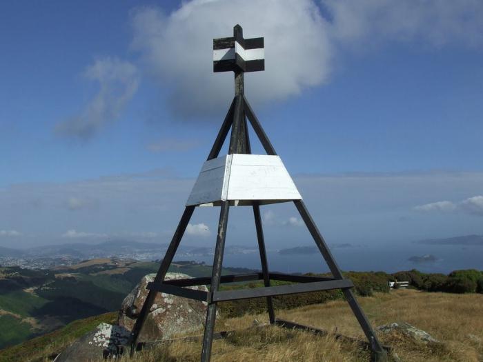
On the ground, the reference point is indicated by a pyramid-shaped structure made of stones, boards or metal tubes. Depending on the purpose, there are several types of benchmarks:
- Centuries are distributed according to a special scheme throughout the country. They are installed according to instructions at specified geographic locations. They are used mainly for scientific purposes.
- Fundamental ones are equipped along all leveling lines of the first class (between centuries) and along the most critical lines of the second class. The distance between points is from 50 to 80 km. They are laid exclusively in the ground in the form of reinforced concrete pillars and pylons. Since the fundamental benchmark can only be used in certain cases, an ordinary benchmark satellite with accurate transferred data is installed not far from it. It is used as a support for leveling classes 3 and 4.
- Ordinary benchmarks are wall, rock and soil. Fixed at a distance of 3.5 to 7 km from one another, these signs can be laid along all leveling lines.
The system of interconnected fundamental and ordinary reference points forms the GGS - the state geodetic network.
Cartographic designation of geodetic marks
On maps, the reference point is marked with special icons. They are distinguished as follows:
- for astronomical points;
- for GGS points;
- for central points fixed on the territory;
- for survey network points;
- for points of the state leveling geodetic network.
All these points are marked on the real surface of the Earth with metal pyramids or ordinary benchmarks. Geodetic centers indicating the location of a point are plotted on maps according to coordinates, that is, as accurately as possible, with indications of elevation marks.
What is a reference point? Elevations, mounds, hills or free-standing buildings with spiers, towers or bell towers included in the general geodetic network are designated by conventionally accepted combined icons. GGS points are indicated on large-scale maps, absolutely everything. Astronomical points that are landmarks are designated only in cases where they are starting points in a given area.
Triangulation (reference) points, their installation

The installation of permanent signs is carried out by the State Geodetic Leveling Network. The ground parts of the benchmarks are mutually visible to each other at a certain distance. The design and height of signs depend on the purpose, local conditions, soil and distances from one point to another.
Geodetic points can be made in the form of metal or wooden pyramids, stone or reinforced concrete pillars. The height of each structure depends on the location of the attachment. Any benchmark serves as a tripod or support for the measuring instrument and the observer.
The underground part of such a structure is made in the form of a foundation monolith filled with concrete. A mark cast from metal is embedded in the very point, which is the center of the point. The inscription on the latter indicates the number and type of this item. The name of the organization that performed the work and the year of installation are cast along with a mark (usually made of cast iron).
Construction and reference marks

Disc-shaped markers, made using cast iron, are installed in the walls industrial buildings, locks, abutments and This is done to monitor the static state of large structures. In addition to inscriptions, on disk marks there are protrusions intended for installation. The purpose of geodetic marks can be divided into the following categories:
- reference, or control, which are the basis for determining the position of established marks, taking into account safety and stability over time;
- auxiliary signs are intermediate signs for transmitting coordinates and values between deformation and reference marks;
- deformation marks, which are fixed directly on the walls of the observed structures or buildings (with spatial changes in the position of the object, these marks move with it).
Reference points in construction are a guarantee of timely detection of mobility or instability of a large object, such as a hydroelectric dam or a high-rise building.
Who needs all this?
Thanks to an interconnected system of designated points, a state geodetic network is formed. Special directories contain lists with the specified coordinates of all such points. This information is used by topographers to study the surface of the planet, in engineering and geodetic surveys, and for various needs of the country’s economy.

Lists indicating coordinate values are communicated to army officers along with topographic maps. Artillerymen also know well that a reference point is a mark indicating a known height, a kind of support for sighting on the ground.
The reference points on the Celsius temperature scale are considered to be the boiling and freezing values of water at sea level.
In business, this concept is used to describe a certain state of affairs when certain actions can lead to either complete failure or success.
Health, entrepreneurship
Since a reference point is a kind of reference point, a “hook,” this concept can be applied in many areas of human life.
Investigating the causes of frequent stress in people who constantly live in megacities, scientists found that the unnatural visual environment is to blame. The spread of right angles and lines, buildings of uniform color, a large number of static objects negatively affects emotional state person. A psychophysiological branch of science called visual ecology argues that the absence distinctive features architectural decorative elements overloads

The eye must highlight, fix some point, detail, element in visual space so that the brain perceives environment as comfortable, close to natural and harmonious. Only then does a person have a feeling of aesthetic and emotional satisfaction.
Reference points in business are a kind of airbags. They can be used to increase the competitive ability of an enterprise. If we take as a basis some marketing techniques or the state of affairs in the current period, we can identify comprehensive measures that need to be taken to change the situation for the better.
permafrost benchmark identification soil
Ground benchmarks types 160 op. sign and 162 op. the mark (Fig. 5, 6) in the area of seasonal freezing of soils, as a rule, is placed in drilled holes with a diameter of 50 cm. The soil benchmark consists of a reinforced concrete pylon in the shape of a parallelepiped with a cross section of 16x16 cm and a concrete slab (anchor) with a diameter of 48 cm, manufactured in advance. It is allowed to use square slabs measuring 50x50 cm.
A mark should be cemented into the upper edge of the pylon (Fig. 7). In the middle of the concrete slab, a recess measuring 20x20x15 cm is made, into which a reinforced concrete pylon is installed. The pylon can be replaced with an asbestos-cement pipe with an outer diameter of at least 16 cm, filled with concrete and reinforcement. A mark is inserted into the upper edge of the pipe.
When using an asbestos-cement pipe, to increase the connection of its base with the anchor, two mutually perpendicular rods 1.0-1.2 cm thick and 25 cm long are inserted at a distance of 7-10 cm from the base of the pipe.
When installing a pipe into the anchor hole, the ends of the rods are placed in the corners of the recess. In the southern zone of the area of seasonal soil freezing, concrete slabs (anchors) with a height of 20 cm are used, in the northern - 35 cm. The border between these zones runs along the line Valuyki-Rossosh-Kamyshin-Pallasovka.
It is allowed to lay benchmarks in wells with a diameter of 35 cm, but in this case the height of the concrete anchor in the southern zone should be 50 cm, in the northern - 80 cm.
The upper edge of the concrete slab (anchor) of the leveling benchmark of classes I, II, III and IV should be 30 cm below the depth of maximum soil freezing, regardless of the diameter of the well. For all benchmarks, the mark should be 50 cm below the surface of the earth. It is possible to manufacture an anchor by pouring liquid concrete into the well.
The depth of the well is the same as when laying benchmarks made in advance. In wells with a diameter of 50 cm, concrete is poured to 20 or 30 cm, respectively, and into wells with a diameter of 35 cm - 30 or 70 cm. concrete mortar insert a pylon or asbestos cement pipe. The length of the pylon or pipe should be such that the mark is at a distance of 50 cm from the ground surface.
It is possible to fill the wells with soil without waiting for the anchor concrete to set, provided that a layer of sand (loose soil) at least 10 cm thick is poured onto the liquid concrete.
It is allowed to replace reinforced concrete pylons with metal pipes with a diameter of 6 cm with a wall thickness of at least 0.3 cm or a piece of rail (Fig. 6).
In this case concrete slab(anchor) and pipe (rail) are fastened together at the place where the benchmark is made. The metal pipe should have four pins protruding 10 cm from it.
When laying benchmarks at the bottom of a well or pit, a layer of cement mortar at least 3 cm thick is poured under the base of the slab. It is prohibited to lay benchmarks in a pit (well) with soil loosened or sprinkled on the bottom.
Reinforced concrete benchmarks laid in aggressive soils are made of dense concrete.
In areas of moving sand, type 15 benchmarks are used (Fig. 8), which are screwed into the ground to a depth of at least 400 cm. The benchmark consists of a galvanized pipe, the upper end of which with a mark is placed 80 cm above the ground surface. A security plate is attached to the pipe. In this case, digging ditches is prohibited.
In wetlands, leveling lines are secured with soil tubular benchmarks, using pipes with a diameter of 6 cm with a wall thickness of at least 0.3 cm. A screw anchor with a diameter of at least 15 cm or a drilling spiral tip (auger, coil) with a diameter of at least 10 cm is welded to the lower end of the pipe cm and a length of at least 50 cm.
The pipe is screwed to such a depth that the screw anchor enters the underlying water-saturated layer of dense rock by at least 150 cm, but in all cases the depth of laying the benchmark should not be less than the depth of greatest freezing of the soil plus 100 cm. In the presence of shock-vibration mechanisms on In wetlands, you can lay benchmarks consisting of several drill rods or pipes screwed together with a diameter of 4-6 cm with a wall thickness of at least 0.3 cm.
A metal cone is welded to the lower end of such a reference point. The rods (pipe) are driven into the ground to such a depth that the cone enters the underlying water-saturated rock at least 300 cm. The upper end of the rod (pipe), to which the mark is welded, is placed 30 cm below the surface of the earth.
The moment of entry of a screw anchor (spiral tip or cone) into the dense underlying water-saturated rock layer is determined by a sharp slowdown in the rate of immersion of the anchor into the ground. They are building around the benchmark wooden frame 200x200 cm in size and 50 cm in height, filled with peat or mineral soil. A 100 cm long metal identification pole with a security plate is installed in the log house.
In the northern and middle zones of the permafrost region, tubular metal benchmarks of type 150 are placed in drilled or thawed wells (Fig. 9). Used as a reference metal pipes. The diameter of the pipe is 6 cm, the thickness of the pipe walls is at least 0.3 cm.
A mark is welded to the upper end of the pipe, and a multi-disc anchor is welded to the lower end, consisting of a metal disk and eight half-disks 0.5-0.6 cm thick and 15 cm in diameter.

For better screwing (pressing) of the pipe into the ground, the metal disk has blades.
The pipe is not filled with concrete.
An anti-corrosion and anti-frizz coating is applied to the outer surface of the pipe, and only an anti-corrosion coating is applied to the inner surface.
When the soil thawing depth is up to 125 cm, the base of the benchmark is located 200 cm below the thawing boundary.
If the thawing depth is 125 cm or more, then the base of the benchmark should be 300 cm below the thawing boundary.
If there are rocky inclusions in the soil that make drilling and thawing of wells difficult, tubular benchmarks type 165 op. the sign (Fig. 10) is laid in the pits.
Instead of a multi-disk anchor, a concrete anchor with a diameter of 48 cm and a height of 20 cm is made.
The base of the concrete anchor is placed 100 cm below the maximum thawing limit of the soil.
For all benchmarks in the area of permafrost soils, the upper end of the pipe with a welded mark is located at ground level.

In the southern zone of the permafrost region, the border runs along the line Vorkuta-Novy Port-Khantayka-Suntar-Olekminsk-Aldan-Ayan, only tubular benchmarks with concrete anchors are laid. If permafrost soils are not discovered during work, then the depth of laying the benchmark is increased by 50 cm and the upper end of the pipe with the mark is placed (due to this increase) 50 cm below the ground surface.
It is prohibited to use metal anchors instead of concrete anchors in the southern zone of the permafrost region.
A soil benchmark of type 9 op is laid into the rock, located on the surface or lying at a depth of up to 70 cm. sign (Fig. 11), which consists of a mark on cement mortar. A reinforced concrete or tubular identification pole with a security plate is installed 100 cm from the benchmark. The identification pillar is reinforced in the rock cement mortar, apply an anti-corrosion coating and paint. Around the identification pillar and above the benchmark, if it is on the earth’s surface, a tour of stones 50 cm high and up to 1 m in diameter is laid out. If the rock lies at a certain depth, the mark is covered with rock, and then the tour is laid out.
If the rock lies at a depth of more than 70 cm, then a benchmark type 176 op is used. sign (Fig. 11). A reinforced concrete pylon with a slab (anchor) is installed on the rock. The pylon is cast at such a height that its top edge is 50 cm below the surface of the earth. In the area of permafrost soils, it is allowed to lay a tubular benchmark with a concrete anchor instead of a reinforced concrete rock benchmark.

If there is a sheer cliff near the benchmark at a distance of up to 50 m, then on it oil paint bright colors draw a triangle with sides of 100 cm, inside which indicate the reference number and the initial letters of the organization that performed the work.

In the walls of artificial structures, buildings and vertical surface the rocks are laid by wall markers of type 143 (Fig. 12, 13).
When making wall benchmarks and marks (Fig. 7, 12, 13), the initial letters of the name of the organization that performed the leveling and the benchmark number are cast on the signs.
The wall benchmark shown in Fig. 12 is laid on the leveling lines of classes I and II, and the one shown in Fig. 13 is laid on the leveling lines of classes III and IV.
External design of benchmarks. The external design of the century-old benchmark consists of a reinforced concrete well with a protective cover and a lock; a mound made of stones; an indicator monolith and a fence made of four sections of rails (reinforced concrete pillars with a cross-section of 20x20 cm) with anchors laid to a depth of 140 cm and protruding 110 cm above the ground surface (Fig. 14).
It is allowed to use other external design, ensuring reliable preservation of the century-old benchmark.

The design of the fundamental benchmark in the area of seasonal soil freezing consists of a rectangular ditch (Fig. 15) and a reinforced concrete identification pillar (Fig. 16) with a protective plate (Fig. 17) with a thickness of at least 0.8 mm. The plate should be facing the reference point. A mound 30 cm high and 150 cm in diameter is made above the benchmark. The part of the identification pole protruding above the ground is painted with brightly colored oil paint. The cross-section of the ditch along the lower base is 20 cm, along the top - 120 cm, depth - 70 cm. The name of the organization and the reference number are signed on the identification pole with black paint (for example, Roscartography, 1274). A mound of stones 150x150 cm, 70 cm high, is laid above the rocky foundation marker.
The base of the identification pillar is cemented with the rock or in the rock.
In the area of permafrost soils, the external design of fundamental benchmarks is the same as that of ground benchmarks, but in forested areas a tubular metal identification pole is placed (Fig. 9 and 10), and within a radius of 100-150 m from the benchmark on trees at a height of 150-250 cm make ten marks with bright paint, which should look towards the benchmark. The external design of the ground benchmark (Fig. 18) is a ditch and an identification pole in the form of a reinforced concrete pylon with a slab (anchor), installed 80 cm from the benchmark. In forested areas, wooden identification poles are permitted.
The size of the lower base of the ditch is 20 cm, the upper - 120 cm, depth - 50 cm, length - 1280 cm. A mound 30 cm high with a diameter of 100 cm is poured above the benchmark. The length of the pylon, which has bevels on two sides in the upper part, is 140 cm, and the transverse cross-section 16x16 cm. Slab diameter 48 cm, thickness 15 cm (Fig. 16).

The connection between the pylon and the slab is the same as for the benchmark. The base of the slab is located 80 cm below the ground surface. When using an anchor with a diameter of 34 cm, its height is increased to 25 cm, and the laying depth is up to 90 cm. A security plate is securely attached to the identification post (when casting the pylon) (Fig. 17). The inscription on the plate is cast, stamped or applied by punching.
When installing an identification pole, the security plate must face the reference point.
The part of the identification pole protruding above the ground surface is painted with oil paint of bright colors (red, orange, yellow). The marker number and the name of the organization that founded it are indicated in black paint on the pole. The identification pole may be tubular. A metal plate is welded to the top of the pipe, to which a security plate is bolted. Pipe on top anti-corrosion coating paint within the protruding part with brightly colored oil paint.
On the reverse side of the plate is written in black paint the number of the benchmark and the initial letters of the organization that founded it. A plug is welded to the upper end of the pipe.
The lower end of the pipe must have a concrete (metal) anchor with a diameter of 48 cm and a thickness of 15 (0.5) cm, buried 100 cm into the ground. When using an anchor with a diameter of 34 cm, its height is increased to 25 cm, and the laying depth to 90 cm. The top of the tubular identification pole should be located 100 cm above the ground surface.
In forested areas of permafrost, as well as in wetlands of seasonal soil freezing, a log frame with dimensions of 200x200 cm and a height of 50 cm is built above the ground benchmark (Fig. 19).

The log house is filled with soil and moss, which is taken no closer than 15 m from the benchmark. In the log house above the benchmark they install wooden post 70 cm long, and next to it there is a metal identification pole; within a radius of 100-150 m from the benchmark, ten marks are made with bright paint on trees at a height of 150-250 cm.
In the tundra above the benchmark, a mound measuring 200x200 cm and 50 cm high is built from earth and moss. The mound is covered with a layer of turf. A wooden pole 70 cm long is installed above the benchmark, and an identification pole next to it. Earth, moss and turf are taken no closer than 15 m from the benchmark.
In the area of permafrost, depending on how the benchmark is laid, by drilling (thawing) or in a pit, identification metal pole installed at a distance of 100 or 70 cm from the benchmark (Fig. 9, 10). The lower end of the pipe must have an anchor, which is buried into the permafrost soil by at least 50 cm. The upper part of the identification mark is placed 100 cm above the ground surface and painted with oil paint of bright colors. Various mechanisms can be used for digging pits, drilling wells, driving piles and screwing pipes (Appendix 8). Documentation drawn up upon completion of work on laying benchmarks:
- · report with explanatory note; benchmark bookmarking magazines;
- · a list of established benchmarks and a diagram of their location (on the largest scale map);
- · acts of submitting benchmarks for safety supervision;
- · photographs of buildings and rocks in which wall markers are embedded;
- · maps at a scale of 1:25000 and larger, aerial photographs showing the locations of established and surveyed benchmarks, outlines. The scale of the outline is chosen so that the nearest landmarks indicated in the description of the location of the benchmark fit on it. Outlines are drawn up by eye, based on maps, aerial photographs in ordinary conventional topographical signs, horizontal lines on them are drawn conventionally, only to show the nature of the relief.
A separate document provides determination schemes and observation materials for the instrumental determination of the coordinates of fundamental, secular and ordinary benchmarks and a list of coordinates of benchmarks along leveling lines.
The coordinates of secular and fundamental benchmarks determined by instrumental methods are given with an error of no more than 1.0 m, ordinary benchmarks and marks with an error of no more than 10 m.
Benchmark (geodesy)
| This page or section is believed to be infringing.
Its contents were probably copied with virtually no changes. |
Rapper in France
rapper(fr. repère sign, starting point) V geodesy- a sign fixing a point on the earth’s surface, the height of which relative to the original level surface is determined by leveling. In the Russian Federation, the heights of benchmarks are calculated relative to the zero of the Kronstadt foot rod. Benchmarks are divided into fundamental and ground.
Fundamental benchmarks, which are reinforced concrete pylons, are laid in the ground every 50-80 km on all leveling lines of the 1st class, as well as on the most critical lines of the 2nd class and near the most important offshore water-measuring installations. Ordinary benchmarks laid every 5-7 km on leveling lines of all classes are divided into ground ones, installed in the ground; wall, laid in the walls of permanent structures; rocky, laid in rocky soil. Secular benchmarks are laid at the intersection points of class 1 leveling lines.
Fundamental and ground benchmarks, located on the territory of the country, form a state leveling network. Benchmarks of the state leveling network serve as starting points (reference points) for determining the heights of intermediate points on the earth's surface during topographic surveys and various types of survey work, and are also used for scientific purposes in studying differences in sea levels.
In Russia, the Baltic height system is used in the Far East. At the end of the 1980s, the mark of the Kronstadt footpole was transmitted to the coast of the Far Eastern seas; the expected error was approximately 1 meter.
Brand
- Brand- point of the leveling network, which serves to secure a point whose height above sea level is determined by leveling. The stamp is a cast metal disk, 8 to 10 centimeters in diameter, mounted into the wall of a permanent (usually stone) building or bridge. In the center of the disk there is a hole with a diameter of about 2 mm, which determines the position of the mark. The stamp is stamped with its number, as well as the name of the organization that carried out the leveling work. Unlike a benchmark, a mark can be deformable. A mark attached to a part of a structure's structure (foundation, column, wall) for the purpose of measuring settlement, roll or shear of the foundation.
See also
Notes
Links
Wikimedia Foundation. 2010.
See what “Reper (geodesy)” is in other dictionaries:
- (French repère “sign, starting point”) Benchmark (geodesy) Benchmark (geometry) Benchmark (physics) Benchmark (artillery) See also Rapper rap performer ... Wikipedia
Reper (French repére sign, starting point) Reper (geodesy) In mathematics Reper (differential geometry) Reper (affine geometry) See also Rapper rap performer ... Wikipedia
Ground benchmark- – a leveling benchmark, the base of which is installed below the depth of freezing, thawing or soil movement, serving as a high-altitude geodetic basis for the creation (development) of geodetic networks. [SP 11 104 97] Category... ...
Benchmark wall- – leveling benchmark installed on load-bearing structures capital buildings and structures. [SP 11 104 97] Term heading: Geodesy tools Encyclopedia headings: Abrasive equipment, Abrasives, Roads... Encyclopedia of terms, definitions and explanations of building materials
Leveling benchmark- – geodetic sign defining a point in the leveling network. [RTM 68 13 99] Term heading: Geodesy tools Encyclopedia headings: Abrasive equipment, Abrasives, Roads... Encyclopedia of terms, definitions and explanations of building materials
Benchmark (French repère - mark, sign, starting point) in geodesy, a sign that fixes a point on the earth's surface, the height of which relative to the original level surface is determined by leveling. In the USSR, R. heights are calculated... ...
- (Greek geōdaisía, from gē Earth and dáiō I divide, divide) the science of determining the shape, size and gravitational field of the Earth and of measurements on the earth’s surface to display it on plans and maps, as well as to carry out various... ... Big Soviet encyclopedia
geodesy- ▲ applied science regarding, determine (implicit), position, material body geodesy the science of determining the spatial position of objects. triangulation. polygonometry. mine surveying department. surveyor. surveyor's gravimetry. |… … Ideographic Dictionary of the Russian Language
I Benchmark (French repère mark, sign, starting point) in geodesy, a sign that fixes a point on the earth’s surface, the height of which relative to the original level surface (See Level surface) is determined by leveling (See... ... Great Soviet Encyclopedia
- (French geröge sign, starting point) 1) R. in geodesy, geodesy, a sign fixing a point on a leveling network. Depending on the location where the river is laid, it can be wall or ground. 2) R. in mathematics in space (on a plane) a set of three (two) vectors with ... ... Big Encyclopedic Polytechnic Dictionary