We will send the material to you by e-mail
All components of the station autonomous water supply must work in harmony. In this case, the efficiency provided by the equipment manufacturer will be ensured. Correct installation and the setting for the hydraulic accumulator will also reduce negative impacts for technology. This will allow you to extend its service life without additional costs. Your own knowledge and skills will help you personally perform work operations, without resorting to the services of specialized service companies.
Design of the device for the hydraulic accumulator
To better understand the functions of individual elements, it is necessary to consider the system as a whole.
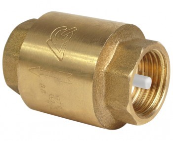
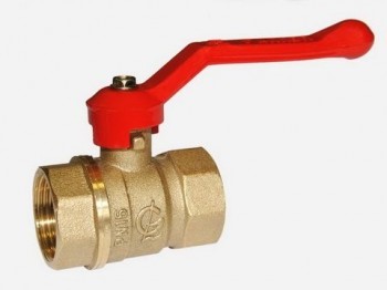
From a well or other source, water is pumped into the main pipeline. To prevent its movement in the opposite direction, it is installed safety valve. Installed in the right places shut-off valves. It is used for preventive maintenance, adjustments, and replacement of failed units.
Water flows through the pipeline into a special container, which performs several functions:
- accumulation and storage of liquid reserves;
- creation of normal pressure in sections of the pipeline connected to consumers;
- damping of pressure drops when connecting local water supply to centralized networks.

The main working element of such a container is a flexible partition. But the initial pressure in the tank itself is created by the pump. With appropriate equipment, it is controlled from a special remote control. Data is received there from the pressure switch for the hydraulic accumulator.
Above is part of the class diagram " smart home" She connects to common system management. In practice, more economical solutions are often used.
To successfully solve the indicated problems, the following designs of hydraulic accumulators are used:
- A durable tank is created with elements that are useful for strong fastening on a horizontal or vertical plane.
- Metal cases are protected from corrosion by special coatings. They are designed for pressures up to 6 atm. and higher.
- A rubber membrane is inserted inside.

- For adjustments and adding and releasing air, a built-in spool is used. A special valve is installed in large containers.
- To improve consumer characteristics, a layer of enamel, ceramics and other chemically neutral compounds is created inside the tank. For systems with drinking water They use completely safe types of rubber.
Pay attention! If you purchase a hydraulic accumulator for a heating system, you need to pay attention to the suitability of the model for working with liquids at elevated temperatures.

This picture shows another important element, flow filter It prevents the entry of mechanical contaminants, damage to the relay and blocking of its drive mechanisms. The increased tank capacity is useful not only for high daily consumption. It will reduce the number of pump starts/stops, which will have a positive impact on the durability and reliability of the system.
The standard method for calculating tank volume (VT) uses the following formula:
OB=16.5 x RV/KV x KD x 1/DVK, Where:
- RV– consumption in liters per minute. They use the sum of all needs, household, cooking, sanitary and hygienic and others.
- HF– number of starts of the injection pump in 60 minutes. It is recommended to select the parameters in such a way that the number of such starts does not exceed 8-10 over the corresponding period of time at maximum consumption.
- KD– complex pressure coefficient. It is calculated using the formula Dvk x Dvyk/(Dvk – Dvyk). Here Dvk and Dvyk are the maximum and minimum pressure levels at which the pump is turned on and off.
- DCK- this is the pressure that is formed in the part of the tank where the air damper is located.
In order not to embarrass yourself when year-round accommodation For a family of three, a tank with a capacity of 40-60 liters is enough. Similar advice is given by specialized experts. In fact, it is better to make a more accurate calculation using the above method. The results obtained should be increased taking into account guest visits and other situations accompanied by increased water consumption. This approach will help you purchase a hydraulic accumulator for water supply, the price of which will correspond technical specifications and the needs of future users.
When placing the tank at the highest point of the structure, the force of gravity will be used. But we must take into account that the room must be reliably protected from adverse external influences. It supports all year round temperature above 0°C.

It is necessary to remember about the increase in mechanical loads. A large water tank weighs a lot, so sometimes additional reinforcement of the structure’s load-bearing frame is required. For these reasons, large containers are often installed in the basement.

Related article:
How to install a pressure switch for a hydraulic accumulator
Before performing work operations, it is necessary to clarify general requirements. To function in optimal mode the pressure difference for turning the pump on and off is set within the range from 0.9 to 1.8 atm. Exceeding it will increase energy consumption.
To calculate what pressure should be in the hydraulic accumulator (HHA), use the formula DGA = (B+6.5)/10, Where:
- IN- height. This distance is taken from the central axis of the tank to the highest point at which water is drawn.
- 6,5 – this digital coefficient takes into account the height of a particular building. Taken as an example typical cottage(2 floors).

Pay attention! If standard equipment is not available, you will need an appropriate measuring device.
The process of connecting a pressure switch to a hydraulic accumulator
For study, this article discusses a mechanical pressure switch for a hydraulic accumulator. This design is repeated in modifications by different manufacturers, with relatively minor changes.

This product is connected to the water supply system in assembled form. Can be used for placement in a convenient location flexible tubes, designed for appropriate pressure levels. If necessary, use transition fittings. Upon completion of installation, the tightness of the threaded connections is checked experimentally.

The electrical connection can be made directly to the pump power supply circuit. Use wires designed for appropriate power. To eliminate errors, it is recommended to use products with color braiding. The “earth” standard is a combination of yellow and green. The electric motor is connected to a 220 V network through an automatic device, which ensures quick shutdown in the event of a short circuit.

All electrical installation work is carried out with the voltage turned off. It is necessary to exclude accidental supply of voltage during the process of adjusting the pressure switch for the hydraulic accumulator.

Connection diagram when using a dry-running sensor
Setting the accumulator pressure switch
Use the following algorithm:
- Turn off the pump and drain the water.
- Turn on the equipment and increase the pressure, followed by draining the liquid. Record the motor on/off levels.
- Increase the threshold at which voltage is supplied to the engine using a nut on a large spring (clamp it).

The water supply system of a private house simply must be reliable and provide the house with water uninterruptedly under any circumstances. climatic conditions. With grief half and half it turns out centralized system water supply and where it is possible to connect to it, private owners are provided with water all year round. In cases where this is not possible, you have to build a water supply system with your own hands, and the connection diagram of the system elements depends on a lot of factors.
Purpose of a modern hydraulic accumulator
The durability, efficiency and uninterrupted operation of the water supply system depend entirely on the connection diagram. One of the main elements of the system is the hydraulic accumulator. The performance of the entire complex will depend on the correct choice of its wiring diagram. - promote stability of water supply, stability of water pressure in the system and provision of the necessary reserve volume of water, depending on the model and type of device.
In principle, all hydraulic accumulators are designed in the same way. Their work is based on the interaction of compressed air and water. Compressed air exerts pressure on the mass of water through a rubber membrane, thereby maintaining the required level in the entire system. This can be useful when there are power outages or temporary inoperability of the water pump, when the pressure in the system is unstable.
Types and brands of hydraulic accumulators
The connection diagram for a hydraulic accumulator for water supply systems directly depends on the type of hydraulic accumulator, so we simply must consider them at least schematically. Despite the almost identical principle of operation, all hydraulic accumulators may have some design features that directly affect their physical location and, as a result, the connection diagram:

But the type of location of the hydraulic accumulator directly depends on the type of pump supplying water. Thus, horizontal models are mainly used for remote, external pumps, and vertical hydraulic accumulators work in tandem with submersible ones. Of the domestic manufacturers of hydraulic accumulators, the most popular, but not the highest quality, hydraulic accumulators are considered to be Gilex, and among European brands - Reflex and Tsilmet.
Hydraulic accumulator functions
It is also necessary to touch upon the main ones in more detail, then the connection diagrams and the need for each of them will be much clearer.
- Stabilization of pressure in the water supply system. The pressure is created by the pump, and the hydraulic accumulator plays the role of a capacitor in electrical circuit. It accumulates water, but releases it strictly under the specified pressure, regardless of what pressure the hydraulic pump creates and what type it is. This extends the life of an expensive pump because it does not have to turn on and off every time the user opens the tap.
- Accumulation, accumulation of a minimum supply of water in case of interruptions in energy supplies. Depending on the model of the hydraulic accumulator, it can accumulate a certain amount of water and operate for some time in autonomous mode, without the participation of a pump. The minimum volume of an emergency hydraulic accumulator is 100-120 liters.
- Advance and damping of hydraulic shock. Very useful feature hydraulic accumulator. The fact is that with a relatively unstable voltage in the network, a situation may arise when the pump electric motor sharply increases the pressure in the system, which can lead to failure household appliances, connected to and heating. The hydraulic accumulator eliminates pressure surges and water hammer.
Connection diagram of the hydraulic accumulator to the pumps
Depending on the type of pump, as we said earlier, the connection diagrams for the hydraulic accumulator to the pumps may be different. Let's briefly look at the main ones.
- Connection diagram deep well pump and hydraulic accumulator involves installing a hydraulic accumulator after the pump. In this case, it will be necessary to install a check valve so that water under the pressure created in the device is not pushed back into the well. The volume of the accumulator is calculated based on the level of water consumption. The average number of pump starts according to the passport is about 10, therefore, based on these data, a hydraulic accumulator of the appropriate volume is selected.

- A surface pump with a hydraulic accumulator is connected slightly differently. Exactly the opposite. The water sucked in by the pump first passes through a storage tank, after which it is supplied to the consumer. This connection diagram allows you to adjust the lower pressure threshold and the upper one. To know them, in each specific case you need to start from the average pressure of the system, which is dictated by the devices and the number of consumption points. In this circuit, it is necessary to take into account the connection diagram of the hydraulic accumulator pressure switch, on which the boundary parameters are set.

- In addition to these diagrams, there are also diagrams for connecting a hydraulic accumulator as part of pumping station, with a booster pump, as well as a connection diagram for the heating system. They differ slightly, mainly in the presence additional elements, such as expansion tank, additional electronic valves and regulators.

Knowing these schemes, at least in general outline, you can provide your home with water all year round and stably high level. The main thing is to choose the right hydraulic accumulator.
The most important element of the pumping station is the hydraulic accumulator.
The scheme for connecting it to the well depends on the degree of autonomy of the water supply and the absence or presence of a water heater in the water supply network.
Let's consider possible options installations, as well as the design and types of hydraulic accumulators.
 In the very simple design A hydraulic accumulator (HA) is a container installed at a certain height (above any of the consumers) and equipped with level sensors.
An example of such a device is a water tower that supplies the water supply network in a rural locality.
In autonomous water supply systems of private houses, such a HA is usually installed in the attic.
The pressure in the taps is provided by the weight of the liquid column; level sensors or a float switch control the operation of the pump.
Modern pumping stations use more advanced hydraulic pumps, which can be installed at any level - even below water intake points. The volume of such a device is divided into two parts: water from the water supply is pumped into one, the other contains air with some overpressure(pumped by a pump through a regular spool).
Both parts are separated by an elastic element, so when one of them is filled with water, the volume of the second decreases, and accordingly the pressure of the air in it increases. It is the air pressure that performs in such a hydraulic system the same function as gravity in a water tower - it provides pressure in the system.
Structurally, GAs are divided into two types:
- Membrane: the volumes for water and air in such tanks are separated by a rubber membrane. There are membrane tanks designed for use in closed systems heating. They are designed for lower pressure than HA for water supply, and they use technical rubber, not food grade rubber. To avoid confusion, it is customary to paint HA for heating red, and for water supply - blue.
- Cylinder: a rubber bag with a flange is inserted inside such a storage device, which is connected to the water supply. Thus, in balloon HAs, water does not come into contact with the metal walls of the housing at all. In addition, replacing the cylinder is not difficult and can be easily done by the user, while in some models you have to contact a service center to replace the membrane.
The volume of HA can vary greatly - from 24 to 1000 liters or more. It should be taken into account that the passport shows the total volume of the tank including the air chamber.
As for the volume of water that the tank can hold, it will depend on the settings of the pressure switch for the amount of air pumped in.
So, with relay settings of 1 atm/2 atm (on/off pressure) and an air pressure of 0.8 atm (checked with an empty cylinder), 30 liters of water will fit in a 100-liter GA.
If the shutdown pressure is raised to 2.5 atm, the storage capacity will increase to 38.5 liters.
In HAs with a volume of over 100 liters, a valve is installed in the upper part of the water chamber to release air, which is released from the liquid during operation and gradually accumulates. Tanks with a smaller volume do not have such a valve and must be emptied periodically to get rid of accumulated air.
GA can have horizontal and vertical design. The device and operating principle of both varieties are completely identical; the choice of one or another model depends solely on the ease of installation.
 The hydraulic accumulator has an extremely simple device; you can also connect it yourself. - Recommendations for selection and installation, read carefully.
Place in the water supply system
 If the operation of the domestic water supply was provided by only one pump, it would have to be turned on every time as soon as one of the users opened the tap.
Such a mode would lead to the rapid exhaustion of the electric motor's life, since the starting moment is the most difficult for it.
The pump passport even indicates such a parameter as the maximum permissible switching frequency.
Even for the most durable electric motors, it is no more than 15 starts per hour, for all others - 10 or less.
This is what determines the use of GA. It accumulates not only water, but also the pressure necessary for comfortable use of the water supply. At the same time, the operating mode of the pump looks completely different: it runs longer, but - most importantly - turns on less often.
At the same time, the membrane or balloon storage device performs another important function: it acts as a damper, smoothing out water hammer.
However, HA is not always needed in water supply systems. Here are the cases in which you can do without it:
- If water is used in long cycles: typical example- watering the garden. Here GA is not only not needed, it is contraindicated. The water supply in it will be used up very quickly and the pump will have to be turned on frequently to replenish it. In the absence of a HA, the unit will operate quietly in a stable mode.
- If the pump is equipped with the latest automation, which provides the function of smoothly starting the engine and regulating its power depending on the pressure in the system.
Connection diagram for a hydraulic accumulator for water supply systems
The method of connecting the HA will depend on the features and purpose of the pumping station. Let's consider three options.
Option 1
 The pump supplies water from a well, borehole or storage tank, while only cold water supply is provided.
In this case, the HA is installed inside the house in any convenient place.
Typically, it, a pressure switch and a pressure gauge are connected using a five-pin fitting - a piece of pipe with three taps that cuts into the water supply.
To protect the HA from vibrations, it is connected to the fitting with a flexible adapter. To check the pressure in air chamber, as well as to remove air accumulated in the water chamber, the HA must be periodically emptied. Water can be drained through any water tap, but for convenience, the drain valve can be cut through a tee into the supply pipeline somewhere near the tank.
Option 2
The house is connected to a centralized water supply, and a pumping station is used to increase the pressure. With this method of application, the HA stations are connected in front of the pump.
IN in this case it is designed to compensate for the decrease in pressure in the external line when the electric motor starts. With this connection scheme, the volume of the HA is determined by the power of the pump and the magnitude of pressure surges in the external network.

Installation of a hydraulic accumulator - diagram
Option 3
Connected to water supply storage water heater. The HA should be connected to the boiler. In this embodiment, it can be used to compensate for the increase in water volume in the heater due to thermal expansion.
Diagram for connecting a hydraulic accumulator to a submersible pump
If the pressure characteristic of a submersible pump allows maintaining acceptable pressure at water points in combination with sufficient performance, the HA is connected according to the usual scheme using a five-terminal or three-terminal fitting.
However, wells can be very deep, and their dimensions often do not allow the installation of a pump of sufficient power (for example, 3-inch wells).

Connecting a hydraulic accumulator with your own hands
In such cases, the following scheme is used:
- Installed in the well submersible unit, the power of which is only enough to lift water to the surface.
- Near the well, on the surface or in the ground, a HA is installed in the form of a simple container equipped with level sensors. These sensors control the operation of the submersible pump.
- A self-priming pump is installed near the storage tank (if it is buried in the ground) or normal suction (if the HA is installed on the surface), which supplies water directly to the home water supply. In this case, a membrane or balloon HA is installed in the house, and the pump is controlled by a pressure switch.
Electrical diagram for connecting the pressure switch to the hydraulic accumulator
Typically, pressure switches for household pumping stations have two groups of contacts, but sometimes you come across models with one.Each group consists of two pairs, and both pairs are closed or opened simultaneously. The contacts in each pair are labeled, for example, “Line/Load” or “Line/Motor”.
In principle, it is not necessary to follow these notations. You can even, for example, connect wires from the network to the “Line” contact of one pair and the “Load” contact of the other.
The main thing is that both wires are not connected to the contacts of one pair - this will lead to short circuit. The wires leading to the pump motor should be connected to the remaining two contacts. It is desirable that the colors of the braids of the cores connected to one pair match. Before you connect network wire, make sure it is not plugged into a power outlet.
To connect the grounding conductor (usually it has a yellow-green braid) there is a screw on the relay body, marked with the corresponding symbol.
When connecting the wire from the relay to the pump motor, the blue-braided wire should be connected to the “zero” contact, and the red or black wire to the “phase” contact.
Often, for reliability, the grounding contacts of the pump and the relay are connected to each other, but this is not necessary.

Pressure switch in a water supply system with a deep pump
The cross-sectional area of the wire cores must correspond to the power of the electric motor. For copper wire The cross section is selected based on 1 sq. mm for every 8 A of current. To determine the current strength in a single-phase network, it is necessary to divide the power of the electric motor by 220. So, for example, in the circuit of an electric motor with a power of 1.5 kW, a current of 1500/220 = 6.8 A will flow.
It is important not to confuse the diameter of the wire core and its cross-sectional area, since these values can be comparable. For example, the cross-sectional area of a core with a diameter of 1.5 mm is 1.76 square meters. mm.
Please note that the electrical connection must be made only after connecting the pressure switch to the water supply.
 Nowadays, the lack of centralized water supply is no longer such a problem. big problem. Great variety pumping equipment allows you to arrange autonomous system water supply without much difficulty. , installation and repair, read on.
You will find a water supply diagram for a private house with a storage tank in the topic.
Video on the topic
If supply country house Since water is supplied from a well or well, and not from a centralized system, in most cases water supply schemes with a hydraulic accumulator are used. This allows you to ensure uninterrupted supply, good pressure in the network and extend the service life of pumping equipment.
This article will describe in detail the advantages of using a hydraulic accumulator and options for connecting it to the system. As well as options for laying in-house pipes.
Why do you need a hydraulic accumulator?
Both the well and the well may have insufficient flow (see). In other words, they are not always able to dispense as much water as you need at one time. Sometimes this problem does not arise immediately, but after several years of operation of the source.
It is logical that in this case there should be a supply of water in the house. But not in buckets and cans, but in the system itself. And this can really be achieved if you include a hydraulic accumulator or storage tank in the water supply scheme.
Advantages of a hydraulic accumulator
A storage tank is, as they say, “ last century" It is inconvenient and not practical.
Judge for yourself:
- It must be installed above water consuming rooms, that is, in the attic. This means that it needs insulation, otherwise the water will freeze in winter.
- Nobody cancels the risk of leaks and tank overfilling. It's rare, but it happens. The consequences are easy to imagine.
- Water from storage tank enters the devices under pressure of its own weight. And this is not enough for the normal operation of plumbing fixtures and especially household appliances– washing machine and dishwasher.

This leads to an obvious conclusion: it makes sense to include storage capacity in the system only in small houses for summer use, not equipped modern devices. If you live in a house permanently, a water supply scheme from a hydraulic accumulator is more suitable for you.
And here's why:
- This is a more advanced device - it allows you to adjust the pressure in the system according to your needs;
- The hydraulic tank should also be in a warm room, but this problem is easier to solve, since it does not need to be raised to the highest point. The basement of the house and any technical room are suitable for installation;
- Accordingly, possible leaks are not so terrible: water will not wet the ceilings or damage repairs and furniture.

How does it work
The hydraulic accumulator is a sealed container, internally divided into two sections. A rubber diaphragm or a hollow “bulb” can act as a separator.
Water enters one section, and the other contains air, which, as the first section fills, is compressed, creating pressure on the diaphragm.

As the tank empties when dispensing water, the air pressure drops. When it reaches the minimum limit value, the pressure switch is activated, which starts the pump. He pumps water into the tank again until the pressure reaches maximum.

As a result:
- We have a constant pressure in the system;
- The pump does not turn on every time the tap is turned, so its parts wear out less and last longer;
- The water supply scheme with a hydraulic accumulator allows you to always have a supply of water in case of large amounts of water and the inability of the source to produce the required volume at a time.
The volume of the tank is selected based on the needs of the family. It can be either 5 or 500 liters.
What does the system consist of?
Now let's trace the entire path of water from the well/borehole to the tap farthest from the source.
We bring water into the house
So, we have a water source not far from our house. From there it is laid underground into the house water pipe. It must lie below the freezing level of the soil or be laid together with the heating cable.
This is important. When choosing a place for a well, make sure that the septic tank at the dacha outdoor toilet and other objects that pollute groundwater, were at least 30 meters away from him.

The pipe from the source is connected to the pumping station. Or, if there is a hole in the well, to a hydraulic accumulator. Always installed in front of the pump check valve so that the water from it does not flow back to the source.
If water is needed not only in the house, but also in the yard, after the hydraulic accumulator, a tee with a tap is installed on the pipe coming out of it. The home pipe leads to a water purification system, at the outlet of which a tee is again installed, separating the flows into cold and future hot water.
Now let’s learn more about how to properly connect a hydraulic accumulator with your own hands. It can be stand-alone or part of a pumping station, depending on whether you are using a submersible or surface pump.

Even with explanations to the picture, it is quite difficult to understand what the assembly consists of and what the purpose of each fitting is.
Let's explain:
| Fitting | Connection sequence |
|
|
The first is an adapter from a hose to a diameter of 32 mm. |
|
|
Next, a tee with a tap is screwed onto it, allowing you to drain water to repair the system. |
|
|
This element is necessary if it is necessary to turn the pipe to the station. |
|
|
The coarse filter traps sand and small stones, preventing them from entering the system. Without it, all subsequent elements can quickly fail. |
|
|
In the case of submersible pump The check valve is installed on the suction pipe. If you are using a pumping station with surface pump, then its place is immediately behind the filter. |
|
|
This connecting element allows you to make the unit dismountable for quick replacement of any failed fitting. |
|
|
Locking ball valve can be installed anywhere. It is used to turn the water supply on or off. |


- If a pumping station is used, all that remains is to connect the assembled unit to it, since a pressure gauge and pressure switch come with it.
- If the pump is located in a well, then the next step is to connect a five-pin fitting through an American one. The diagram below shows what each pin does.

A fine filter or water treatment station is “placed” on the pipe leading to the hydraulic accumulator.

Advice. Before purchasing equipment and assembling it, have your water tested to see what kind of treatment it needs.
Now you can do the internal wiring.
Internal wiring
To supply water to all “consumers”, you need to buy pipes and all kinds of connecting elements. How many of them will be needed? A diagram indicating all elements of the system with distances marked on it will help answer this question.

But first you need to decide which connection method to use.
- Serial connection is easier and cheaper. But with such a connection simultaneous switching on several taps, the pressure at the furthest point from the accumulator will be low.
- A collector connection involves connecting a separate line to each device. They all come out of a common manifold installed at the input. This scheme ensures equal pressure at all points of water consumption. But the cost of plumbing will be significantly higher.

The first method is only suitable for houses with a small number of consumers and a short length of water supply. The second is more practical and effective if we are talking about a private house in which a large family lives and all the necessary equipment is installed.
- After the tee, dividing the total flow into cold and hot branches, into the pipeline cold water a collector is installed with the right amount conclusions. Each of them must have a shut-off valve.

- The second pipe after the tee is connected to the inlet pipe of the water heater.

- The pipe leaving the water heater is also equipped with a manifold, from which the lines diverge to individual consumers.

If you think through everything in advance and do the work carefully, the entire unit for pumping, cleaning, heating and distributing water can fit in a small area - in a corner of the room, a closet or a niche.
The following illustrations will help you better imagine how the different stages of work are performed:
Advice. To reduce pressure loss, try to make fewer turns and angles. For example, you can lay lines under the floor in a straight line from the collector to the water distribution device.
Conclusion
Schemes of water supply systems with a hydraulic accumulator will provide no less comfort in a private house than in an apartment with a centralized supply. If you know and understand the operating principle of the system, you can assemble it yourself. If you have everything necessary tools, it's not much more complicated than assembling a constructor.
For more information and the opportunity to see the process of connecting the most important nodes with your own eyes, watch the video in this article.
The pressure switch for the hydraulic accumulator is fully responsible for its operating mode and the frequency of activation of the pump. This is the main control device of the system. The entire water supply scheme is closely related to the values set on it. It is this element that gives the signal to the electric pump to turn on or off.
Place of the device in the water supply system
(GA) consists of a container, a valve for bleeding, a flange, a 5-pin fitting (tee) with couplings for connection, as well as a pressure switch (control unit), which sets the rhythm of all work.
- main control element
- ensures work without overloads
- controls optimal filling of the tank with water
- extends the service life of the membrane and all equipment in general
A pressure gauge that shows the pressure in the tank is included in the kit or can be purchased separately.

The pump pumps water out of the well and directs it through pipes. Next, it enters the GA, and from it into the home pipeline. Task membrane tank– maintain stable pressure, as well as the pump operating cycle. There is a certain maximum activation for it - about 30 per hour. When exceeded, the mechanism experiences loads and through short time may fail. The water pressure switch must be adjusted so that the devices operate as expected, without exceeding the critical load.
Setting up a storage tank means creating the required number of atmospheres in it and correctly setting the pump response thresholds
Design and principle of operation
The device looks like a box of various shapes with controls under the lid. It is attached to one of the outlets of the fitting (tee) of the container. The mechanism is equipped with small springs that are adjusted by turning the nuts.
Operating principle in order:
- The springs are connected to a membrane that responds to pressure surges. An increase in indicators compresses the spiral, a decrease leads to stretching.
- The contact group reacts to these actions by closing or opening the contacts, thereby transmitting a signal to the pump. The connection diagram necessarily takes into account the connections of its electrical cable to the device.
- The storage space fills up and the pressure increases. The spring transmits the pressure force, the device operates according to the set values and turns off the pump, sending it a command to do so.
- The liquid is consumed - the pressure weakens. This is fixed, the engine turns on.

The assembly consists of the following parts: a housing (plastic or metal), a membrane with a cover, a brass piston, threaded studs, metal plates, cable sleeves, terminal blocks, a hinged platform, sensitive springs, and a contact assembly.
The operating algorithm of the control device is as simple as possible. The mechanism responds to changes in the number of atmospheres inside the drive. The moving platform is raised or lowered by springs depending on the pressure on the piston, which in turn interacts with contacts that signal the pump to start or stop pumping.
Installation
Often the HA kit is sold disassembled, and the control unit must be installed yourself.
Connecting the pressure switch to the hydraulic accumulator looks like this in stages:
- The station is disconnected from the network. If water has already been pumped into the storage tank, it is drained.
- The device is fixed permanently. It is screwed onto the 5-pin fitting of the unit or onto the outlet pipe and must be firmly fixed.
- The wiring diagram is normal: there are contacts for the network, pump, and grounding. The cables are passed through holes on the housing and connected to contact blocks with terminals.

Electrical connection to the pump
Settings
Before adjusting the relay, you need to take into account that its values are inextricably linked with the pressure inside the membrane tank. First you need to create the required amount of pressure inside it, and then move on to working with the control in question.
The adjustment is carried out in 3 stages:
- pressure inside HA
- pump start level
- shutdown mark
For optimal performance it is necessary to adjust the parameters several times empirically, taking into account the water flow, the height of the pipes and the pressure in them.
Indicators inside the accumulator
It is advisable that the pressure adjustment in the accumulator take into account the following examples and rules:
- For one-story house 1 bar is enough, and if the tank is installed in the basement, then add 1 more
- the value must be greater than at the highest point of water intake
- how many atmospheres should be inside the container is determined by the following formula: add 6 to the height of the pipes to the highest point of water intake and divide the result by 10
- if there are many consumption points or the branching of the pipeline is significant, then a little more is added to the resulting figure. How much to add is determined empirically. There is the following rule for this. If the value is too low, then water will not be delivered to the devices. If it is too high, the HA will be constantly empty, the pressure will be too strong, and there will also be a risk of membrane rupture.
In order to increase the pressure in the accumulator, air is pumped up with an ordinary bicycle pump (there is a special spool on the body); to lower it, it is vented. The pneumatic valve for this purpose is located under decorative overlay. The procedure must be done in the absence of water pressure, which requires simply closing the taps.

The value of the indicators is determined by a pressure gauge connected to the spool. The correction is made after the pump has turned off. The pressure difference is created by opening the tap at the nearest point.
Manufacturers standardly set the pressure in the tank to 1,5 – 2,5 bar. Its increase reduces usable space inside the container and increases the pressure in the system - this must be taken into account when calculating.
Basics of adjusting thresholds
There are two springs with nuts: the larger one is responsible for the values for turning off the pump, the smaller one is for turning it on. The bolts are loosened or tightened, thereby making adjustments.
Setting up the accumulator pressure switch will be of high quality if you follow these rules:
- the average recommended difference between the values for turning the pump on and off is 1 - 1.5 atm
- the pressure inside the HA must be lower than the set value to turn on the pump by 10%. Example: if the activation mark is set to 2.5 bar, and the switch off mark is set to 3.5 bar, then there should be 2.3 bar inside the container
- the hydraulic accumulator and control unit have their own load limits - when purchasing, you need to check whether they coincide with the calculations for the system (pipe height, number of intake points, flow rate)
The mechanism in question controls the maximum and minimum pressure in the tank. It maintains the difference in its values when the station is activated and switched off. The limit of its settings depends on the power and hourly flow rate of the pump.
Factory parameters are indicated in the product data sheet. Usually they are like this:
- limit limits – 1 – 5 atm
- pump operating range – 2.5 atm
- starting point – 1.5 atm
- maximum switch-off level – 5 atm
Preparation and example of setting the required values
Preparation:
- tank is connected
- the control unit is adjusted under pressure, the system is not disconnected from the power supply
- inside the unit the pressure should be 10 - 13% lower than that of the pumping station. That is, approximately 0.6 - 0.9 atm than the mark at which the engine turns on
- all taps are closed
- the set level is checked with a pressure gauge within an hour to make sure there are no leaks
- remove the block housing cover to have access to the nuts and observe the springs

Setting with an example of setting the marks 3.2 atm to turn off and 1.9 atm to turn on (two-story house):
- Start the pump to determine the pressure in the system. It should fill the storage part of the device and increase the pressure.
- They determine at what pressure gauge reading the shutdown will occur (usually no more than 2 atm.) When exceeded, a small spring comes into action, which is clearly visible.
- The motor is stopped above 3.2 - 3.3 atm, this figure is reduced by rotating the nut on the small spring a quarter turn, since it is very sensitive, until the motor turns on.
- They check with a pressure gauge: 3 - 3.2 atm will be enough.
- Turn on the tap to relieve the pressure and so that the HA is freed from the liquid and record the pump activation mark with a pressure gauge, usually 2.5 atm - the lower pressure indicator has been reached.
- To reduce the lower threshold, rotate the large spring bolt counterclockwise. Next, start the pump until the pressure rises to the required level, after which you need to check the pressure with a pressure gauge. An acceptable value is 1.8 – 1.9 atm. When “failure” occurs, the nut is rotated clockwise.
- Once again they adjust the small spring a little, clarifying the already set thresholds.
The adjustment bolts are very sensitive - turning just 3/4 of a turn can add 1 atm. The pressure of the switched-on pump should be 0.1 - 0.3 atm higher than in an empty storage tank, which will prevent damage to the “bulb” inside it.
The setup process in brief
For a better understanding of how to set up a pressure switch, we will outline the process more clearly:
- pump activation mark ( minimum pressure): rotating the large spring bolt clockwise increases the starting mark, counterclockwise decreases it;
- value for shutdown: move the small spring, when tightening - the pressure difference increases, when unscrewing - the actuation mark decreases;
- the result is checked by opening the tap and draining the water, recording the moment the pump is turned on;
- The internal pressure force is adjusted by deflating or pumping air and checking this with a pressure gauge.
Increasing the factory switching parameters (above 1.5 atm) creates a risk of critical load on the hydraulic tank membrane. The operating range of the pump is adjusted taking into account the maximum possible load for the water fittings. The sealing rings of household taps can withstand a maximum of 6 atm.
Maintenance, problems, operation
Preventative actions and repairs:
- mechanical sensitive parts need to be checked and adjusted
- It is advisable to clean the contacts
- If it doesn’t work, don’t rush to disassemble the mechanism - first try lightly tapping the body with a not too heavy object
- Rocker joints are lubricated with grease once a year
- do not tighten the adjustment nuts completely - the mechanism will not work
If the device does not hold pressure, does not work correctly, or does not work at all, refrain from hasty conclusions and do not throw it away. Dust, debris, sand in the membrane space prevent it from reacting normally. Steps to fix the problem are:
- Unscrew the 4 bolts on the bottom, remove the cover with the inlet pipe and the cover.
- Carefully rinse the membrane and the cavities around it.
- Install all elements in reverse order.
- Set the thresholds again and carry out a test run.
Experts recommend that before setting up the relay correctly, do not exceed the upper threshold by more than 80% of the maximum permissible values for a particular model, which are indicated in the instructions (standard about 5 - 5.5 atm.).
For high-quality operation, there should be no air in the pipeline. Periodically (once every 3-6 months) you need to check the set response thresholds, pressure indicators in the HA, and bleed or pump in air. Before you start setting up, you need to find out whether the pressure switch for the hydraulic accumulator and the unit itself can withstand the required loads, and whether its technical capabilities meet them.