B The tasks performed at the barrier during bridge construction include: engineering reconnaissance of the construction area and procurement of bridge structures, preparation of access roads to the bridge, preparation of unloading and storage areas for bridge structures, layout of bridge axes and support axes, deployment of mechanization equipment for bridge construction, construction of entrance devices, construction of intermediate supports, laying of spans on supports, installation of longitudinal connections, closing of the bridge.
In addition, frame (cage) supports of height can be assembled at the place of their installation and individual elements (purlins) of the closing span, linings, piles, etc. can be manufactured.
To carry out the tasks of constructing a bridge, a construction site is equipped on a section of the river with its adjacent banks, on which bridge construction equipment is deployed.
The construction of a bridge, depending on its length, available forces and bridge-building equipment, is carried out in one or several sections.
The bridge is being constructed in several sections:
in two sections - from the banks to the middle of the obstacle;
in three sections - from the banks to the middle of the obstacle, and in the middle section - from the end of one coastal section to the end of another coastal section;
in four sections - from the banks to the middle of the obstacle, and in the middle sections - from the middle of the obstacle to the coastal sections.
Crossings Types and methods of crossings
A crossing is a section of a water barrier with adjacent terrain in which troops directly overcome the water barrier in one of the possible ways. Overcoming a water obstacle in battle, the opposite bank of which is defended by the enemy, is called crossing. The crossing of troops can be carried out using permanent bridges and crossings, combat and special floating equipment, crossing of engineering troops, fords, local watercraft and materials and ice cover. Depending on this, the following types of crossings are distinguished: landing, ferry, bridge, ford crossings, underwater tank crossings and ice crossings.
Landing crossings are equipped for quick and dispersed overcoming of water obstacles by units of the first echelon of attacking troops. They are carried out on combat and special floating vehicles, floating conveyors, boats and improvised means.
Ferry crossings are equipped for the crossing of military and special equipment, primarily tanks, artillery installations, air defense systems and personnel. For the equipment of ferry crossings the following are used: self-propelled ferries GSP, PMM-1, PMM-2; transport ferries of various carrying capacity, assembled from the material part of the pontoon parks PMP, PP-91, PPS-84 and local watercraft in the form of barges and boats.
Bridge crossings ensure that military columns can overcome water obstacles and have the greatest throughput capacity. To equip bridge crossings, first of all, permanent bridges are used; in case of their absence or destruction, the following are used: floating bridges from pontoon parks or barges, bridges on rigid supports, built by troops from local materials; mechanized or collapsible bridges and combined bridges.
Ford crossings are organized where the depth and speed of the water barrier, the soil of the bottom and banks, ramps and exits allow for non-stop movement of equipment or personnel under their own power.
The crossing of tanks under water is carried out using additional equipment for underwater driving of tanks (OPVT). At the same time, the depth of the water barrier should not exceed 5.0 m, the current speed should be no more than 1.5 m/s, and the soil of the bottom and banks, the steepness of ramps and exits allow the movement of tanks without stopping.
Ice crossings are equipped in winter during the freeze-up period. Depending on the thickness and structure of the ice, the crossing of personnel and equipment can be carried out along routes cleared of snow in single order or in columns.
Topic 1. General information about bridges on military roads Lesson 1. General information about bridges on military roads
 Educational goal: To develop a sense of responsibility for mastering the knowledge gained. Educational goal: 1. To reveal the role and importance of bridges in road support for military operations; 2. Study with students the types of artificial structures on the main highway, the classification and main elements of military bridges.
 First question. The place and purpose of discipline in the training of a reserve officer of the road troops. Contents and objectives of the discipline. Second question. The role and importance of bridges in road support for operations. Brief historical overview of military bridge construction Third question. Types of artificial structures on the VAD and their significance. Tactical and technical requirements for military bridges. The main parts of a military bridge, design span, construction height of the superstructure, width of the roadway, bridge openings. Fourth question. Classification of bridges by purpose, by systems, by materials, by location, roadway, by service life, by length and dimensions of the roadway. A bridge crossing over a water barrier and the purpose of the elements that make it up.
 Literature 1. Textbook VPOZDV, part I, pp. 3 -10; 2. Textbook “Bridges and crossings on the VAD”, pp. 3 -25.
 First question. The place and purpose of discipline in the training of a reserve officer of the road troops. Contents and objectives of the discipline. Military training aims to prepare for the Armed Forces reserve officers who are selflessly devoted to their homeland, possessing high ideological and moral qualities, as well as the knowledge, skills and abilities necessary for the successful performance of official duties. The main objective of the training is to prepare a road troops reserve officer with the necessary theoretical knowledge of military bridge designs. As a result of studying the discipline, students should: Have an idea of: the technology and organization of construction (laying) of military bridges and crossings; on the organization of work with the material part of standard demountable bridges and pontoon parks; Know: basic information about bridges; designs of low-water and service demountable bridges; general information about floating bridges and ferry crossings; organization of exploration of bridge construction areas and the area of procurement of bridge structures. Be able to: organize and conduct reconnaissance of existing bridges, organize the movement of vehicles over bridges and artificial structures on military roads.


 Second question. The role and importance of bridges in road support for operations. Brief historical overview of military bridge construction During operations, combat missions will require the constant supply of material and human resources from the deep rear of the country to the theater of military operations. The main role in the supply of material resources in the Great Patriotic War was played by railway transport. Road transport was used for transportation from the final unloading stations to the line of contact between troops, as well as in areas where railways were absent or were under restoration. In a war with the use of nuclear and precision weapons, the role of road transport and military roads increases sharply. This circumstance gives road support for operations special significance in the overall system of logistics support for troops. The most important components of road support for operations are the preparation, operation, technical cover and restoration of military roads. During the period of hostilities, the enemy will actively influence communications in order to destroy, first of all, artificial structures on military roads as the most effectively destroyed and difficult to restore objects. Artificial structures on communications include primarily bridges, which played an important role in all wars.
 The successful conduct of a number of major operations of the Great Patriotic War is inextricably linked with the construction, strengthening, and restoration of bridge crossings and the organization of ferry crossings across water barriers. Thus, in the initial period of the war, during fierce defensive battles, high-water wooden bridges were built near the village. Bogorodskoye, Myaznikovo and Penkino, the bridge across the river was reconstructed for double-track traffic. Oka near Serpukhov and a wooden bridge was built near Kolomna. War 1941 45 demanded that special attention be paid to military bridge construction. During its course, the number of bridge units was increased 11 times, which amounted to one-fifth of the road troops in terms of personnel. During the Great Patriotic War, the road troops restored, repaired and built about 100 thousand km of roads, over 1 thousand km of bridges, including: 45.7 km of floating bridges were built, 288.9 km of low-water bridges were built and 326.3 km of high-water bridges, 462.6 km of existing bridges were repaired and strengthened. The symbol of the courage and heroism of military road workers is the legendary Road of Life. With the earliest onset of freeze-up in November 1941, road workers of the Leningrad Front carried out reconnaissance of the ice road from the village of Vaganovo through the island of Zelenets with branches to the Ladoga Lake station and the village of Kobona. Operation of the road began on November 22, 1941 and continued throughout the siege of Leningrad. Ice road
 became a vital artery for Leningraders and the Leningrad Front. It allowed saving the lives of hundreds of thousands of people and defending the city. A difficult task for the road units was organizing crossings across the river. Volga near Stalingrad. To ensure combat operations of troops across this largest water barrier in the Saratov-Astrakhan section, 42 ferry crossings and 6 floating bridges with trestle walkways were built, and across the river. Akhtuba and channels in the Volga delta, 37 bridges were built and 35 crossings were built. Before the Battle of Kursk, military road workers built over 10 km of new bridges and strengthened up to 12 km of existing bridges, including those across the Oka, Don, and Voronezh rivers. A major role in the crossing of the Dnieper by the troops of the 1st, 2nd and 3rd Ukrainian Fronts was played by the 45 crossings built by the road troops, including 2 high-water bridges near Kyiv and Dnepropetrovsk. The Kyiv bridge over the Dnieper River, 1.8 km long with three metal navigable spans, was built in less than three months. Our bridge-building units, in cooperation with the engineering troops, built bridges from pre-prepared pontoons at a rate of up to 300 m per day, built low-water bridges up to 150 m, and high-water bridges up to 20 m per day. During the Belarusian operation, road troops built and restored 3.5 thousand bridges and artificial structures with a total length of 63 km across the Dnieper, Berezina, Volkhov, Sozh, Desna and other rivers. During the Berlin operation, under the attacks of the enemy's newest means of attack by that time, FAU 1 and FAU 2 projectiles, 34 bridges were built across the river by the road troops. Oder, 16 bridges across the river were restored. Spree and canals.
 In the liberated countries of Eastern Europe, road troops built large bridges across the rivers Vistula, Oder, Tisza, Danube and others. The courage and heroism of military road workers made a significant contribution to the defeat of the Nazis during the Great Patriotic War. A brief historical overview of the development of military bridge construction The history of the development of bridge construction in general is closely connected with the history of civilization, construction art and architecture. With the emergence of large centralized states, the creation of a network of roads, which were extremely necessary for solving various problems, including military strategic ones, became increasingly important. The construction of bridges over large rivers in ancient times presented great difficulties. The most difficult part was the construction of the supports. For their construction, the river was often diverted into a new, artificial channel. The Romans used impenetrable pontoon boxes that were sunk to the bottom to build supports. Therefore, to cross large rivers, bridges were often built on floating supports in the form of rafts, boats, and ships. Floating bridges were used in military conditions to ferry troops across large water obstacles.
 Floating bridges made from rafts were widely used in Russia, starting from the Battle of Kulikovo until the Great Patriotic War. Since 1759, the Russian army began to use a pontoon park with canvas pontoons, developed by Captain Andrei Nemy. This park existed for more than 100 years. In the first half of the 19th century. In Russia, they designed and began to use collapsible wooden bridges on gantry supports, adapted to regulate the roadway of the span at height. In the 60s of the XIX century. Kolomna Plant developed the world's first design of a collapsible metal bridge, ahead of France and Germany in military bridge construction. During these same years, a fun pontoon park with metal pontoons appeared in Russia. The bridge industry received more intensive development in the Soviet Army. In 1932 39 A manual has been developed for the construction of wooden bridges on pile supports at a speed of up to 5 m/h. Mechanized pontoon parks SP 9, DMP 42, DMP 45 are being created, which have passed the test of war. A universal bridge-building machine was created on the basis of the tractor. Bridge designs made from local materials were widely used during the war. In 1941, road troops used wooden barges to build bridges. Somewhat later, they began to master the construction of wooden bridges on rigid supports. Transom-braced trusses were developed from large timber and plates, which compensated for the lack of sawmilling resources. The designs of low-water girder bridges were significantly simplified, which made it possible to increase the pace of their construction. To cover large spans, Gau Zhuravsky trusses with a ride on the bottom were used. The experience of operating bridges during the war made it possible to increase the permissible stresses for raw coniferous wood from 130 to 180 kgf/cm 2 when calculating them, which resulted in savings in timber consumption.

 Practice has proven the importance of advance preparation of standard bridge structures, with the use of which the daily rate of construction of low-water bridges reached up to 80 m, and high-water bridges up to 8-12 m per day. After the war, already in the 50s, the road troops received pontoon parks of the Chamber of Commerce and Industry and LPP, collapsible bridges RMM 4, modern piling equipment and sawmilling equipment. In the 60s, the road troops received sets of metal collapsible road bridges MARM, SARM, BARM, which ensured the assembly of low-water bridges in 8 hours, and the construction of high-water bridges in 24-30 hours. Currently in service are the NARM ribbon floating road bridge and the RUM collapsible universal bridge on rigid supports. Since the 70s, the world's best pontoon fleet, PMP, has been supplied to equip road troops. Currently, the road troops are doing a lot of work to improve collapsible bridges and technical means for their construction, as well as searching for new design and organizational solutions in the use of local watercraft and building materials.
 Floating bridge from a heavy pontoon park ZIS 151 A with the bow section of a pontoon park of the Chamber of Commerce and Industry, 1954. A middle pontoon from a light pontoon park LPP on a ZIL 157 E chassis.
 Third question. Types of artificial structures on the VAD and their significance. Tactical and technical requirements for military bridges. The main parts of a military bridge, design span, construction height of the superstructure, width of the roadway, bridge openings. The main artificial structures on highways should be considered: bridges that carry the road over obstacles; tunnels that continue the road under an obstacle, in the thickness of rocks, the restoration of which is carried out using special methods using mining equipment; galleries protecting the road from avalanches and rock falls; balconies – cantilever structures on mountain roads; mudflow drains protecting the road from mudflows; retaining walls, trays, siphons, filter embankments, etc. On military roads, in addition to bridges, other artificial structures are often found: culverts, viaducts, overpasses, overpasses, tunnels, etc. Culverts are laid in the body of the embankment if the estimated water flows that must be passed under the structures are small. At the same time, the roadbed is not completely interrupted, which allows saving in cost and reducing construction time. In mountainous areas and the construction of military roads over rough terrain, it is necessary to build viaducts through valleys and gorges. The total length of the viaducts is determined by the terrain along the intended route of the military highway. Viaducts are often located on steep slopes and turns of the highway. To increase the capacity of military roads, it is advisable to arrange and equip their intersections, as well as intersections with railways at different levels. For this purpose, overpasses are built. Providing convenient approaches to bridges, constructing interchanges for numerous traffic lanes, and reducing excavation work for the construction of approaches are often only feasible when replacing road subgrades with overpasses.


 Tactical and technical requirements for military bridges The construction site of a bridge or crossing is selected, first of all, according to the least amount of work and restoration time. In this case, the costs of constructing approaches, fencing and disinfecting the area, the hydrogeological conditions of the watercourse, the possibility of camouflaging the bridge and its construction work, as well as the possibility of maintaining the operational qualities of the road at the crossing must be taken into account. Military bridges are subject to certain tactical and technical requirements. The tactical requirements are as follows: the bridge must have convenient camouflaged approaches and terrain areas with camouflage properties, suitable for areas where troops and transport are expected, concentration of bridge construction units and storage of bridge structures; speed of the device and assembly on the obstacle is the main requirement; The bridge's capacity must ensure the passage of all military vehicles following along the VAD; the carrying capacity of the bridges must ensure the passage of all military vehicles following the VAD; The service life of bridges must correspond to the type of restoration. Ensure year-round operation for 3-5 years. Short-term bridges are built to ensure the passage of transport for a period of 20-30 days, without ensuring the passage of leads and ice drift; The transportability of bridge structures and technical means used in construction should allow their transportation by road, rail, waterways, and service bridges by air. Cost-effective reduction of service bridges through the use of local materials and floating equipment (barges, boats, boats). Survivability is ensured by secretive and dispersed production of work, camouflage of it in operation, rapid re-restoration from previously prepared
 In military bridges, the following basic designations and definitions are used: LP – width of the river at the calculated water level; L – length of the bridge (distance between the axes of the shore supports); L 1 – the total length of the bridge along the roadway deck, i.e., between the places where bridge structures meet the approach embankments; l – bridge span (distance between the axes of adjacent supports); l 0 – design span (distance between the axes of support of the span); Co is the width of the support; H – support height (distance from the ground to the top of the nozzle); hc – construction height of the span (distance from the bottom of the span to the top of the roadway); ho – underbridge height (distance from the design water level to the bottom of the span); Vpch – width of the roadway (distance between the inner edges of the wheel guard) Lc= lc – bridge opening equal to the sum of the clear spans and ensuring the passage of flood waters; assigned by calculation; H – height of the bridge from the maximum water level to the roadway surface; h – construction height of the bridge, measured from the surface of the deck to the lowest parts of the superstructure in the span; G – the clearance of the roadway, equal to the distance between the inner edges of the wheel guards (for military bridges it is usually called the bridge clearance);
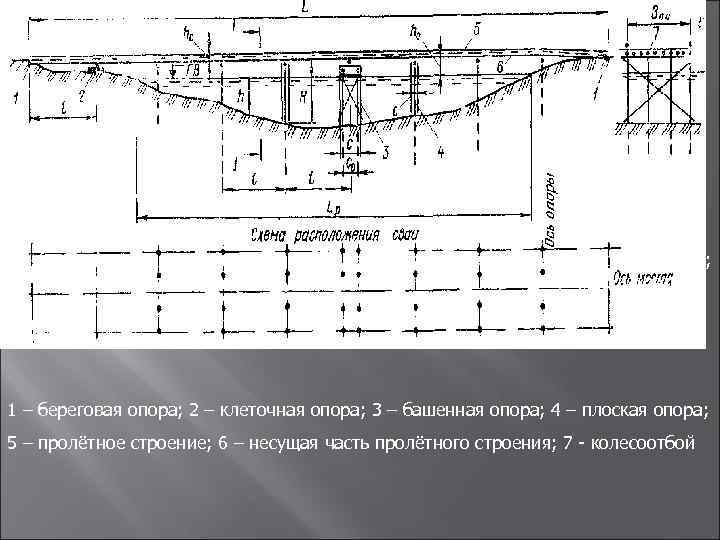 1 – coastal support; 2 – cell support; 3 – tower support; 4 – flat support; 5 – span structure; 6 – load-bearing part of the span; 7 wheel release


 The bridge axis is an imaginary line running in the middle of the roadway; The axis of the support is an imaginary line passing in the middle of the width of the support and perpendicular to the axis of the bridge; The line of the outermost piles (racks) of supports is an imaginary line running along the bridge along the axes of the outermost piles (racks) of the intermediate supports. Bridges in most cases are built across water barriers, which are characterized by a certain regime. The river regime is the behavior of the river throughout the year or during a given period of operation of the bridges. The river regime should be understood as a change in water horizons, the timing and nature of freeze-up, ice drift, a change in the speed of water flow, a change in the direction of flow jets, etc. Rivers change their water horizon throughout the year: in summer they become shallower, during heavy rains and when When snow melts, water rises, which is called a flood. Floods in summer are typical for mountain rivers, and in autumn and spring – for lowland rivers. In the spring, as a result of snow melting, most lowland rivers experience a large rise in water and overflow their banks. This condition on rivers is called flood.
 The characteristics of floods and floods on each river vary from year to year. Therefore, bridges are built for a certain period of operation and are designed for the maximum lift that is possible during this period. In the characteristics of a watercourse, the following designations are accepted: HWL - high water level - the highest water level observed in a given river over several years during a flood or flood period. LWL – low water level – the most stable summer and winter level characteristic of this river; RSU – estimated navigable level; RUVV - design high water level (the highest water level that can be expected for the entire period of operation of the bridge); UVL – high ice drift level – water level at the highest ice drift; UNL – low ice drift level – water level at the lowest ice drift.
 The living cross-section of a river is the part of the cross-section of the river that is washed by water. The main channel is a living section at the low water horizon. The left and right floodplains are parts of the cross-section of the river, bounded on the right and left by low-water edges.
 Fourth question. Classification of bridges by purpose, by systems, by materials, by location, roadway, by service life, by length and dimensions of the roadway. A bridge crossing over a water barrier and the purpose of the elements that make it up. Classification of bridges Military bridges are classified according to various criteria. Based on their service life, bridges can be short-term or temporary. Short term. bridges are designed for a short service life (from several weeks to one year) and have a simple design. These bridges do not provide passage for ice drift or high water. The speed on short-term bridges may be lower than the speed on the road. Let us allow additional restrictions on the speed of vehicles on short-term bridges and their weight, depending on operating conditions. Short-term bridges can be low-water, underwater and floating bridges, as well as bridges in the form of superstructures of spans and supports on the preserved structures of destroyed capital structures. During short-term restoration, paddle, ice and pile ice crossings are also organized.
 Temporary bridges are designed for normal year-round operation and are designed for a service life of 3-5 years with a constant load capacity of the bridge and without a significant reduction in the speed of transport on the bridge compared to its movement on other sections of the road. Temporary bridges can be: high-water bridges on rigid supports, built from local materials bypassing destroyed capital bridges; high-water bridges on rigid supports, assembled from salvage property. In wartime conditions, most often it is necessary to build short-term bridges and less often - temporary ones. According to the conditions for ensuring the passage of high waters and ice drift, bridges are divided into high-water, low-water, underwater and smooth.
 High-water bridges are built taking into account year-round operation, have significant spans, large heights of supports and a relatively complex design. High-water wooden bridge over the Oka River
 Low-water bridges have a minimal elevation of the spans above the water and do not provide passage for high flood waters and ice drift. These bridges have small spans, a simple design and a short (within the season) service life.
 In underwater bridges, the roadway of the span is located 30-50 cm below the water level. They are more resistant to the damaging factors of an atomic explosion (shock wave, light radiation), and also provide more reliable camouflage of the bridge crossing as a whole. Tank crossing over the Prolet underwater bridge
 Floating bridges are installed on floating supports or in the form of a floating strip. For the passage of vessels, the installation of exit links is provided. During floods and ice drifts, floating bridges are dismantled.
 Based on the width of the roadway, bridges are classified into single-track and double-track. Based on the type of building materials, bridges are divided into wooden, metal, reinforced concrete, and combined. By size, bridges are divided into small, medium and large. Small bridges are called bridges up to 25 m long, medium - from 25 to 100 m, large - more than 100 m. According to the system (scheme of the static operation of the span), bridges are divided into beam, strut, truss, arch, suspension, combined. The choice of a bridge system and the characteristic features of its design depend on the required bridge spans, the height of the supports, the magnitude of the planned loads, as well as the available building materials. Based on the nature of the structures used, a distinction is made between bridges made from standard industrial-made structures and those made from local military-made materials. Service bridges include pontoon parks and collapsible bridges on rigid supports. Their advantages are reusability, short assembly time, and mobility during transportation. For elements of military-made bridges, predominantly local materials are used. They can be prepared in advance or during bridge construction. As a rule, blocks of purlins, blocks of roadway panels, track blocks, Gau Zhuravsky trusses, board and nail trusses, etc. are prefabricated in advance. This ensures a timely solution to the problems of high-speed construction of bridges in a combat situation.
 Based on their load capacity, bridges are classified into high, normal, low and low load capacity. Bridges with increased (80 t) load capacity ensure the movement of all existing loads. Bridges of normal (60 t) load capacity are recommended to be built on military roads. Bridges of reduced (25 and 40 tons) load capacity are built on roads where the actual freight traffic corresponds to this load capacity. Light-duty bridges are built on roads intended exclusively for road transport.
 Elements of a bridge crossing A complex of engineering structures that ensures normal processing and continuous operation of a bridge during its planned service life is called a bridge crossing. The bridge crossing consists of a bridge, approaches to the bridge, ice cutters, regulatory structures and bottom reinforcement devices. Depending on local conditions and combat conditions, some elements of the bridge crossing may be missing, with the exception of approaches to the bridge and the bridge itself. The bridge is the main structure of the bridge crossing. It consists of spans and supports. The span structure is designed to cover the gap (span) between the supports and consists of a roadway and a load-bearing part.
 The roadway creates a surface that is comfortable for driving, absorbs forces from moving loads and transfers these forces to the load-bearing part. The load-bearing part is designed to absorb loads from the roadway and transfer forces from these loads and its own weight to the supports. The greater the distance between adjacent supports, the more complex the design of the supporting part, and vice versa. For small distances (spans), the simplest load-bearing part is used in the form of a series of beams, called girders, laid on supports. For large spans, various types of trusses or metal beams with a solid wall of large sections and height dimensions are used as a load-bearing part. The supports are designed to support the spans at the required height and to transfer all the forces from the spans to the ground. In military bridge construction, bridges made of wood are used. Depending on the characteristics of the barrier, they can be pile, frame, pile-frame, cage or cord. Bridge approaches are sections of the road that are directly adjacent to the bridge, connecting its roadway with the road. Depending on the terrain conditions, they can be arranged in the form of an embankment or excavation.
 It is recommended to set the height of the approach embankment to no more than 1.5-2 m; at higher heights, it is more advantageous to replace the approach embankment with a bridge overpass on rigid supports. To protect against flooding of approaches with water, the height of the embankment should be higher than the expected high water level. For approaches to low-water bridges - at least 1 m. Directly at the bridge, approaches in the form of an embankment end with a conical fill or fence walls. The steepness of the slopes of the embankments, depending on its height, the speed of water flow along the embankment, the type of soil of the embankment itself and the bottom of the slope, is assumed to be 1: 1–1: 2. And for clay and loamy soils, strong waves and fast flow speeds - 1: 2, 5 1: 3. The steepness of the frontal slopes of the cones is assigned from 1: 1 to 1: 1.75. When the height of the approach embankment is more than 1.5 m, a restriction must be installed for the safety of traffic on the embankment in the form of vertical grooves installed every 1.5 m. 5 2 m on both sides along the edge of the roadbed. At a distance of 150-200 m from the bridge, the approaches should be widened, if possible, with a length of at least 100 m to accommodate damaged vehicles, ease their detour, and also to stop transport in the event of an enemy air attack. Near the approaches, shelters are arranged for personnel and equipment. In areas of approaches where there are natural shelters, exits are made and signs are placed indicating the presence of shelters. In bridge crossings, when long embankments are built on floodplains, during the period of passage of high flood waters, a strong constraint is formed on the living cross-section of the water flow. Near the cones, along the embankments, at the supports and ice cutters of the bridge, various vortices and whirlpools are formed, which lead to the erosion of their foundations. To eliminate erosion and ensure the smooth flow of flood waters, regulatory structures (stream guide dams, traverses, etc.) are installed under the bridge.
 Stream dikes are usually built on rivers with large floodplains on one or both banks. The outline of the dams in plan is determined based on data from studying river regimes. It can be curved or consist of curved parts and a straight insert. Often the outline of dams is determined by a parabola. The head of the dam is arranged up to 4-5 m wide, the slopes of the river part are arranged no steeper than 1: 2. To protect the embankment from erosion by flood waters, traverses are installed on the upstream side, and sometimes on the downstream side, which deflect the currents arising along the embankment. Regulatory structures are, as a rule, not erected during the construction of bridges on the main road, but they have to be brought into working condition and operated during the temporary restoration of bridges over large water barriers. On rivers that are covered with ice in winter, the supports of wooden bridges need to be protected from damage that may occur as a result of exposure to ice during ice drift. The impact of ice poses the greatest danger to bridges, especially during intense ice drift due to the high force of ice impacts, as well as due to the formation of congestion. To protect the supports, ice cutters are installed, the purpose of which is to crush large ice floes, protect the bridge supports from impacts of ice floes and direct floating ice floes into the spans of the bridge. Since the strongest ice drift is observed in places of greatest depths and river speeds, the main attention should be paid to protecting the river supports of the bridge. In most cases, supports in floodplain areas can be protected with lighter ice cutters, while coastal ones, as a rule, do not require protection from ice. Based on their location, ice cutters are divided into bridge cutters and outpost cutters.

 Bridge bridges can have a structure combined with supports, or in the form of separate structures at a certain distance from the supports. The distance from the ice cutters to the supports is determined depending on the speed of the current. If, during a fast flow, the ice cutters are placed too close to the support, then the ice floes, breaking against the ice cutters, may have time to damage the supports. Therefore, with a fast flow, ice cutters are removed from the supports at a greater distance than with a weak flow. The width of the ice cutter is set to be slightly larger than the width of the support or, in extreme cases, equal to it. On rivers with particularly strong ice drift, they do not limit themselves to one row of ice cutters, but place a second row of ice cutters, called outpost ones, in front of the first row. They take on the most powerful impacts of ice fields and break them into smaller pieces. Such ice cutters are installed only in the main channel, where the current speeds are highest. When constructing military high-water bridges, the following types of ice cutters are used: normal cluster, reinforced cluster, flat (single-row, double-row), cylindrical and tent-shaped. Bottom and bank protection devices help to increase the service life of bridge crossings.

The price for this document is not yet known. Click the "Buy" button and place your order and we will send you the price.
We have been distributing regulatory documents since 1999. We punch checks, pay taxes, accept all legal forms of payment without additional interest. Our clients are protected by law. LLC "CNTI Normocontrol"
Our prices are lower than other places because we work directly with document providers.
Delivery methods
- Express courier delivery (1-3 days)
- Courier delivery (7 days)
- Pickup from the Moscow office
- Russian Post
The Military Low Water Bridges Manual provides guidance on the construction of low water and underwater bridges and overpasses on rigid supports constructed from local materials.
Chapter 2. Engineering exploration of the bridge construction area
Chapter 3. Structures of wooden spans of low-water bridges
1. Block spans
Superstructures made of track blocks
Superstructures made from blocks of purlins and roadway panels
a) Blocks of simple runs
b) Blocks of complex runs
c) Blocks of composite purlins
2. Span structures from individual elements with simple and complex purlins
roadway
Simple runs
Complex runs
Chapter 4. Designs of metal spans of low-water bridges
1. Block spans
Blocks of four runs
Blocks of two runs
roadway
2. Superstructures made of individual elements
Load-bearing structure with simple purlins and packages
Load-bearing structure with composite purlins
roadway
Chapter 5. Intermediate supports of low-water bridges
1. Pile supports
2. Frame wooden supports
3. Cellular supports
4. Ensuring longitudinal stability of the bridge
Chapter 6. Coastal supports and interface of the bridge with the banks
Chapter 7. Manufacturing and transportation of bridge structures
1. General Provisions
2. Manufacturing of structures for low-water wooden bridges
Logging work
Sawmill work
Works on the manufacture of wooden bridge structures
Manufacturing of track blocks
Assembly of purlin blocks
Manufacturing of span structures from blocks of purlins and roadway panels
Features of assembling blocks of complex runs
Manufacturing of composite purlins on steel cylindrical dowels and assembly of blocks from two purlins
Manufacturing of piles
Manufacturing of nozzles and support supports
Manufacturing of elements and assembly of frame supports
Peculiarities of manufacturing elements of bridge structures during the construction of bridges from individual elements
3. Manufacturing of metal bridge structures
General provisions
Manufacturing of metal elements
Manufacturing of roadway elements
Manufacturing of purlin blocks
Manufacturing of spans from individual elements
4. Transportation of bridge structures
Chapter 8. Construction of low-water bridges
1. General Provisions
2. Breakdown of the bridge axis and support axes
3. Means of mechanization of work during the construction of bridges
4. Depth of driving piles in supports
5. Organization of work during the construction of low-water bridges
General provisions
Construction of bridges on pile supports using a set of bridge construction tools KMS
Construction of bridges on pile supports using DM-150 diesel hammers with single-boom OSK pile drivers and DB-45 diesel hammers with PUS-1 devices for installing piles
Construction of bridges on frame supports using ferries with jacks from the KMS kit
Construction of bank supports and interfaces of the bridge with the banks
Construction of bridges from individual elements
Features of the construction of double-track bridges on pile supports
Features of the construction of bridges on pile supports with increased spans
Chapter 9. Underwater bridges
1. General Provisions
2. Design features of intermediate supports
3. Coastal supports and interface of the underwater bridge with the banks
4. Design features of underwater bridge spans
5. Features of the construction of underwater bridges on pile supports
6. Features of the construction of underwater bridges on frame supports
7. Features of the construction of underwater bridges with metal girders
Chapter 10. Features of the design and construction of bridges in special conditions
1. Winter bridges
2. Combined bridges
3. Bridges over water obstacles with high current speeds and rocky bottoms
General provisions
Intermediate supports
Features of building bridges on rivers with high flow speeds
4. Bridges over canals and narrow barriers
Chapter 11. Overpasses
Chapter 12. Operation and maintenance of bridges
1. Acceptance of bridges
2. Rules for driving on bridges
3. Operation of bridges
4. Elimination of damaged bridge elements
5. Preparing bridges to handle ice drift and floods
6. Passage of ice drift and flood
7. Bridge security
Chapter 13. Determination of bridge load capacity
1. General Provisions
2. Bridge inspection
3. Determination of the load capacity of steel and wooden bridges
Chapter 14. Calculation of low-water bridges
1. Basic provisions
2. Calculation of flooring and crossbars
3. Calculation of runs
4. Calculation of supports
Determination of pressures
Selection of pile and rack sections
Selection of nozzle and bed sections
Calculation of linings under the support of a frame support or under the coastal support
5. Example of calculation of a low-water bridge on pile supports
Appendix 1. Timber data
Appendix 2. Data on rolled metal beams and rails
Appendix 3. Data on composite purlins made of rolled I-beams and rails
Appendix 4. Data on forgings and nails
Appendix 5. Data on ropes and cables
Appendix 6. Determination of the strength of coniferous wood using the firearm method
Appendix 7. Engineering survey card for the bridge construction area
Appendix 8. Data on engineering reconnaissance means
Appendix 9. Forest exploration
Appendix 10. Field design of a low-water bridge on pile supports
Appendix 11. Specification of bridge elements and structures
Appendix 12. Diagram of the bridge structures procurement point and work schedule
Appendix 13. Tactical and technical characteristics of bridge construction equipment
Appendix 14. Data on machines for welding and cutting metal
Appendix 15. Data on truck cranes
Appendix 16. Vehicle data
Appendix 17. Consumption of timber and metal per 1 linear meter of wooden bridge span
Appendix 18. Indicative standards for the construction of low-water bridges
This document is located in:
Organizations:
| 05.11.1964 | Approved | ||
|---|---|---|---|
| Published | 1965 |
Guidelines for the Use of Expanded-Clay Lightweight Concrete In Road and Highway Bridges
page 1

page 2

page 3

page 4

page 5

page 6

page 7

page 8

page 9

page 10

page 11

page 12

page 13

page 14

page 15

page 16

page 17

page 18

page 19

page 20

page 21

page 22

page 23

page 24

page 25

page 26

page 27

page 28

page 29

page 30
USSR MINISTRY OF DEFENSE
MANAGEMENT- ON MILITARY, LOW-WATER BRIDGES
MILITARY PUBLISHING HOUSE OF THE USSR MINISTRY OF DEFENSE MOSCOW-1965
USSR MINISTRY OF DEFENSE
APPROVED
MANAGEMENT over MILITARY LOW-WATER BRIDGES
MILITARY PUBLISHING HOUSE OF THE USSR MINISTRY OF DEFENSE MOSCOW - 1965
ki, should not exceed 1:500 in the vertical plane and I:250 in the horizontal plane of the beam;
The local curvature of the beam, determined by the ratio of the arrow of the local bend (dent) to its length, should not exceed 1:200 for chords and 1:100 for the wall; with greater curvature (general and local), the beams must be straightened before the manufacture of bridge structures begins;
The damage to beams (rails) by rust should not exceed 1 mm, with greater damage by rust, but not more than 2 mm, the bearing capacity of the run is recalculated;
Cracks and local damage (flaws) in beams are not allowed;
Wear of railway rail heads should not exceed 15 mn in height;
Beams (rails) exposed to flames cannot be used if they have deformations, burns or cracks; signs of metal burnout are melted areas and scale films. Data on rolled I-beams and channel beams, as well as broad gauge railway rails are given in Appendix 2.
18. Metal forgings (pins, staples, clamps) necessary for connecting elements of bridge structures are made of round, square and strip steel.
The necessary data on metal forgings, as well as round steel and nails are given in Appendix 4.
Data on hemp ropes and steel cables are given in Appendix 5.
ENGINEERING EXPLORATION OF THE BRIDGE CONSTRUCTION AREA
19. The purpose of engineering reconnaissance of the bridge construction area is to obtain data that makes it possible to:
Selecting a bridge construction site (if it is not specified) and approaches to it;
Determination of places for procurement of materials and bridge elements;
Selection of delivery routes for prepared materials and bridge elements;
Drawing up a bridge diagram;
Determining the quantity of necessary materials and elements;
Making decisions on the organization of work.
20. Engineering reconnaissance establishes:
The main features of the obstacle and the place where the bridge was built (the nature of the bottom soil, banks and approaches, profiles of the banks and approaches to the bridge, the presence and condition of roads approaching the bridge, etc.);
Profiles of the live (cross-section) section of a water or other barrier in places possible for the construction of a bridge;
The regime of the water barrier in the area where the bridge was built (speed and characteristics of the current, low-water horizons, possible fluctuations in the water horizon during the operation of the bridge);
The presence of dams, locks and other hydraulic structures and the nature of their possible impact on
operation of the bridge under construction in cases of water leakage or destruction of these structures;
Availability of necessary building materials in the bridge construction area (standing timber, warehouses of finished forest materials, metal beams, metal for forgings, materials for various buildings, etc.);
Availability of production facilities that can be used for the manufacture of bridge elements and forgings;
Availability and condition of routes for transporting materials and bridge elements from the procurement site to the barrier;
Necessary camouflage measures in places where materials and elements are procured, in the place where the bridge is built, as well as in the place where false bridges are built;
The nature and scope of work on the construction of shelters for crews, mechanization equipment and materials from possible enemy influences (trenches, cracks, etc.);
The presence and nature of obstacles on a water barrier and on the approaches to it.
21. To conduct engineering reconnaissance, depending on the width of the water barrier, a patrol consisting of:
With an obstacle width of no more than 50 m, up to one squad led by an officer, with a sergeant with two or three soldiers assigned to reconnaissance of materials, and the officer leading the reconnaissance with the rest of the soldiers carries out reconnaissance work on the water barrier;
If the width of the obstacle is more than 50 m - up to a platoon with two officers; the officer in charge of reconnaissance conducts reconnaissance work on a water barrier with soldiers; another officer and soldiers are assigned to scout materials.
22. Engineering reconnaissance data is entered into the engineering reconnaissance card (Appendix 7) and onto a map at a scale of 1:100,000-1:500,000. A profile of the live section of the obstacle along the axis of the bridge is attached to the engineering survey card (Appendix 7).
The map shows: the axis of the bridge, approaches to it, places of procurement of timber and bridge structures, routes for the supply of materials and elements from the procurement site.
routes to the construction site, the location of barriers and hydraulic structures, indicating their nature.
On the drawn profile of the live cross-section of the obstacle, the following is indicated: the speed of the current, possible changes in the water horizon during the operation of the bridge, the nature of the soil of the bottom and banks, and the slopes of the banks.
23. The patrol assigned to engineering reconnaissance must have a map, compass, sapper rangefinder, binoculars, field hydrometric turntable or hydrospeedometer, engineering reconnaissance echo sounder (IREL) or river reconnaissance apparatus (AR-2), bottom probes, weight striker, measuring tapes or tracing cords, thin cable or wire, slats or poles with divisions, level, plumb line, entrenching tool, swimming suits, boats. In addition, the patrol must be armed with reconnaissance and obstacle crossing equipment, as well as one or two armored reconnaissance vehicles (BRDM) and communications equipment.
24. When conducting engineering reconnaissance, depending on the situation and the nature of the water barrier, the following methods are used to obtain the necessary data:
The profile of the live cross-section of a water barrier is taken using an engineering reconnaissance echo sounder (IREL), a river reconnaissance apparatus (AR-2) and direct measurements;
The width of the water barrier is determined by a sapper rangefinder, binoculars, theodolite, geometric method and direct measurement;
The speed of water flow is measured with a hydrometer, hydrospeedometer or float;
The nature of the soil of the bottom, banks and approaches is determined with a bottom probe, and the density of the soil of the banks is determined with a weight striker;
Profiles of banks and approaches are removed by leveling or spirit level.
25. When choosing a bridge construction site, the following tactical requirements are taken into account:
If possible, locate bridges, especially underwater ones, in bends or on sections of the river separated by rifts, characterized by increased protective
properties in relation to the action of surface waves from a nuclear explosion;
Bridges should not be built in order to reduce the impact of enemy aircraft on them near populated areas, especially large ones and located on railway lines, warehouses, bases, etc.;
The distance between adjacent bridges, in order to exclude the possibility of simultaneous destruction of several bridges by one nuclear explosion, must be no less than twice the safe distance corresponding to the highest probable power of the nuclear weapon;
The approaches chosen for the bridge should be discreet, but ensure the movement of vehicles without delays or congestion;
The bridge construction area must allow for the installation of shelters for calculations, mechanisms, prepared elements and materials.
26. When choosing a bridge construction site, the following technical requirements should also be taken into account:
If possible, locate the bridge on a section of the river with the smallest width and depth of water, with a smooth change in depth and acceptable ground conditions;
It is advisable to place the bridge alignment on a straight section of the river with a regular straight-flowing flow;
It is necessary to assign the axis of the bridge perpendicular to the direction of the flow, and if the movement of the flow is not correct enough - perpendicular to the direction of the flow in the main, deepest part of the channel;
If it is necessary to build a bridge near the mouth of a tributary, remove the bridge at least 100-150 m from the mouth of the tributary downstream or at least 30 m upstream;
You should avoid such places for building bridges that require significant work on the construction of approaches and do not provide convenient placement of prepared elements and materials for building the bridge.
27. Removing the profile of the live section of the river with an IREL engineering reconnaissance echo sounder is carried out in accordance with the instructions of the IREL Description and Instructions
tion for its operation, and the river reconnaissance apparatus AR-2 - in accordance with the instructions of Appendix 8.
28. To obtain a profile of the live cross-section of the river, the width is measured by direct measurement and at the same time the water depth is determined in accordance with the instructions of Art. 29 and 30.
29. Direct measurement of the width of the river is carried out by pulling a cable, tracing cord, rope, wire, equipped with marks every 1-2 m, from one bank to the other. At night, to ensure visibility, scraps of white material are tied to them. On large water obstacles, steel cables are used, tensioned using winches, gates or a floating machine. In order to eliminate significant sagging, the cable is supported by buoys or boats.
30. Direct measurement of depths is carried out using a pole, hook, slats or lot, and simultaneously with measuring the width of the river. The measurement is taken from a floating vehicle or boat moving along the cable along the intended axis of the bridge. Distances between depth measurement points are assigned depending on the width of the water barrier (5 m on rivers up to 100 meters wide and 7-10 m on wider rivers) and taking into account the presence of significant local changes in depths that require additional measurements.
When building bridges on frame supports, the water depth is measured at the places where the supports are installed, at three points along the axis of the bridge and at the ends of the tracks.
31. Measuring the width of the river with a sapper rangefinder is carried out in accordance with the instructions in the Instructions for working with a sapper rangefinder and Appendix 8.
32. When measuring the width of the river with binoculars, they are sighted from parking lot A (Fig. 2) at two preferably vertical objects located at the edge of the opposite bank, and on the binocular rangefinder scale the number of divisions n is obtained that fits between these objects. Then
15
With the publication of this Manual, the Manual for Engineering Troops “Low-Water Bridges,” ed. 1955
GENERAL PROVISIONS
1. The Manual on Military Low-Water Bridges contains instructions for the construction of low-water and underwater bridges and overpasses on rigid supports constructed from local materials.
2. Bridges on rigid supports made of local materials are built on the routes of troop movement through various types of obstacles:
To replace bridges from regular crossing facilities in order to quickly release them and move them to subsequent obstacles;
In combination with floating bridges across wide water barriers;
In cases where the use of standard means is impossible or inappropriate;
When restoring destroyed permanent bridges.
3. Military bridges on rigid supports include low-water and underwater bridges, overpasses, as well as high-water bridges.
Low-water bridges are built without taking into account the possibility of passage under them of strong ice drift, high waters and ships (on navigable rivers). These bridges have small spans, a simple design and a short service life.
Underwater bridges differ from low-water bridges in that the roadway during operation is under water, which contributes to greater secrecy and increased survivability when exposed to a nuclear explosion.
Overpasses are erected at the intersection of roads with heavy traffic in order to ensure the movement of loads at two levels.
High-water bridges are built taking into account their operation for a long time, the possibility of passing high waters, ice drift and ships under them (on navigable rivers). These bridges have significant spans, large heights of supports and a relatively complex structure.
4. The following basic requirements are imposed on low-water and underwater bridges, as well as overpasses built from local materials:
High pace of work, ensuring the construction of bridges within the given, usually short, time frame;
Possibly less labor intensity of work performed on the barrier, helping to reduce the required calculations and time for building bridges;
Reliability of bridge structures, ensuring repeated passage of design loads;
The survivability of bridges, ensuring, if possible, equal strength of individual parts and fastenings when exposed to a nuclear explosion, as well as the ability to pass loads if individual elements are damaged and quickly restore the bridge in the event of partial destruction;
The speed of mastering by calculations the methods of manufacturing bridge structures and methods of building bridges in various conditions.
Compliance with these requirements is ensured by:
Organization of work on a wide front with maximum use of mechanization for all types of work;
Widespread use of pre-fabricated elements and blocks, adapted for transporting them to the construction site and ensuring the possibility of carrying out mainly only assembly work on the barrier;
The use of simple bridge structures that allow the widespread use of mechanization in the manufacture and assembly of bridges on the barrier.
5. A military low-water bridge on rigid supports (Fig. 1) consists of a span and supports. The span structure is formed from the roadway and load-bearing parts. The roadway along which loads move transfers their pressure to the load-bearing part. The load-bearing part takes up the pressure from the load passing along the bridge and the own weight of the span and transfers them to the supports.
The supports, supporting the superstructure, transfer pressure from the transmitted loads and the bridge's own weight to the ground. The supports located on the banks are called coastal, and the rest - intermediate.
6. The span structure of low-water and underwater bridges and overpasses is based on the simplest beam split system. Its design is formed from:
Separate purlins of various types (simple, complex, composite) supporting the roadway made of boards;
Blocks of various types (track blocks and blocks of purlins with roadway shields).
7. In military bridges, the following basic definitions and designations are used (Fig. 1):
L p - river width along the calculated horizon;
Bridge length L is the distance between the axes of the shore supports;
Bridge span / 0 - distance between the axes of adjacent supports;
Design span I of bending elements is the distance between the axes of their support;
Carrier^\l
part" 1" g 1
Line of extreme piles
Rice. I. Scheme of a low-water bridge
Bridge axis
Support axis - a line running in the middle of the support width and perpendicular to the axis of the bridge;
The line of the outermost piles (racks) of supports is a line running along the bridge along the axes of the outermost piles (racks) of the intermediate supports.
8. The designs given in the Manual take into account the impact of the following loads on the bridge:
Self-weight of bridge elements;
Movable tracked or wheeled load;
Horizontal wind pressure;
Transverse force from the rotation of the moving load on the bridge;
Braking force from moving load;
Shock wave of a nuclear explosion.
9. The load capacity of low-water bridges is characterized by the largest weight of a single tracked load carried over the bridge.
For these bridges, two load capacities are installed on rigid supports made of local materials - 60 p 25 t.
Bridges with a load capacity of 60 tons can carry:
Track loads weighing up to 60 g;
Wheel loads with pressure on the wheel up to 8.0 g;
Road trains in the form of a tractor with a heavy-duty trailer with a total weight of up to 90 tons.
Bridges with a load capacity of 25 tons can carry:
Track loads weighing up to 25 g;
Wheeled with pressure per wheel up to 4.0 g.
Data on the calculated moving load are given
10. The dead weight of bridge structures is determined according to the designed dimensions or according to the tables given in Appendix 17.
When determining the dead weight of bridge structures, the following calculated volumetric weights of wood and metal are taken:
Pine, spruce, poplar - 600 kg/m3\
Larch, birch, beech - 700 kg/m3\
Oak - 800 kg/m3;
Siberian fir - 500 kg/m3;
Steel - 7850 kg/m3.
11. Low-water and underwater bridges, as well as overpasses, are usually built as single-track; Only low-water bridges on roads with heavy traffic in two lanes are built as double-track bridges. Double-track bridges are built with a load capacity of 60 tons.
The width of the roadway of military bridges on rigid supports is:
For single-track bridges with a load capacity of 60 g - 4.2 m\
For single-track bridges with a load capacity of 25 g - 3.8 m;
For double-track bridges - 6.0 m.
Single-track bridges are allowed to carry moving loads with displacement close to one of the wheel guards.
On double-track bridges, all wheeled and tracked loads weighing 25 g or less are carried in two columns, and loads with a total weight of more than 25 tons are carried in one column with a displacement relative to the bridge axis of no more than 0.75 m.
12. When constructing low-water bridges on rivers with flotillas operating on them, if necessary, provide for the installation of exit links for the passage of ships.
13. For the construction of bridges from local materials
Forest materials, rolled steel beams, broad gauge railway rails, forgings (bolts, pins, clamps, staples), nails, as well as various auxiliary materials are used.
14. Forest materials are harvested in the forest, used found in warehouses, and also obtained from the dismantling of various buildings.
The most widely used wood for building bridges is pine and spruce.
The necessary data on timber is given in Appendix 1.
15. The following requirements apply to forest materials used for the construction of military bridges:
Rot, wormhole (except superficial, from bark beetle), curling, loose and tobacco knots are not allowed;
Healthy knots are allowed with a diameter of no more than / 4 the diameter of the log or the width of the timber and board;
Cracks are allowed with a depth of no more than */3 the diameter of the log or the thickness of the timber and boards over each length of no more than */3 the length of the element;
Cross-layering is allowed no more than 15% in logs and 8% in beams and boards.
The most straight-layered timber with the fewest knots and cracks is selected for the outer purlins, transverse flooring, attachments and support supports. For piles and racks of frame supports, straight-layered logs are used, but the use of logs with knots and cracks is also allowed.
16. If there is any doubt about the quality of timber materials intended for the construction of bridges, their actual bending strength is determined using a Makarov pistol using the firearm method described in Appendix 6.
Determined by this method, the actual bending strength of timber suitable for use in bridge construction should not be less than 250 kg/cm 2 .
17. Rolled beams and rails used for bridges must meet the following requirements:
The total curvature of the beam (rail), determined by the ratio of the maximum bending arrow to the length of the beam
(sixties-eighties)
Pontoon-bridge park PMP

The term “pontoon-bridge park” means a set of equipment for building bridges across water barriers, the roadway of which rests on floating supports (pontoons). From the same property, as a rule, ferries can be assembled to ferry people and equipment across water barriers. In addition, the fleet may also include vehicles for transporting property (but not necessarily).
The pontoon-bridge fleet of the "PMP" brand, which has been in service with the Soviet Army since 1962, is intended for building pontoon bridges up to 227 meters long for 60t loads, pontoon bridges up to 382 meters long for 20t loads, as well as for assembling ferries of various carrying capacities. Allowable current speed is up to 2.5m. per second Unlike all its predecessors, the PMP bridge does not have separate pontoons and a separate roadway. Its upper part of the pontoons is the roadway
The PMP fleet includes 32 river links, 4 coastal links, 2 pavements, 12 towing boats. To transport links and pavements, 38 specially converted KRAZ-255V vehicles are used (the first series of the fleet were transported by KRAZ-214 vehicles). Boats of the BMK-90, BMK-130 or BMK-150 type are towed on trailers or their own wheeled chassis by 12 Zil-130 (Zil-157) vehicles. When the fleet is equipped with BMK-T type boats, these boats are transported by 12 KRAZ-255V vehicles on vehicle platforms.
One KRAZ vehicle transports one link, consisting of two middle and two outer pontoons, connected by hinge joints. In the transport position, the link is transported folded on a vehicle platform. The picture shows a car with a river link. 
In the picture showing the car with a link at the rear, two middle pontoons of a rectangular shape and two outer ones of a rounded shape are clearly visible. The bank link differs from the river link in its shape, which allows the bridge to be interfaced with the bank and the presence of folding ramps.
The flight crew should consist of a driver and two pontoons.  According to the staff, the team consists of a pontoon driver and a pontooner. When building a bridge or assembling a ferry, the car drives in reverse into the water so that the depth at the point of release is about 1 meter; then brakes sharply; the pontoon located next to the car releases the stopper; and the link, lying freely on the platform rollers, rolls into the water.
 After entering the water, under the influence of buoyancy forces and torsion joints, the link opens. The picture shows the link at the moment of opening (rear view). The link at this moment is held near the shore by a mooring line, the second end of which is attached to the car. The pontoon driver and the pontooner climb onto the deck, lock the bottom and deck locks, thereby turning the link into a rigid structure.
 The picture shows the link in an open form (rear view). After locking the locks, the pontooners of neighboring links use hooks to bring their links together and connect them with locks. The bridge ribbon is thus assembled along the shore. The assembled bridge strip is held near the shore by mooring lines attached to the vehicles. As the tape is assembled, the machines drop the mooring lines and move to the collection area. The width of the roadway is 6.5 meters.
 After the bridge strip is assembled, with the help of towing boats it turns across the river, the coastal links are secured with mooring lines near the shore, and the strip itself is held in the current by boats until the anchors available on each link are delivered and dropped. After tensioning the anchor cables and aligning the tape, the boats disconnect and leave.
  The picture shows part of the bridge tape (top view). The 6.5m wide roadway is shown in dark green. This width of the roadway allows tanks to move across the bridge at speeds of up to 30 km. per hour, and for wheeled vehicles without speed limits. Moreover, wheeled vehicles can move along the bridge in two columns, or simultaneous movement along the bridge in both directions is possible. With this assembly scheme from one set
  Who can assemble a bridge for 60t loads? length up to 227m.
For loads of 20t. The bridge layout is different. The link opens on one side and rotates 180 degrees. In this case, the bridge tape looks like this: “a link in its usual form - an expanded link - a link in its usual form - …”. The width of the roadway is then only 3.3 m, but from one set you can assemble a mo  st 382 meters long.
To ferry equipment and personnel across water obstacles, the width of which exceeds the capabilities of the bridge, from one set of PMP you can assemble 16 ferries with a carrying capacity of 40 tons, or 12 - 60 tons, or 8 - 80 tons, or 4,120 tons, or 4-170 tons . Towing of ferries is carried out by towing boats. Each ferry represents a separate section of the bridge.
The lining consists of a metal strip laid on the platform of a KRAZ vehicle, consisting of individual links, hingedly connected to each other. The pavement is designed to allow vehicles being transported to enter the bridge in muddy bank conditions. The use of pavement is permitted only in time of war, because... tanks render the pavement completely unusable in one crossing.
The complete PMP fleet is in service with an army or front-line separate pontoon-bridge battalion (OPOMB). The battalion consists of two pontoon companies (16 river, 2 coastal units, 6 boats and 1 liner in the company), a separate engineering and technical platoon armed with a set of bridge construction equipment KMS (or a bridge construction installation USM), a set of heavy mechanized bridge TMM. This platoon is designed to ensure the closure of banks using small bridges on supports when there is a lack of pontoons. In addition, the battalion has a repair platoon and a maintenance platoon. In total there are about 250 people in the battalion.
In addition, the engineering battalion of the tank (motorized rifle) division has a pontoon company (0.5 sets of infantry fighting vehicles). From this half of the kit you can assemble a half-length bridge or a corresponding number of transport ferries.
 Time to build a bridge for 60t loads. in the daytime 30 minutes, for loads of 20 tons. during the day 50 min. At night the standard doubles.
According to the combat regulations, the battalion moves to the river in the first echelon of the division. The construction of the bridge begins after the crossing of the water barrier by the first wave of landing forces on floating equipment (infantry fighting vehicles, armored personnel carriers, PTS) as soon as the possibility of shelling the water surface of the barrier from small arms and mortars is excluded.
From the author. By 1978, the Americans, without further ado, simply copied the PMP fleet with the only difference being that the pontoons were made not of steel, but of aluminum, and placed them on their cars. And even the number of bolts on the access hatches to the inside of the pontoon is the same.
In the sixties, Czechoslovakia produced a fleet of PMPs under license, placing them on its four-axle Tatra vehicles.
At the end of the eighties, a later version of the PMP fleet called PPS-84 was produced. This fleet was based on KRAZ-260 vehicles and had BMK-460 boats.
In the summer of 1979, the 1257th separate pontoon-bridge battalion of the Central Group of Forces under the command of Lieutenant Colonel A.V. Skryagin. during exercises near the village of Horni Pochapli on the Laba (Elbe) River, it opened a bridge during the day in 13 minutes 42 seconds, at night in conditions of complete blackout in 29 minutes 54 seconds.
Theoretically, you can connect as many links as you like into one strip. The author observed the assembly of a bridge from two sets of PMP (430 meters). However, such a tape is difficult to keep in the flow. The anchors do not hold, and the motors of the boats holding the bridge quickly overheat. It is difficult for a commander to coordinate the work of a large number of boats. So the bridge is 227m. optimal. If the water barrier is wider, it is more advisable to cross by ferry.
For comparison: The predecessor of the PMP park, the TPP park, with approximately the same bridge length, was transported by 98 vehicles, assembled in 3-4 hours and required 995 people (pontoon-bridge regiment) to operate it.
Sources
1. Instructions for the material part and operation of the PMP pontoon-bridge park. Military publishing house of the USSR Ministry of Defense. Moscow 1966
2.Military engineering training. Tutorial. Military publishing house of the USSR Ministry of Defense. Moscow. 1982
 Educational goal: To form in students a creative attitude towards choosing a method of building a bridge. Educational goal 1. To give an idea of the technology and organization of the construction of military bridges and crossings. 2. To develop knowledge of organizing exploration of construction areas. 3. Instill the skill in the organization of PZMK. Type of lesson: Practical lesson with a platoon. Venue VMP class, No. 6. Material support Posters, slides, training manual “Military bridges on rigid supports”. Literature 1. Textbook “Military training of reserve officers of the road troops”. Part II, pp. 112 -140 2. Textbook “Bridges and crossings on the VAD”, pp. 114 -138.
 The first question is “Composition of the area for procurement of bridge structures. Timber harvesting technology” Second question “Organization of a point for procurement of bridge structures, its purpose and composition, sorting of logs and sawing of timber at field sawmills” Third question “Site for the production of elements of low-water wooden bridges, piles, nozzles, blocks of purlins, diagonal scrums, elements of coastal supports and roadways, production lines for the production of blocks of wooden spans” The fourth question is “Transportation of low-water bridge structures. Calculation of vehicle needs”
 The first question is “Composition of the area for procurement of bridge structures. Timber harvesting technology” The area for harvesting bridge structures includes: 1. cutting area; 2. plots; 3. skidding roads; 4. sorting area; 5. cross-cutting platform; 6. loading area; 7. routes of movement; 8. point for procurement of bridge structures. Harvesting of local timber, sawing of logs, manufacturing of elements and blocks of bridge structures are carried out in the area of procurement of bridge structures (RZMK), in which the cutting area is deployed and equipped (an area near a timber warehouse or a dismantled structure; cross-cutting site; point of procurement of bridge structures (PZMK); tracks supply of timber and removal of finished bridge structures. Two types of logging can be used: selective and clear-cut. In military conditions, it is advisable to carry out harvesting selectively, but with homogeneous forest tracts it is more profitable to carry out harvesting by clear-cutting. The divisions that carry out the harvesting of timber are equipped with
 necessary means of mechanization (chainsaws, hydraulic wedges KGM 1 A, felling poles, axes, crowbars, wagons). The cutting area is divided into plots 70–80 m wide, and they, in turn, are divided into apiaries 17–20 m wide. Felling is carried out, if possible, along existing clearings and roads. The direction of felling of cut trees depends on what skidding equipment is planned to be used. Using a hydraulic wedge or felling pole
 trees are felled at an angle of 30° to the drag. Trees in the drag strip are cut down flush with the ground, and in the remaining area the stump height is allowed to be no more than 30 cm. The depth of the cutting area in the direction of the drags is usually taken to be 0.3-0.5 km; can reach 1 km, but in order to limit idle runs of skidding equipment, the depth of development of the cutting area should not be increased. For felling, portable gas-powered saws and electric saws from power station kits are used. When selectively mining forests, it is advisable to use gas-powered saws, and when clearing forests, electric saws can also be used. Logging is carried out by dragging using skidders, and other means that have sufficient power and maneuverability depending on the terrain conditions can also be used. To skid the logs, apiary trails 5 m wide are laid in the middle of each plot, and from the plots to the cross-cutting area, main trails 7–9 m wide are laid. Logging is carried out by carts (several logs) and consists of the following operations: moving the tractor to the place where the cart is collected; pulling away the traction steel rope and chokers (if there is no second set, then time is lost in this operation); chokering of whips and collecting the cart with a winch; moving the tractor to the place of unloading and uncoupling the cart.
 Bucking and sorting of logs is carried out on a bucking platform, which is equipped with logs laid with their butts facing each other, which allows for a slope from the butt to the top and facilitates the rolling of the logs. Bucking is carried out in accordance with the drawn up diagrams, which allows for rational use of forest material. Bucking of logs consists of the following operations: marking the lengths of the logs; cut the logs into logs; marking of logs (letters are written on their ends in accordance with their purpose: P purlins, C piles, D boards, N nozzles, Cx contractions, K wheel breaks, L beds); sorting of marked logs and their accounting. Templates are made for marking. Wooden calipers are used to measure the diameters of logs. Longitudinal sawing of timber is carried out on a sawmill frame LRV driven by a military diesel power plant ESD 50 VS. In addition, local permanent or temporary sawmills located in the work area can be used. The productivity of the LRF is 40–50 m 3 of unedged boards and double-edged beams per shift (10 hours). To carry out carpentry work, a carpenter's workplace is organized - a platform with materials, tools, devices and finished products located on it, on which one or more people (crew) perform the work assigned to them. It must be organized to create the best conditions for successful and highly productive work. The relative arrangement of materials and devices should also provide for minimal movement of materials and blocks during work.

 The second question is “The point for harvesting bridge structures, its purpose and composition, sorting logs and sawing timber at field sawmills.” PZMK includes a sawmill for harvesting lumber, production lines for the manufacture of block structures of span structures and work sites for the manufacture of elements of bridge structures. The sawmill, production lines and work sites are located as close as possible and are combined into a single technological flow. To manufacture spans from individual elements, PZMKs with one sawmill frame are deployed, and for the manufacture of block-type spans with three, two or one sawmill frame. In the case where the PZMK is equipped with sawmill frames for the manufacture of bridge structures with block spans, it may consist of: a sawmill; one, and with three sawmill frames, two production lines for the manufacture of block structures of spans; working platforms for cutting boards, manufacturing roadway panels, piles, frame and cage supports. As a rule, screeds, attachments and wheel guards are manufactured at sites for the production of spans. First of all, the nozzles and grips are made, and then the structures of the spans. Wheel chocks are made last. Work on the production of elements at the sites is carried out in parallel. When manufacturing bridge structures with spans from individual elements, PZMK includes a timber mill and work sites for the production of nozzles, purlins, piles, frame and cage supports.

 If necessary, non-standard PZMK can be deployed for the manufacture of bridge structural elements. In this case, some changes are made to ensure, in these specific conditions, the most rational use of available mechanization equipment and attracted personnel. In the case when 4 or 6 sawmill frames are used, it is necessary to enlarge the sites accordingly (increase the size and equip them with additional means of mechanization) for the production of piles, frame and cage supports. In this case, it would be advisable to deploy an additional platform for the manufacture of attachments and support grips, using one of the sawmill frames specifically for this purpose. A typical PZMK with three sawmill frames for the manufacture of bridge structures with block spans is deployed when the necessary conditions exist for this (forces, means, scope of work, etc.)
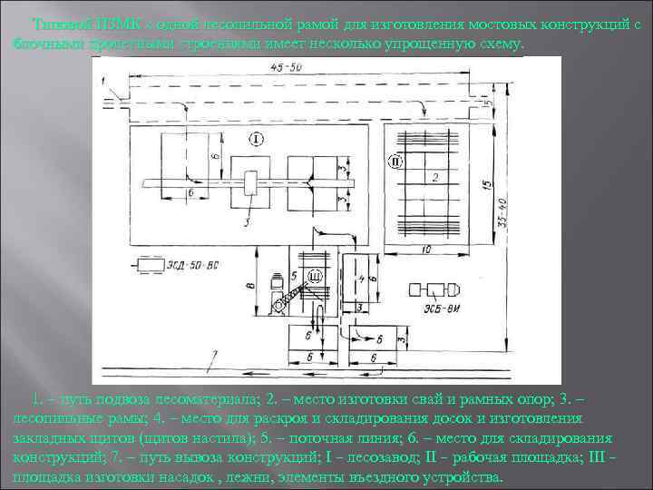 A typical PZMK with one saw frame for the manufacture of bridge structures with block spans has a somewhat simplified design. 1. – route for transporting timber; 2. – place of production of piles and frame supports; 3. – sawmill frames; 4. – a place for cutting and storing boards and making embedded panels (flooring panels); 5. – production line; 6. – space for storing structures; 7. – route for removal of structures; I – sawmill; II – working platform; III – area for manufacturing nozzles, beds, elements of the entry device.
 When manufacturing bridge structures with spans from individual elements, a standard PZMK with one sawmill frame can be deployed 1. a route for transporting timber; 2. cross-cutting platform; 3. sawmill frame; 4. route for removal of finished structures; I. work site for the production of piles and frame supports; II. work site for the production of wheel guard purlins; III. sawmill; IV. working area for the production of nozzles, lower elements of entry devices.
 The third question is “The site for the production of elements of low-water wooden bridges, piles, nozzles, blocks of purlins, diagonal scrums, elements of coastal supports and roadways, production lines for the production of blocks of wooden spans.” The site for the production of elements includes: a place for the production of roadway panels (worker’s boards) flooring, protective flooring boards, wheel guards); place of manufacture of contractions of supports and blocks of spans; place of manufacture of structures (blocks of purlins and roadway panels); place of manufacture of frame supports (racks, bed attachments, lining panels); place of manufacture of elements for the entrance to the bridge, fence wall piles, fence wall boards, boards for the entrance shield, thrust logs, backing logs, gouges.

 When the construction of a bridge is planned to be carried out sequentially, starting with the coastal spans, it is more convenient to place the support elements on the shore, and the elements of the span structures (for example, purlins, cross members, decking and railings) along the road. This arrangement shortens the path for supplying elements to their installation site. Piles are made manually or using a pile preparation machine (PBM). When making piles, a rack is manually installed, which consists of two piles laid on transverse logs or beams, which, in turn, are laid on pads. The elements of such a rack are fastened with pins. The height of the rack is 60-70 cm, length 9-11 m. Notches are made in the beds for a fixed, stable position of the logs during their processing. The head of the pile is processed onto a cylinder. For processing, the pile is placed in nests cut out in the beds and markings are made according to the templates available in the diesel hammer kits. The head of the pile is processed using a special chisel; its use allows you to remove wood on a quarter of the circumference in one go. Pre-cuts are made around the circumference of the pile, which makes processing easier. When processing the head of a pile, it is necessary to ensure the alignment of the head and the entire pile. The end surface is processed perpendicular to the axis of the pile.
 The end of the pile is made with four edges. First, logs are hewn on both sides to a length equal to 2 2.5 diameters so that the tip of the pile is on its axis. Then turn the pile 180° and hew the remaining two sides. When heaving, the wood of the tip is cut; this facilitates the work and protects the pile from unnecessary cutting of wood. The sharp end of the pile is cut off to a length equal to 1/3 of its diameter and then processed into a quadrangular pyramid with a height equal to 1/6 of the pile’s diameter. The manufacture of nozzles and bed supports is carried out on a working platform equipped with horizontal beds. The nozzles of pile supports, as well as the nozzles and beds of frame supports, are made from logs whose diameter is 2 cm larger than the diameter of the piles (racks). The beds provide places for storing logs (blanks), making attachments and beds, as well as for storing finished elements. Double-edged beams are transported from the storage site to the manufacturing site. Then the length and position of the holes for the pins are marked according to the template. The template is made from an edged board with a cross-section of 2.5 x 15 cm and a length equal to the length of the nozzle or bed. After marking the timber, one calculation number files the ends with an electric saw, and the second one drills 3 holes. The manufactured nozzle (bed) is moved along the beds to the storage location. Complete assembly of frame supports is carried out at the PZMK only if the height of the supports allows them to be transported in finished form and there is accurate data on the depth of water at the location where the support is installed on the obstacle. When the height of the supports is high, when transportation of them in assembled form is impossible, the frame supports are pre-assembled at the PZMK, with the fitting of the elements and their markings.
 The fourth question is “Transportation of low-water bridge structures. Calculation of vehicle needs” Transportation of bridge structures from the PZMK to the bridge construction site is carried out by cars, and in some cases using helicopters. To transport bridge structures, any vehicles with a carrying capacity of at least 2, 5, 3 tons are used without additional equipment or with the simplest equipment manufactured by the bridge construction department. The length of blocks or bridge elements transported on cargo platforms of ZIL 131 type vehicles should not exceed 5.5 m, and when transported on Kr type vehicles. AZ 6.5 m. Elements and blocks of bridges with a length of 5.5 to 6.5 m can be transported on ZIL 131 type vehicles equipped with trestles that allow the elements of bridge structures to be positioned with the front ends overhanging the vehicle cabin. To transport elements and blocks longer than 6.5 m, vehicles with trailers are used. This method of transportation is the most preferable, since a trailer increases the vehicle's carrying capacity and increases the amount of cargo transported in one vehicle trip. When transporting track blocks on ZIL 131 type vehicles, two track blocks are placed one on top of the other on the loading platform. One mortgage and one inter-track board each are pre-laid onto the blocks and secured with mounting nails. Span structures from blocks of purlins up to 5 m long and roadway panels
 placed on the car platform in the following order: first, roadway panels are laid one on top of the other, and purlin blocks are placed on top. Depending on the carrying capacity of the vehicles used for transportation, from 4 to 6 sets of pile support elements are loaded onto one vehicle. In this case, the following order of laying elements on a car without a trailer is adopted. In the bottom row there are shorter piles, and longer ones on them; Nozzles and diagonal screeches are placed on top of the piles. When transporting support elements on vehicles with trailers, longer piles are placed in the bottom row, and shorter ones are placed on them; attachments and clamps are placed on top of the piles above the vehicle platform. Loading of blocks and bridge elements onto vehicles and unloading them from vehicles is carried out using truck cranes, cargo booms installed on vehicles with winches, and other lifting means. To load and unload individual elements, they are combined into packages, and each package must consist of elements of the same name (purlins or flooring boards). The number of elements in the package is determined by the lifting capacity of the lifting equipment used. When loading and unloading blocks and packages with a truck crane or a boom mounted on a vehicle, special gripping cable devices “spiders” are used. The gripping cable device consists of 2 or 4 sections of cables with 4 hooks at the ends; all sections of cables with the other end are attached to one end. The “spider” cable gripper is placed in a ring onto the hook of the crane (boom), and the free ends of the cables are secured to blocks or packages of elements. To secure the “spider” hooks on the blocks, special loops (brackets) are installed or the cables are put on the free ends of the purlins. When transporting blocks and individual girders with a length of more than 6.5 m, vehicles with single-axle or two-axle trailers are used. Single axle trailers
 provide transportation of elements up to 10-12 m and a total weight of up to 6-8 tons. Biaxial trailers allow the transportation of elements up to 14-15 m long and a total weight of up to 15 tons. To ensure normal movement on turns, vehicles with trailers are equipped with turning devices, bunks installed on the platform car. In order to successfully complete the construction of a bridge in the shortest possible time, it is necessary to carefully consider the organization of work, i.e., determine how the work should be carried out within the given time frame. The success of construction as a whole will depend on how well the organization of work is thought out. To properly organize the work, it is necessary to determine the need for people, building materials, transport, equipment and mechanisms; The calculation of the specified forces and means is carried out on the basis of the technical design. In cases where the technical design has not yet been drawn up, calculations can be made approximately using enlarged measurements (for example, for 1 linear meter of a bridge), knowing the approximate size and nature of the structure and using standard data from reference books or special tables. The required number of people, building materials, mechanisms and equipment for known volumes of work can also be determined from the collections of Unified Production Standards for bridge construction work.