A. S. Isserlin
The combustion process is based on chemical reactions connection of fuel with oxidizer. For the gas combustion process to occur, special conditions must be created. Firstly, it is necessary to supply a sufficient amount of an oxidizing agent (usually air) to the flammable gas and mix them. Secondly, the gas-air mixture must have concentration limits flammability and an ignition source must be provided. Thirdly, it is necessary to create conditions for the development of the combustion process, i.e. a certain temperature level.
Mixture formation (uniform mixing of gas with air) is one of the main stages of the entire combustion process. All further stages through which the fuel passes when converting chemical energy into thermal energy largely depend on the mixture formation process. Since a high temperature level is always established in the combustion zone, the time spent on chemical combustion reactions is always significantly less than the time required for the mixture formation process.
Burning gas fuel, like any other, in air flow in accordance with modern views, it is possible on the basis of kinetic and diffusion principles.
The total combustion time of the gas, which determines the combustion rate,
TP TS~1"~X1
Where tc is the mixture formation time required to mix the gas with the oxidizer; tx - time of chemical reactions.
If the vehicle<Стх, то практически тп«т*. В этом случае процесс протекает в кинетической области. Если же, наоборот, Тс^-Тх, то Тп»тс и, следовательно, процесс протекает в диффузионной области.
When the combustion process occurs in the kinetic region, the combustion rate depends on the properties of a given combustible mixture, the temperature in the reaction volume and the concentration of reagents in the combustion zone, i.e. it is regulated by the laws of chemical kinetics. At the same time, the rate of the process in the kinetic region does not depend on hydrodynamic factors, i.e., on the flow rate, geometric dimensions of the reaction chamber, etc.
On the contrary, in the diffusion region, the rate of the process is determined by hydrodynamic factors and does not depend on kinetic ones. In this area, the properties of the combustible mixture and the temperature factor cease to play a decisive role. Relatively simple hydrodynamic means can be used to influence the intensity of mixing, which will lead to a change in the characteristics of the diffusion plume.
With the kinetic principle, a homogeneous gas-air mixture is first created in the burner, which is fed into the combustion chamber. Therefore, the combustion of such a mixture occurs at a constant value of all the main characteristics (thermal voltage, excess air, etc.). Purely kinetic combustion occurs only if the condition is met A^1.0. When a<1 кинетическое горение протекает лишь на первой стадии, т. е. до тех пор, пока не израсходован весь кислород смеси. Остаток горючих компонентов, разбавленных продуктами сгорания, может быть сожжен только при условии подвода дополнительного окислителя (воздуха).
The diffusion principle of combustion implies the creation of such conditions for the occurrence of a process under which the mixture burns immediately at its very occurrence, i.e., when the fuel and oxidizer come into contact in appropriate quantitative ratios. The process of diffusion combustion is regulated by changing the intensity of mixture formation by varying the design and operating parameters of the burner. As a result, depending on the technological requirements, it is possible to shorten or lengthen the mixing zone.
In practice, gas combustion is often used, combining both of these principles. In this case, part of the air is pre-mixed with the gas in the burner, and the rest, necessary for complete combustion, is supplied directly to the combustion zone. By changing this ratio, you can influence the length of the gas torch. In most burners, gas is supplied at one angle or another to the air flow.
Many works have been devoted to the study of the mixture formation process. This allows us to formulate some general patterns.
For direct-flow gas burners, the better the mixing, the larger the cross-section of the burner the gas jets cover, i.e., the greater the range of the gas jets. In burners with highly swirling flows, one should not strive for a long range of gas jets.
An increase in the air flow twist leads to a redistribution of gas and air across the burner cross-section, an increase in the intensity of gas-air mixing and an increase in the central zone of reverse currents in the burner.
The nature of the influence of air flow twist on the mixture formation process is different depending on other determining parameters. Thus, when gas is supplied to the peripheral zones of the burner (regardless of its type), an increase in the flow twist leads to a noticeable improvement in mixture formation. On the contrary, when gas is supplied to the central zone of the burner, an increase in twist does not, as a rule, lead to an improvement in the process.
The set of phenomena that we call combustion can only occur in a certain sequence, from one stage to another. G. F. Knorre gives the following diagrams of the steady-state combustion process of gas and liquid fuels with a fixed source, which he calls in-line (Fig. 1). The simplest flow diagram arises when burning gas fuel consisting of simple molecules (for example, hydrogen) that do not require preliminary complex pyrogenic decomposition (Fig. 1, A). When gas or liquid hydrocarbon fuels are burned, A 6
The continuous combustion process becomes more complicated: another intermediate stage occurs - pyrogenic decomposition. For liquid fuel, this stage is preceded by an evaporation stage (Fig. 1.6). To implement a flow scheme, a sufficient temperature level is required in the combustion chamber, to which fuel and oxidizer are supplied in continuous streams. After completion of the reactions, combustion products are also continuously removed from the combustion site.
It is known that gas-air mixtures ignite only when the gas content in the air is within certain (for each gas) limits. At low gas contents, the amount of heat released during combustion is not enough to bring adjacent layers of the mixture to the ignition temperature. The same is observed when the gas content in the gas-air mixture is too high. The lack of oxygen in the air used for combustion leads to a decrease in the temperature level, as a result of which the adjacent layers of the mixture do not heat up to
Ignition temperatures. These two cases correspond to the lower and upper flammability limits (Table 1). Therefore, in addition to mixing gas with air in certain proportions, initial conditions must be created for the ignition of the mixture.
|
Table / Flammability limits and ignition temperatures of various gases in air
|
Oxidation of flammable gases is possible at low temperatures, but then it proceeds extremely slowly due to the low reaction rate. As the temperature increases, the rate of the oxidation reaction increases until spontaneous combustion occurs (instead of slow oxidation, the process of spontaneous combustion begins). This means that a combustible mixture heated to the ignition temperature has such energy that it not only compensates for heat loss to the environment, but also ensures heating and preparation of the gas-air mixture entering the combustion zone for ignition.
The ignition temperature of a gas depends on a number of factors, including the content of flammable gas in the gas-air mixture, pressure, method of heating the mixture, etc., and therefore is not an exact value. In table Table 1 shows the ignition temperatures of some flammable gases in the air.
In practice, there are two methods of igniting flammable mixtures: self-ignition and ignition.
At Self-ignition the entire volume of the combustible gas-air mixture is gradually brought to the ignition temperature, after which the mixture ignites without external thermal influence.
The second method, called Ignition. With this method, it is not necessary to heat the entire gas-air mixture to the ignition temperature; it is enough to ignite the cold mixture at one point in the volume with some high-temperature source (spark, hot body, pilot flame, etc.). As a result, ignition is transmitted to the entire volume of the mixture spontaneously through the spread of flame, which does not occur instantly, but at a certain spatial speed. This speed is called Flame propagation speed in a gas-air mixture and is the most important characteristic that determines the conditions for the occurrence and stabilization of combustion. The stability of the burners, as will be shown below, is related to the speed of flame propagation.
Thus, the combustion process of gas fuel consists of mixing gas with air, heating the resulting mixture to the ignition temperature, igniting it and the occurrence of combustion reactions, accompanied by the release of heat. Moreover, mixing gas with air and heating the mixture takes up most of the time during the combustion process, since combustion reactions occur almost instantly.
Depending on the technological process (production of steam and hot water in a boiler unit, heating of products in a furnace unit, etc.), it becomes necessary to influence the combustion process, changing its final characteristics. This is achieved by various design techniques, which are outlined in Chapter. III.
A comparison of temperature fields in the volume of a torch during gas combustion with different excess air ratios is indicative. An example of such a comparison is given in Fig. 2 for a burner with an outlet nozzle diameter of 35 mm as a function
|
|
Where AND- current temperature value in the flame, °C; £max - maximum temperature in the flame (measured), °C; X- distance from the measurement point to the beginning of the torch, m; U- distance from the measuring point to the torch axis, m; Y- burner nozzle diameter, m.
In Fig. Figure 2 shows temperature distribution graphs for three excess air coefficients. Moreover, the coordinate X/y=O corresponds to the exit section of the burner nozzle, and the coordinate U/y=0 - torch axis.
As can be seen from the figure, the temperature distribution in the free plume is uneven. At small excesses of primary air, for example a = 0.5, the presence of an internal core in the plume greatly distorts the temperature field and it levels out only at a distance x/c/ = 10, while at a = 0.75 leveling occurs already at X/y=2.5, and at a=1.0 even earlier - at X/y=1.0.
The highest temperatures in open flames are observed in the initial sections at a distance from the flame axis U/y = 0.5, and then in the center of the torch. Moreover, with an increase in the excess air coefficient, the maximum temperature shifts towards the burner mouth. Thus, the highest temperature at a = 0.75 was measured at a distance X/y=2.5, and at a =1.0 - at a distance X/y=1.0.
 When considering the distribution of temperatures and CO2 concentrations in the plume together, a coincidence of maxima is observed
Temperatures and CO2 contents. Consequently, the maximum temperature level in the flame corresponds to the maximum degree of combustion of combustibles.
The loss of some of the heat released as a result of gas combustion is inevitable. However, they can be reduced to a minimum with proper combustion process management. Let's consider which ones. components add up these losses.
When burning gas fuel, the following heat losses occur: with exhaust gases, from chemical incomplete combustion and into the environment. Based on the determination of individual heat losses by reverse balance, the efficiency (efficiency) of the unit, °/o, can be calculated:
Where<72 - потери тепла с уходящими газами, %; - потери тепла
From chemical incompleteness of combustion, %; Q5- heat loss to the environment, %.
Heat loss with flue gases- physical heat of combustion products leaving the unit is the main one. It is impossible to completely eliminate them, but it is necessary to strive to reduce them. Heat losses with flue gases depend on the temperature of the gases and their quantity. The lower the flue gas temperature, the less heat will be lost, so you should strive to reduce the flue gas temperature within reasonable limits. The influence of flue gas temperature on heat loss can be seen from Table. 2.
table 2
|
Heat loss from flue gases during combustion natural gas, %
|
Heat loss with exhaust gases is usually expressed as a percentage of the total available heat, i.e., the heat of combustion of the fuel. For example, if the heat loss is 700 kcal/m3 when burning natural gas, then
700-100 ___ „ 24°/
The amount of gases leaving the unit depends on the excess air coefficient with which the burner operates and the suction
Air through leaks in the unit. The greater the coefficient of excess air at the outlet of the burner and air suction into the unit, the higher the heat loss with the flue gases. From the table 2 shows that a change in the total coefficient of excess air in the combustion products with aa = 1.2-5-1.6 increases the heat loss with the flue gases from 10.5 to 13.2% (at a constant flue gas temperature of 240 ° C).
Thus, to reduce heat loss with flue gases, it is necessary to conduct the combustion process with the lowest permissible excess air ratio, ensure the highest density of the unit and achieve a reduction in the temperature of the flue gases.
Heat losses from chemical incomplete combustion of gas occur when there is a lack of air, poor mixing in the gas burner, or a sharp decrease in the temperature level in the combustion zone. As a result, gas combustion occurs incompletely and flammable components (for example, hydrogen, carbon monoxide, etc.) leave with the combustion products. This leads to underutilization of the chemical energy of the fuel and a decrease in the efficiency of the unit. Even a small content of flammable components in combustion products leads to significant heat losses from chemical incomplete combustion. Let's assume that the combustion products contained 0.7% hydrogen and 0.5% carbon monoxide. The unit burned natural gas with a coefficient of excess air behind the installation a» = = 1.5. Heat loss from chemical incomplete combustion amounted to ~450 kcal/m3 or
A___ 450-100 poo/
Thus, from the considered example it is clear that combustible components in combustion products must be completely absent or be of a minimum value.
Heat loss to the environment is due to the fact that the walls of the unit have a higher temperature than the surrounding air. The magnitude of these losses depends mainly on the temperature difference between the outer walls of the unit and the surrounding air, the size of the wall surface, the thermal conductivity of the masonry material and its thickness. Losses to the environment are calculated theoretically or taken from thermal calculation standards, depending on the design and performance of the unit.
If we sum up all the heat losses that occur when burning gas in a unit and subtract them from 100, we will obtain the efficiency of the unit. For example, let's use the figures given above, taking<75 равным 3,60%, тогда к. п. д. агрегата
T]= 100-(8.24+5.28+3.60)=82.88%*
8.1. COMBUSTION REACTIONS
Combustion is a fast-flowing chemical reaction of combining combustible components with oxygen, accompanied by intense heat release and a sharp increase in the temperature of combustion products. Combustion reactions are described by the so-called. stoichiometric equations characterizing qualitatively and quantitatively the substances that react and are formed as a result of the reaction (The stoichiometric composition of a combustible mixture (from the Greek stoicheion - base, element and Greek metreo - measure) - the composition of a mixture in which there is exactly as much oxidizer as is necessary for complete oxidation of the fuel). The general equation for the combustion reaction of any hydrocarbon
C m H n + (m + n/4) O 2 = mCO 2 + (n/2) H 2 O + Q(8.1)
where m, n is the number of carbon and hydrogen atoms in the molecule; Q is the thermal effect of the reaction, or heat of combustion.
The combustion reactions of some gases are given in table. 8.1. These equations are balance equations, and they cannot be used to judge either the rate of reactions or the mechanism of chemical transformations.
Table 8.1. Combustion reactions and heat of combustion of dry gases (at 0°C and 101.3 kPa)
| Gas | Combustion reaction | Heat of combustion | |||||
|---|---|---|---|---|---|---|---|
| Molar, kJ/kmol | Mass, kJ/kg | Volume, kJ/m 3 | |||||
| highest | lowest | highest | lowest | highest | lowest | ||
| Hydrogen | H 2 + 0.5O 2 = H 2 0 | 286,06 | 242,90 | 141 900 | 120 080 | 12 750 | 10 790 |
| Carbon monoxide | CO + 0.5O 2 = CO 2 | 283,17 | 283,17 | 10 090 | 10 090 | 12 640 | 12 640 |
| Methane | CH 4 + 2O 2 = CO 2 + 2H 2 O | 880,90 | 800,90 | 55 546 | 49 933 | 39 820 | 35 880 |
| Ethane | C 2 H 6 + 0.5O 2 = 2CO 2 + 3H 2 O | 1560,90 | 1425,70 | 52 019 | 47 415 | 70 310 | 64 360 |
| Propane | C 3 H 8 + 5H 2 O = 3CO 2 + 4H 2 O | 2221,40 | 2041,40 | 50 385 | 46 302 | 101 210 | 93 180 |
| n-butane | 2880,40 | 2655,00 | 51 344 | 47 327 | 133 800 | 123 570 | |
| Isobutane | C 4 H 10 + 6.5O 2 = 4CO 2 + 5H 2 O | 2873,50 | 2648,30 | 51 222 | 47 208 | 132 960 | 122 780 |
| n-Pentane | C5H12 + 8O2 = 5CO2 + 6H2O | 3539,10 | 3274,40 | 49 052 | 45 383 | 169 270 | 156 630 |
| Ethylene | C 2 H 4 + 3O 2 = 2CO 2 + 2H 2 O | 1412,00 | 1333,50 | 50 341 | 47 540 | 63 039 | 59 532 |
| Propylene | C 3 H 6 + 4.5O 2 = 3CO 2 + 3H 2 O | 2059,50 | 1937,40 | 48 944 | 46 042 | 91 945 | 88 493 |
| Butylene | C 4 H 8 + 6O 2 = 4CO 2 + 4H 2 O | 2720,00 | 2549,70 | 48 487 | 45 450 | 121 434 | 113 830 |
Thermal effect (heat of combustion) Q is the amount of heat released during complete combustion of 1 kmol, 1 kg or 1 m 3 of gas under normal physical conditions. A distinction is made between higher Q in and lower Q n heat of combustion: the higher heat of combustion includes the heat of condensation of water vapor during the combustion process (in reality, when burning gas, water vapor is not condensed, but is removed along with other combustion products). Typically, technical calculations are usually carried out based on the lower calorific value, without taking into account the heat of condensation of water vapor (≈2400 kJ/kg).
The efficiency calculated based on the lower calorific value is formally higher, but the heat of condensation of water vapor is quite high, and its use is more than advisable. This is confirmed by the active use of contact heat exchangers in heating technology, which are very diverse in design.
For a mixture of combustible gases, the higher (and lower) heat of combustion of gases is determined by the relation
Q = r 1 Q 1 + r 2 Q 2 + ... + r n Q n (8.2)
where r 1, r 2, …, r n are the volume (molar, mass) fractions of the components included in the mixture; Q 1, Q 2, …, Q n - heat of combustion of components.
Using the table. 8.1, the higher and lower heat of combustion, kJ/m 3, of a complex gas can be determined using the following formulas:
Q in = 127.5 H 2 + 126.4 CO + 398 CH 4 + 703 C 2 H 6 + 1012 C 8 H 8 + 1338 C 4 H 10 + 1329 C 4 H 10 +
+ 1693 C 5 H 12 + 630 C 2 H 4 + 919 C 3 H 6 +1214 C 4 H 8 (8.3)
Qn = 107.9 H 2 + 126.4 CO + 358.8 CH 4 + 643 C 2 H 6 + 931.8 C 8 H 8 + 1235 C 4 H 10 + 1227 C 4 H 10 +
+ 1566 C 5 H 12 + 595 C 2 H 4 + 884 C 8 H 6 + 1138 C 4 H 8 (8.4)
where H 2, CO, CH 4, etc. - content of individual components in gas fuel, vol. %.
The combustion process is much more complicated than according to formula (8.1), since along with branching of chains, they are broken due to the formation of intermediate stable compounds, which undergo further transformations at high temperatures. With a sufficient oxygen concentration, the final products are formed: water vapor H 2 O and carbon dioxide CO 2. If there is a lack of oxidizing agent, as well as when the reaction zone is cooled, intermediate compounds can stabilize and enter the environment.
The intensity of heat generation and an increase in temperature lead to an increase in active particles in the reacting system. This relationship between the chain reaction and temperature, characteristic of almost all combustion processes, led to the introduction of the concept of a chain-thermal explosion - the chemical combustion reactions themselves are of a chain nature, and their acceleration occurs due to the release of heat and an increase in temperature in the reacting system.
The rate of a chemical reaction in a homogeneous mixture is proportional to the product of the concentrations of the reacting substances:
w = kС 1 С 2 (8.5)
where C1 and C2 are the concentrations of the reacting components, kmol/m3; k is the reaction rate constant, depending on the nature of the reactants and temperature.
When burning gas, the concentrations of reacting substances can be conditionally considered unchanged, since in the combustion zone there is a continuous influx of fresh components of unambiguous composition.
Reaction rate constant (according to the Arrhenius equation):
K = K 0 e -E/RT (8.6)
where K 0 is the pre-exponential factor adopted for biometric homogeneous mixtures, ≈1.0; E - activation energy, kJ/kmol; R - universal gas constant, J/(kg K); T - absolute temperature, K (°C); e is the base of natural logarithms.
The pre-exponential factor K 0 can be interpreted as a constant reflecting the completeness of the collision of molecules, and E as the minimum energy for breaking the bonds of molecules and the formation of active particles that ensure the efficiency of collisions. For common flammable mixtures, it falls within the range of (80÷150) 10 3 kJ/kmol.
Equation (8.6) shows that the rate of chemical reactions increases sharply with increasing temperature: for example, an increase in temperature from 500 to 1000 K entails an increase in the rate of combustion reaction by 2 10 4 ÷ 5 10 8 times (depending on the activation energy).
The rate of combustion reactions is affected by their chain nature. Initially generated by the reaction, atoms and radicals enter into compounds with the original substances and with each other, forming final products and new particles that repeat the same chain of reactions. The increasing generation of such particles leads to the “acceleration” of chemical reactions - in fact, the explosion of the entire mixture.
High-temperature combustion of hydrocarbons is complex and is associated with the formation of active particles in the form of atoms and radicals, as well as intermediate molecular compounds. As an example, the combustion reactions of the simplest hydrocarbon - methane are given:
- H + O 2 -› OH + O
CH 4 + OH -› CH 3 + H 2 O
CH 4 + O -› CH 2 + H 2 O - CH 3 + O 2 -› HCHO + OH
CH 2 + O 2 -› HCHO + O - HCHO + OH -› HCO + H 2 O
HCNO + O -› CO + H 2 O
HCO + O 2 -› CO + O + OH - CO + O -› CO 2
CO + OH -› CO 2 + H
Summary of a single cycle:
2CH 4 + 4O 2 -› 2CO 2 + 4H 2 O
8.2. COMBUSTION CALCULATIONS
Oxygen for combustion comes from the air as its component. For calculations, it is assumed that the volumetric composition of dry air is as follows:
oxygen - 21.0%, nitrogen - 79.0%.
According to the information provided, 1 m 3 of oxygen is contained in 100/21 = 4.76 m 3 of air, or 1 m 3 of oxygen contains 79/21 = 3.76 m 3 of nitrogen. Considering that 1 kmol of gas under normal conditions occupies a volume of 22.4 liters, the combustion reaction (see equation 8.1) of any hydrocarbon in air can be written in a general form:
C m H n + (t + n/4) (O 2 + 3.76N 2) = tCO 2 + (n/2) H 2 O + (t +n/4) 3.76N 2
The requirements for oxygen and air during the combustion of various gases, calculated from the given combustion reactions, are presented in Table. 8.2.
Table 8.2. Theoretical need for dry oxygen and air, m3, and the volume of gas combustion products when burning 1 m3 of gas
| Gas | Theoretical need | Combustion products | ||||
|---|---|---|---|---|---|---|
| oxygen | air | carbon dioxide | water vapor | nitrogen | Total | |
| Hydrogen H2 | 0,5 | 2,38 | – | 1,0 | 1,88 | 2,88 |
| Carbon monoxide CO | 0,5 | 2,38 | 1,0 | – | 1,88 | 2,88 |
| Methane CH 4 | 2,0 | 9,52 | 1,0 | 2,0 | 7,52 | 10,52 |
| Ethane C2H6 | 3,5 | 16,66 | 2,0 | 3,0 | 13,16 | 18,16 |
| Propane C 3 H 8 | 5,0 | 23,80 | 3,0 | 4,0 | 18,80 | 25,80 |
| Butane C4H10 | 6,5 | 30,94 | 4,0 | 5,0 | 24,44 | 33,44 |
| Pentane C5H12 | 8,0 | 38,08 | 5,0 | 6,0 | 30,08 | 41,08 |
| Ethylene C2H4 | 3,0 | 14,28 | 2,0 | 2,0 | 11,28 | 15,28 |
| Propylene C3H6 | 4,5 | 21,42 | 3,0 | 3,0 | 16,92 | 22,92 |
| Butylene C4H8 | 6,0 | 28,56 | 4,0 | 4,0 | 22,56 | 30,56 |
| Pentylene C 5 H 10 | 7,5 | 35,70 | 5,0 | 5,0 | 28,20 | 38,20 |
| Acetylene C 2 H 2 | 2,5 | 11,90 | 2,0 | 1,0 | 9,40 | 12,40 |
For a complex gas, dry air consumption Vc, m3/m3, is calculated using a formula that takes into account the oxygen demand of individual components of the mixture:
V c =4.76/100 (0.5H 2 +0.5CO+2CH 4 +3.5C 2 H 6 +5C 3 H 8 +6.5C 4 H 10 +3C 2 H 4 +4.5C 3 H 6 +6C 4 H 8 -O 2 (8.7)
Theoretical flow rate of moist air Vl, m 3 / m 3, greater than that determined by formula (8.7) for the volume of contained water vapor:
Vvl = Vs + 0.001244d in Vs (8.8)
where d in - air humidity, g/m 3.
With an unknown chemical composition of gases, but a known lower calorific value Q n, kJ/m 3, theoretical air flow V t, m 3 / m 3,
V t ≈ Q n /3770(8.9)
The actual air flow rate V dv, m 3 / m 3, is always assumed to be somewhat larger:
V dv = V t α(8.10)
where α is the excess air coefficient corresponding to GOST requirements. For complete combustion of fuel, the value of α must be greater than 1. The composition and volume of combustion products, calculated from the combustion reactions of certain gases in dry air, are given in Table. 8.2.
8.3. BURNING TEMPERATURE
In heat engineering, the following combustion temperatures of gases are distinguished: heat output, calorimetric, theoretical and real (calculated). Heat output tf - maximum temperature of the products of complete combustion of gas under adiabatic conditions with an excess air coefficient α = 1.0 and at a gas and air temperature of 0°C:
t f = Q n /(∑Vc p)(8.11)
where Qn is the lower heat of combustion of gas, kJ/m 3 ; ∑Vc p - the sum of the products of the volumes of carbon dioxide, water vapor and nitrogen formed during the combustion of 1 m 3 of gas (m 3 / m 3), and their average volumetric heat capacities at constant pressure within the temperature range from 0 ° C to t l (kJ /(m 3 o°C).
Due to the variability of the heat capacity of gases, the heat output is determined by the method of successive approximations. Its value for natural gas (≈2000°C) is taken as the initial parameter; at α = 1.0, the volumes of components of combustion products are determined according to table. 8.3 their average heat capacity is found and then the heat capacity of the gas is calculated using formula (8.11). If, as a result of the calculation, it turns out to be lower or higher than the accepted one, then another temperature is set and the calculation is repeated.
Table 8.3. Average volumetric heat capacity of gases, kJ/(m 3 °C)
Temperature, °C |
CO2 | N 2 | O2 | CO | CH 4 | H 2 | H 2 O (water vapor) | air | |
|---|---|---|---|---|---|---|---|---|---|
| dry | wet per 1 m 3 dry gas |
||||||||
| 0 | 1,5981 | 1,2970 | 1,3087 | 1,3062 | 1,5708 | 1,2852 | 1,4990 | 1,2991 | 1,3230 |
| 100 | 1,7186 | 1,2991 | 1,3209 | 1,3062 | 1,6590 | 1,2978 | 1,5103 | 1,3045 | 1,3285 |
| 200 | 1,8018 | 1,3045 | 1,3398 | 1,3146 | 1,7724 | 1,3020 | 1,5267 | 1,3142 | 1,3360 |
| 300 | 1,8770 | 1,3112 | 1,3608 | 1,3230 | 1,8984 | 1,3062 | 1,5473 | 1,3217 | 1,3465 |
| 400 | 1,9858 | 1,3213 | 1,3822 | 1,3356 | 2,0286 | 1,3104 | 1,5704 | 1,3335 | 1,3587 |
| 500 | 2,0030 | 1,3327 | 1,4024 | 1,3482 | 2,1504 | 1,3104 | 1,5943 | 1,3469 | 1,3787 |
| 600 | 2,0559 | 1,3453 | 1,4217 | 1,3650 | 2,2764 | 1,3146 | 1,6195 | 1,3612 | 1,3873 |
| 700 | 2,1034 | 1,3587 | 1,3549 | 1,3776 | 2,3898 | 1,3188 | 1,6464 | 1,3755 | 1,4020 |
| 800 | 2,1462 | 1,3717 | 1,4549 | 1,3944 | 2,5032 | 1,3230 | 1,6737 | 1,3889 | 1,4158 |
| 900 | 2,1857 | 1,3857 | 1,4692 | 1,4070 | 2,6040 | 1,3314 | 1,7010 | 1,4020 | 1,4293 |
| 1000 | 2,2210 | 1,3965 | 1,4822 | 1,4196 | 2,7048 | 1,3356 | 1,7283 | 1,4141 | 1,4419 |
| 1100 | 2,2525 | 1,4087 | 1,4902 | 1,4322 | 2,7930 | 1,3398 | 1,7556 | 1,4263 | 1,4545 |
| 1200 | 2,2819 | 1,4196 | 1,5063 | 1,4448 | 2,8812 | 1,3482 | 1,7825 | 1,4372 | 1,4658 |
| 1300 | 2,3079 | 1,4305 | 1,5154 | 1,4532 | – | 1,3566 | 1,8085 | 1,4482 | 1,4771 |
| 1400 | 2,3323 | 1,4406 | 1,5250 | 1,4658 | – | 1,3650 | 1,8341 | 1,4582 | 1,4876 |
| 1500 | 2,3545 | 1,4503 | 1,5343 | 1,4742 | – | 1,3818 | 1,8585 | 1,4675 | 1,4973 |
| 1600 | 2,3751 | 1,4587 | 1,5427 | – | – | – | 1,8824 | 1,4763 | 1,5065 |
| 1700 | 2,3944 | 1,4671 | 1,5511 | – | – | – | 1,9055 | 1,4843 | 1,5149 |
| 1800 | 2,4125 | 1,4746 | 1,5590 | – | – | – | 1,9278 | 1,4918 | 1,5225 |
| 1900 | 2,4289 | 1,4822 | 1,5666 | – | – | – | 1,9698 | 1,4994 | 1,5305 |
| 2000 | 2,4494 | 1,4889 | 1,5737 | 1,5078 | – | – | 1,9694 | 1,5376 | 1,5376 |
| 2100 | 2,4591 | 1,4952 | 1,5809 | – | – | – | 1,9891 | – | – |
| 2200 | 2,4725 | 1,5011 | 1,5943 | – | – | – | 2,0252 | – | – |
| 2300 | 2,4860 | 1,5070 | 1,5943 | – | – | – | 2,0252 | – | – |
| 2400 | 2,4977 | 1,5166 | 1,6002 | – | – | – | 2,0389 | – | – |
| 2500 | 2,5091 | 1,5175 | 1,6045 | – | – | – | 2,0593 | – | – |
The heat output of common simple and complex gases when they burn in dry air is given in Table. 8.4. When burning gas in atmospheric air containing about 1 wt. % moisture, heat output decreases by 25–30°C.
Table 8.4. Heat capacity of gases in dry air
| Simple gas | Heat capacity, °C | Complex gas average composition |
Approximate heat output, °C |
|---|---|---|---|
| Hydrogen | 2235 | Natural gas fields |
2040 |
| Carbon monoxide | 2370 | Natural oil fields |
2080 |
| Methane | 2043 | Coke |
2120 |
| Ethane | 2097 | High temperature distillation of shale |
1980 |
| Propane | 2110 | Vapor-oxygen blast under pressure |
2050 |
| Butane | 2118 | Generator made from fat coals |
1750 |
| Pentane | 2119 | Generator steam-air blast from lean fuels |
1670 |
| Ethylene | 2284 | Liquefied (50% C 3 H 4 +50% C 4 H 10) |
2115 |
| Acetylene | 2620 | 2210 |
Calorimetric combustion temperature tk is the temperature determined without taking into account the dissociation of water vapor and carbon dioxide, but taking into account the actual initial temperature of the gas and air. It differs from the heat output tf in that the temperature of the gas and air, as well as the excess air coefficient α, are taken according to their actual values. You can determine tk using the formula:
t k = (Q n + q physical)/(ΣVc p)(8.12)
where q physical is the heat content (physical heat) of gas and air, measured from 0°C, kJ/m 3 .
Natural and liquefied hydrocarbon gases are usually not heated before combustion, and their volume is small compared to the volume of air used for combustion. Therefore, when determining the calorimetric temperature, the heat content of gases can be ignored. When burning gases with a low calorific value (generator gases, blast furnace gases, etc.), their heat content (especially those heated before combustion) has a very significant effect on the calorimetric temperature.
The dependence of the calorimetric temperature of natural gas of average composition in air with a temperature of 0°C and a humidity of 1% on the excess air coefficient α is given in Table. 8.5, for liquefied hydrocarbon gas when burned in dry air - in table. 8.7. Table data 8.5–8.7 can be used with sufficient accuracy to guide the determination of the calorimetric combustion temperature of other natural gases, relatively similar in composition, and hydrocarbon gases of almost any composition. If it is necessary to obtain a high temperature when burning gases with low excess air ratios, as well as to increase the efficiency of furnaces, in practice the air is heated, which leads to an increase in the calorimetric temperature (see Table 8.6).
Table 8.5. Calorimetric and theoretical combustion temperatures of natural gas in air with t = 0°C and humidity 1% depending on the excess air coefficient α
| Theoretical combustion temperature t t, °C | Excess air coefficient α | Calorimetric combustion temperature tc, °C | ||
|---|---|---|---|---|
| 1,0 | 2010 | 1920 | 1,33 | 1620 |
| 1,02 | 1990 | 1900 | 1,36 | 1600 |
| 1,03 | 1970 | 1880 | 1,40 | 1570 |
| 1,05 | 1940 | 1870 | 1,43 | 1540 |
| 1,06 | 1920 | 1860 | 1,46 | 1510 |
| 1,08 | 1900 | 1850 | 1,50 | 1470 |
| 1,10 | 1880 | 1840 | 1,53 | 1440 |
| 1,12 | 1850 | 1820 | 1,57 | 1410 |
| 1,14 | 1820 | 1790 | 1,61 | 1380 |
| 1,16 | 1800 | 1770 | 1,66 | 1350 |
| 1,18 | 1780 | 1760 | 1,71 | 1320 |
| 1,20 | 1760 | 1750 | 1,76 | 1290 |
| 1,22 | 1730 | – | 1,82 | 1260 |
| 1,25 | 1700 | – | 1,87 | 1230 |
| 1,28 | 1670 | – | 1,94 | 1200 |
| 1,30 | 1650 | – | 2,00 | 1170 |
Table 8.6. Calorimetric combustion temperature of natural gas tc, °C, depending on the coefficient of excess dry air and its temperature (rounded values)
| Excess air coefficient α | Dry air temperature, °C | ||||||||
|---|---|---|---|---|---|---|---|---|---|
| 20 | 100 | 200 | 300 | 400 | 500 | 600 | 700 | 800 | |
| 0,5 | 1380 | 1430 | 1500 | 1545 | 1680 | 1680 | 1740 | 1810 | 1860 |
| 0,6 | 1610 | 1650 | 1715 | 1780 | 1840 | 1900 | 1960 | 2015 | 2150 |
| 0,7 | 1730 | 1780 | 1840 | 1915 | 1970 | 2040 | 2100 | 2200 | 2250 |
| 0,8 | 1880 | 1940 | 2010 | 2060 | 2130 | 2200 | 2260 | 2330 | 2390 |
| 0,9 | 1980 | 2030 | 2090 | 2150 | 2220 | 2290 | 2360 | 2420 | 2500 |
| 1,0 | 2050 | 2120 | 2200 | 2250 | 2320 | 2385 | 2450 | 2510 | 2560 |
| 1,2 | 1810 | 1860 | 1930 | 2000 | 2070 | 2140 | 2200 | 2280 | 2350 |
| 1,4 | 1610 | 1660 | 1740 | 1800 | 2870 | 1950 | 2030 | 2100 | 2160 |
| 1,6 | 1450 | 1510 | 1560 | 1640 | 1730 | 1800 | 1860 | 1950 | 2030 |
| 1,8 | 1320 | 1370 | 1460 | 1520 | 1590 | 1670 | 1740 | 1830 | 1920 |
| 2,0 | 1220 | 1270 | 1360 | 1420 | 1490 | 1570 | 1640 | 1720 | 1820 |
Table 8.7. Calorimetric combustion temperature tk of technical propane in dry air with t = 0°C depending on the excess air coefficient α
| Excess air coefficient α | Calorimetric combustion temperature tc, °C | Excess air coefficient α | Calorimetric combustion temperature tc, °C |
|---|---|---|---|
| 1,0 | 2110 | 1,45 | 1580 |
| 1,02 | 2080 | 1,48 | 1560 |
| 1,04 | 2050 | 1,50 | 1540 |
| 1,05 | 2030 | 1,55 | 1500 |
| 1,07 | 2010 | 1,60 | 1470 |
| 1,10 | 1970 | 1,65 | 1430 |
| 1,12 | 1950 | 1,70 | 1390 |
| 1,15 | 1910 | 1,75 | 1360 |
| 1,20 | 1840 | 1,80 | 1340 |
| 1,25 | 1780 | 1,85 | 1300 |
| 1,27 | 1750 | 1,90 | 1270 |
| 1,30 | 1730 | 1,95 | 1240 |
| 1,35 | 1670 | 2,00 | 1210 |
| 1,40 | 1630 | 2,10 | 1170 |
Theoretical combustion temperature t T is the maximum temperature, determined similarly to the calorimetric t k, but adjusted for endothermic (heat-requiring) reactions of dissociation of carbon dioxide and water vapor, which occur with increasing volume:
CO 2 ‹–› CO + 0.5O 2 - 283 mJ/mol (8.13)
H 2 O ‹–› H 2 + 0.5 O 2 - 242 mJ/mol (8.14)
At high temperatures, dissociation can lead to the formation of atomic hydrogen, oxygen and hydroxyl OH groups. In addition, when gas is burned, some amount of nitrogen oxide is always produced. All these reactions are endothermic and lead to a decrease in combustion temperature.
The theoretical combustion temperature can be determined by the following formula:
t T = (Q n + q physical – q dis)/(ΣVc p)(8.15)
where q dis is the total heat consumption for the dissociation of CO 2 and H 2 O in combustion products, kJ/m 3 ; ΣVc p is the sum of the product of the volume and the average heat capacity of combustion products, taking into account dissociation per 1 m 3 of gas.
Table 8.8. The degree of dissociation of water vapor H 2 O and carbon dioxide CO 2 depending on partial pressure
| Temperature, °C | Partial pressure, MPa | |||||||||||
|---|---|---|---|---|---|---|---|---|---|---|---|---|
| 0,004 | 0,006 | 0,008 | 0,010 | 0,012 | 0,014 | 0,016 | 0,018 | 0,020 | 0,025 | 0,030 | 0,040 | |
| Water vapor H2O | ||||||||||||
| 1600 | 0,85 | 0,75 | 0,65 | 0,60 | 0,58 | 0,56 | 0,54 | 0,52 | 0,50 | 0,48 | 0,46 | 0,42 |
| 1700 | 1,45 | 1,27 | 1,16 | 1,08 | 1,02 | 0,95 | 0,90 | 0,85 | 0,8 | 0,76 | 0,73 | 0,67 |
| 1800 | 2,40 | 2,10 | 1,90 | 1,80 | 1,70 | 1,60 | 1,53 | 1,46 | 1,40 | 1,30 | 1,25 | 1,15 |
| 1900 | 4,05 | 3,60 | 3,25 | 3,0 | 2,85 | 2,70 | 2,65 | 2,50 | 2,40 | 2,20 | 2,10 | 1,9 |
| 2000 | 5,75 | 5,05 | 4,60 | 4,30 | 4,0 | 3,80 | 3,55 | 3,50 | 3,40 | 3,15 | 2,95 | 2,65 |
| 2100 | 8,55 | 7,50 | 6,80 | 6,35 | 6,0 | 5,70 | 5,45 | 5,25 | 5,10 | 4,80 | 4,55 | 4,10 |
| 2200 | 12,3 | 10,8 | 9,90 | 9,90 | 8,80 | 8,35 | 7,95 | 7,65 | 7,40 | 6,90 | 6,50 | 5,90 |
| 2300 | 16,0 | 15,0 | 13,7 | 12,9 | 12,2 | 11,6 | 11,1 | 10,7 | 10,4 | 9,6 | 9,1 | 8,4 |
| 2400 | 22,5 | 20,0 | 18,4 | 17,2 | 16,3 | 15,6 | 15,0 | 14,4 | 13,9 | 13,0 | 12,2 | 11,2 |
| 2500 | 28,5 | 25,6 | 23,5 | 22,1 | 20,9 | 20,0 | 19,3 | 18,6 | 18,0 | 16,8 | 15,9 | 14,6 |
| 3000 | 70,6 | 66,7 | 63,8 | 61,6 | 59,6 | 58,0 | 56,5 | 55,4 | 54,3 | 51,9 | 50,0 | 47,0 |
| Carbon dioxide CO2 | ||||||||||||
| 1500 | 0,5 | 0,5 | 0,5 | 0,5 | 0,5 | 0,5 | 0,4 | 0,4 | 0,4 | 0,4 | 0,4 | – |
| 1600 | 2,0 | 1,8 | 1,6 | 1,5 | 1,45 | 1,4 | 1,35 | 1,3 | 1,25 | 1,2 | 1,1 | |
| 1700 | 3,8 | 3,3 | 3,0 | 2,8 | 2,6 | 2,5 | 2,4 | 2,3 | 2,2 | 2,0 | 1,9 | |
| 1800 | 6,3 | 5,5 | 5,0 | 4,6 | 4,4 | 4,2 | 4,0 | 3,8 | 3,7 | 3,5 | 3,3 | |
| 1900 | 10,1 | 8,9 | 8,1 | 7,6 | 7,2 | 6,8 | 6,5 | 6,3 | 6,1 | 5,6 | 5,3 | |
| 2000 | 16,5 | 14,6 | 13,4 | 12,5 | 11,8 | 11,2 | 10,8 | 10,4 | 10,0 | 9,4 | 8,8 | |
| 2100 | 23,9 | 21,3 | 19,6 | 18,3 | 17,3 | 16,5 | 15,9 | 15,3 | 14,9 | 13,9 | 13,1 | |
| 2200 | 35,1 | 31,5 | 29,2 | 27,5 | 26,1 | 25,0 | 24,1 | 23,3 | 22,6 | 21,2 | 20,1 | |
| 2300 | 44,7 | 40,7 | 37,9 | 35,9 | 34,3 | 32,9 | 31,8 | 30,9 | 30,0 | 28,2 | 26,9 | |
| 2400 | 56,0 | 51,8 | 48,8 | 46,5 | 44,6 | 43,1 | 41,8 | 40,6 | 39,6 | 37,5 | 35,8 | |
| 2500 | 66,3 | 62,2 | 59,3 | 56,9 | 55,0 | 53,4 | 52,0 | 50,7 | 49,7 | 47,3 | 45,4 | |
| 3000 | 94,9 | 93,9 | 93,1 | 92,3 | 91,7 | 90,6 | 90,1 | 89,6 | 88,5 | 87,6 | 86,8 | |
As can be seen from table. 8.8, at temperatures up to 1600°C, the degree of dissociation may not be taken into account, and the theoretical combustion temperature may be taken equal to the calorimetric one. At higher temperatures, the degree of dissociation can significantly reduce the temperature in the workspace. In practice, there is no particular need for this; the theoretical combustion temperature needs to be determined only for high-temperature furnaces operating on preheated air (for example, open-hearth furnaces). There is no need for this for boiler installations.
Table 8.9. Maximum
temperatures arising
in free flame, °C
Actual (calculated) temperature of combustion products t d- the temperature that is achieved in real conditions at the hottest point of the torch. It is lower than theoretical and depends on heat loss to the environment, the degree of heat transfer from the combustion zone by radiation, the length of the combustion process over time, etc. The actual average temperatures in the furnaces of furnaces and boilers are determined by the heat balance or approximately by the theoretical or calorimetric combustion temperature, depending on the temperature in the furnaces with the introduction of experimentally established correction factors:
t d = t t η(8.16)
where η is the so-called pyrometric coefficient falling within the limits:
- for high-quality thermal and heating furnaces with thermal insulation - 0.75–0.85;
- for sealed ovens without thermal insulation - 0.70–0.75;
- for shielded boiler fireboxes - 0.60–0.75.
In practice, it is necessary to know not only the above adiabatic combustion temperatures, but also the maximum temperatures occurring in the flame. Their approximate values are usually determined experimentally using spectrographic methods. The maximum temperatures arising in a free flame at a distance of 5–10 mm from the top of the conical combustion front are given in Table. 8.9. Analysis of the given data shows that the maximum temperatures in the flame are less than the heat output (due to heat consumption for the dissociation of H 2 O and CO 2 and heat removal from the flame zone).
8.4. AUTO-IGNITION TEMPERATURE
To initiate combustion reactions, conditions for ignition of a mixture of fuel and oxidizer are required. Ignition can be spontaneous or forced (ignition).
Auto-ignition temperature- the minimum temperature at which a spontaneous (i.e., without external heat supply) combustion process begins in a heated gas-air mixture, due to the release of heat by burning gas particles.
The auto-ignition temperature is not fixed for a given gas and depends on many parameters: its content in the gas-air mixture, the degree of homogeneity of the mixture, the shape and size of the vessel in which the mixture is heated, the speed and method of its heating, the catalytic effect of the walls of the vessel, the pressure under which mixture. Accurately taking into account the listed factors is very difficult, therefore in practice, for example, when assessing explosion hazards, experimental data are used (see Table 8.10).
Table 8.10. Lowest measured auto-ignition temperatures of certain gases and vapors mixed with air at atmospheric pressure
The auto-ignition temperatures of combustible gases in oxygen are somewhat lower than in air. The introduction of ballast impurities (nitrogen and carbon dioxide) into the gas composition leads to an increase in the auto-ignition temperature. The presence of components with a low auto-ignition temperature in complex gases leads to a decrease in the auto-ignition temperature of the mixture.
Forced ignition (ignition) is carried out by igniting the mixture at one or a number of points with a high-temperature source - an open flame or an electric spark at the point of gas emission from the fire channels of the burners into the combustion volume. Ignition differs from self-ignition in that the combustible mixture is brought to the appearance of a flame not in its entire volume, but only in a small part of it. Heat removal from the heated zone requires that the heat release rate of the ignition source exceeds this heat removal. After ignition, the ignition source is removed and combustion occurs due to the propagation of the flame front.
8.5. FLAMMABILITY AND EXPLOSION LIMITS
Gas-air mixtures can ignite (explode) only when the gas content in the mixture is within certain (for each gas) limits. In this regard, lower and upper concentration limits of flammability are distinguished. The lower limit corresponds to the minimum, and the upper limit to the maximum amount of gas in the mixture, at which their ignition (during ignition) and spontaneous (without the flow of heat from the outside) propagation of the flame (spontaneous ignition) occur. The same limits correspond to the explosiveness conditions of gas-air mixtures.
If the gas content in a gas-air mixture is less than the lower flammability limit, such a mixture cannot burn and explode, since the heat released near the ignition source is not enough to heat the mixture to the ignition temperature. If the gas content of the mixture is between the lower and upper flammability limits, the ignited mixture will ignite and burn both near the ignition source and when it is removed. This mixture is explosive. The wider the range of flammability limits (also called explosive limits) and the lower the lower limit, the more explosive the gas is. Finally, if the gas content in the mixture exceeds the upper flammability limit, then the amount of air in the mixture is insufficient for complete combustion of the gas.
The existence of flammability limits is caused by heat losses during combustion. When the flammable mixture is diluted with air, oxygen or gas, heat losses increase, the speed of flame propagation decreases, and combustion stops after the ignition source is removed.
Table 8.11. Flammability limits of gases mixed with air (at t = 20°C and p = 101.3 kPa)
| Gas | Gas content in the gas-air mixture, vol. % | Maximum |
Excess air coefficient α at flammability limits | ||||
|---|---|---|---|---|---|---|---|
| Within flammability limits | With a stoichiometric mixture composition | With a mixture composition giving maximum explosion pressure | |||||
| lower | upper | lower | upper | ||||
| Hydrogen | 4,0 | 75,0 | 29,5 | 32,3 | 0,739 | 9,8 | 0,15 |
| Carbon monoxide | 12,5 | 74,0 | 29,5 | – | – | 2,9 | 0,15 |
| Methane | 5,0 | 15,0 | 9,5 | 9,8 | 0,717 | 1,8 | 0,65 |
| Ethane | 3,2 | 12,5 | 5,68 | 6,28 | 0,725 | 1,9 | 0,42 |
| Propane | 2,3 | 9,5 | 4,04 | 4,60 | 0,858 | 1,7 | 0,40 |
| n-Butane | 1,7 | 8,5 | 3,14 | 3,6 | 0,858 | 1,7 | 0,35 |
| Isobutane | 1,8 | 8,4 | 3,14 | – | – | ~1,8 | 0,35 |
| n-Pentane | 1,4 | 7,8 | 2,56 | 3,0 | 0,865 | 1,8 | 0,31 |
| Ethylene | 3,0 | 16,0 | 6,5 | 8,0 | 0,886 | 2,2 | 0,17 |
| Propylene | 2,4 | 10,0 | 4,5 | ~5,1 | ~0,89 | 1,9 | 0,37 |
| Butylene | 1,7 | 9,0 | 3,4 | ~4,0 | ~0,88 | 1,7 | 0,35 |
| Acetylene | 2,5 | 80,0 | 7,75 | 14,5 | 1,03 | 3,3 | 0,019 |
Table 8.12. Flammability limits of gases mixed with oxygen (at t = 20°C and p = 101.3 kPa)
Flammability limits for common gases in mixtures with air and oxygen are given in table. 8.11–8.12. As the temperature of the mixture increases, the flammability limits expand, and at temperatures above the auto-ignition temperature, mixtures of gas with air or oxygen burn at any volume ratio.
The flammability limits depend not only on the types of combustible gases, but also on the experimental conditions (vessel capacity, thermal power of the ignition source, mixture temperature, flame propagation up, down, horizontally, etc.). This explains the slightly different values of these limits in various literary sources. In table 8.11–8.12 show relatively reliable data obtained at room temperature and atmospheric pressure when a flame propagates from bottom to top in a tube with a diameter of 50 mm or more. As the flame spreads from top to bottom or horizontally, the lower limits increase slightly and the upper limits decrease. The flammability limits of complex combustible gases that do not contain ballast impurities are determined according to the additivity rule:
L r = (r 1 + r 2 + … + r n)/(r 1 /l 1 + r 2 /l 2 + … + r n /l n)(8.17)
where L g is the lower or upper flammability limit of a complex gas in a gas-air or gas-oxygen mixture, vol. %; r 1, r 2, …, r n - content of individual components in a complex gas, vol. %; r 1 + r 2 + … + r n = 100%; l 1, l 2, …, l n - lower or upper limits of flammability of individual components in a gas-air or gas-oxygen mixture according to the data in table. 8.11 or 8.12, vol. %.
If there are ballast impurities in the gas, the flammability limits can be determined by the formula:
L b = L g /(8.18)
where L b - upper and lower flammability limits of the mixture with ballast impurities, vol. %; L g - upper and lower flammability limits of the combustible mixture, vol. %; B - amount of ballast impurities, fractions of a unit.
When making calculations, it is often necessary to know the excess air coefficient α at different flammability limits (see Table 8.11), as well as the pressure that occurs during the explosion of the gas-air mixture. The excess air coefficient corresponding to the upper or lower flammability limits can be determined by the formula
α = (100/L – 1) (1/V T)(8.19)
The pressure arising during the explosion of gas-air mixtures can be determined with sufficient approximation using the following formulas:
for the stoichiometric ratio of a simple gas to air:
Р in = Р n (1 + βt к) (m/n)(8.20)
for any ratio of complex gas to air:
P in = P n (1 + βt k) V vlps /(1 + αV m)(8.21)
where P inc is the pressure arising during the explosion, MPa; pH - initial pressure (before explosion), MPa; β is the coefficient of volumetric expansion of gases, numerically equal to the pressure coefficient (1/273); t K - calorimetric combustion temperature, °C; m is the number of moles after the explosion, determined by the reaction of gas combustion in air; n is the number of moles before the explosion participating in the combustion reaction; Vlps - volume of wet combustion products per 1 m 3 of gas, m 3; V t - theoretical air flow, m 3 / m 3.
Table 8.13. The pressure that occurs during the explosion of a propane-air mixture, depending on the release coefficient ksb and the type of protective device
| Type of protective device | Discharge coefficient k sb, m 2 / m 3 | ||
|---|---|---|---|
| 0,063 | 0,033 | 0,019 | |
| Single fixed glazing with external glass fastening 3 mm thick | 0,005 | 0,009 | 0,019 |
| Double fixed glazing with externally fixed glass 3 mm thick | 0,007 | 0,015 | 0,029 |
| Rotary single window sash with a large hinge and a spring lock for a load of 5 MPa/m2 | 0,002 | – | – |
| Rotary single window sash with top hinge and spring lock for a load of 5 MPa/m2 | 0,003 | – | – |
| Free-lying slabs weighing, kg/m2: | |||
| 0,023 | |||
| 0,005 | |||
| 0,018 | |||
The explosion pressures given in table. 8.13 or determined by formulas, can occur only if complete combustion of the gas occurs inside the container and its walls are designed for these pressures. Otherwise, they are limited by the strength of the walls or their most easily destroyed parts - pressure pulses propagate throughout the unignited volume of the mixture at the speed of sound and reach the fence much faster than the flame front.
This feature - the difference in the speed of flame propagation and pressure pulses (shock wave) - is widely used in practice to protect gas devices and premises from destruction during an explosion. To do this, easily opening or collapsing transoms, frames, panels, valves, etc. are installed in the openings of walls and ceilings. The pressure generated during an explosion depends on the design features of the protective devices and the release coefficient ksb, which is the ratio of the area of the protective devices to the volume of the room.
8.6. BURNING IN A STILL ENVIRONMENT
The movement of the flame zone - flame front - the area separating the unreacted combustible mixture from the combustion products is caused by the fact that the cold combustible mixture in front of it is heated to the ignition temperature due to thermal conductivity and diffusion of hot combustion products into the cold mixture. The linear speed with which the flame front moves through a homogeneous combustible mixture is called uniform flame propagation speed, depending both on the type of gas and on its content in the gas-air mixture. The minimum speed for all types of flammable gases corresponds to the lower and upper flammability limits, and the maximum corresponds to the ratio of gases to air.

Rice. 8.1. Uniform speed curves
flame spread u n, defined
in a tube with a diameter of 25.4 mm
1-hydrogen; 2-water gas; 3-carbon oxide;
4-ethylene; 5-coke gas; 6-ethane; 7-methane;
8-generator gas steam-air blast

Rice. 8.2. Effect of diameter dtr and concentration
methane mixed with air to change
uniform flame propagation speed u n
Experiments have established that the speed of flame spread depends on the diameter of the cylindrical tube through which it spreads: the larger the diameter, the higher the speed of spread. Increasing the diameter of the tube reduces the influence of the walls on the combustion process and the moving flame front and enhances convection (Fig. 8.2). Analysis of the graph data indicates that with very small tube sizes, flame propagation is generally impossible (due to strong relative heat dissipation). The dimensions of tubes, channels and slots at which the flame does not spread are called critical.
They are different for different gases:
- cold mixture of methane with air - 3 mm;
- hydrogen-air mixture - 0.9 mm;
- heated mixture of methane with air - 1.2 mm.
Extinction in channels of small cross-section is used in practice to create fire arresters: flame-retarding meshes, ceramic porous disks, disks made of pressed metal balls, vessels filled with fine-grained materials, etc.); fire channels in the design of burners operating on gas-air mixtures.
For comparative characteristics of the flammable properties of gases (regardless of the size of the tubes), the concept "normal flame propagation speed"- this is the speed related to the cold (not yet ignited) mixture with which the flame moves normal to its surface. The flame front is assumed to be flat and equal to the diameter of the tube:
u n = w p πr 2 /S(8.22)
where u n is the normal flame propagation speed, m/s; w p - measured uniform flame propagation speed, m/s; r is the radius of the tube, m; S is the surface area of the flame front, m2.
Table 8.14. Flame propagation speeds in various gas-air mixtures (at t=20°C and p=103.3 kPa), m/s
| Gas | Mixture with maximum normal flame propagation speed |
Stoichiometric mixture | ||||
|---|---|---|---|---|---|---|
| Content in the mixture, vol. % | Maximum normal speed distribution |
Content in the mixture, vol. % | Normal speed distribution flame |
|||
| gas | air | gas | air | |||
| Hydrogen | 42,0 | 58,0 | 2,67 | 29,5 | 70,5 | 1,6 |
| Carbon monoxide | 43,0 | 57,0 | 0,42 | 29,5 | 70,5 | 0,30 |
| Methane | 10,5 | 89,0 | 0,37 | 9,5 | 90,5 | 0,28 |
| Ethane | 6,3 | 93,7 | 0,40 | 5,7 | 94,3 | 0,32 |
| Propane | 4,3 | 95,7 | 0,38 | 4,04 | 95,96 | 0,31 |
| n-Butane | 3,3 | 96,7 | 0,37 | 3,14 | 96,86 | 0,30 |
| Ethylene | 7,0 | 93,0 | 0,63 | 6,5 | 93,5 | 0,5 |
| Propylene | 4,8 | 95,2 | 0,44 | 4,5 | 95,5 | 0,37 |
| Butylene | 3,7 | 96,3 | 0,43 | 3,4 | 96,6 | 0,38 |
| Acetylene | 10,0 | 90,0 | 1,35 | 7,75 | 92,25 | 1,0 |
As can be seen from the data in table. 8.14, the maximum flame propagation speed corresponds to mixtures of gas and air with a lack of oxidizer (not stoichiometric). With an excess of fuel, the efficiency of collisions of reacting particles increases and the rate of chemical reactions increases.
Flame propagation speeds for gas-oxygen mixtures are an order of magnitude higher than for gas-air mixtures. Thus, the maximum normal flame propagation speed of a methane-oxygen mixture is 3.3 m/s, and for a mixture of propane and butane with oxygen - 3.5–3.6 m/s.
The maximum normal speed of flame propagation in a mixture of complex gas with air, m/s, is determined by the formula:
u n max = (r 1 u 1 + r 2 u 2 + … + r n u n)/(r 1 + r 2 + ... +r n)(8.23)
where r 1, r 2,…r n is the content of individual components in a complex gas, vol. %; u 1, u 2,...u n - maximum normal flame propagation speeds of complex gas components mixed with air, m/s.
The given ratios are suitable for gases with similar normal flame propagation velocities, for example, for natural and liquefied hydrocarbon gases. For mixtures of gases with sharply different flame propagation speeds (for example, for mixtures of natural and artificial gases, mixtures with a high hydrogen content), they give only approximate values.
If the mixture contains ballast impurities (nitrogen and carbon dioxide), then to approximate the speed of flame propagation, use the formula:
u b = u n max (1 – 0.01N 2 – 0.012CO 2)(8.24)
Heating the gas-air mixture significantly increases the speed of flame propagation:
i‘ n = i n (T‘/T)(8.25)
where u'n - flame propagation speed in a heated mixture with absolute temperature T', K; and n - the same, in a cold mixture with temperatures T, K.
Preheating the mixture changes its density in inverse proportion to the absolute temperature, and therefore the speed of flame propagation increases in proportion to this temperature. This fact must be taken into account when making calculations, especially in cases where the fire channels of the burners are located in heated masonry or when they are exposed to radiation from the firebox, hot gases, etc.
Uniform flame propagation is possible if the following conditions are met:
- the fire tube is short;
- combustion propagates at a constant pressure close to atmospheric.
If the length of the tube is significant, then the uniform spread of the flame for some mixtures can turn into vibration, and then into detonation with a supersonic burning speed (2000 m/s or more), when the ignition of the mixture occurs due to a shock wave heating the mixture to temperatures exceeding the auto-ignition temperature. Detonation occurs in mixtures with high flame propagation speeds. The limits of detonation concentration are narrower than the flammability limits of gas-air and gas-oxygen mixtures, vol. %: propane - 3.2–37, isobutane - 2.8–31, hydrogen - 15–90. The pressure that occurs during detonation combustion can exceed the initial one by tens of times and lead to the destruction of pipes and other vessels designed for high pressures.
8.7. COMBUSTION IN LAMINAR AND TURBULENT FLOWS

Rice. 8.3. Combustion front
gas-air mixture in
laminar movement mode
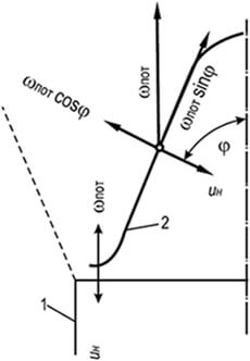
The flame front can be stopped if a counter-movement of the combustible mixture is created at a speed equal to the normal speed of flame propagation. A good example is the surface of the inner cone of a Bunsen burner. By regulating the composition of the gas-air mixture flowing from the burner in a laminar mode of movement, it is possible to achieve the appearance of a stable and sharply defined combustion cone (Fig. 8.3). The side surface of the cone (flame front), stationary relative to the fire edge of the burner channel, moves towards the flowing gas-air mixture, and the flame in this case propagates normal to the ignition surface at each of its points. On the surface of the conical flame front, the equality of velocities is maintained - the projections of the flow velocity of the gas-air mixture onto the normal wн to the generatrix of the cone and the normal flame propagation speed u n obey Michelson's law:
w n = w sweat cosφ = u n (8.26)
where φ is the angle between the flow direction and the normal to the surface of the conical flame front; w sweat - the average flow rate of the gas-air mixture passing through the burner per unit of time, m/s.
The constancy of the normal flame propagation speed is valid only for the main part of the lateral surface of the conical flame front. At the top of the cone, the speed increases due to the heating of the gas-air mixture by closely spaced sections of the conical surface of the flame front, and at the base of the cone it decreases due to the cooling effect of the end part of the burner fire channel.
For practical calculations, this difference is usually neglected and the speed of passage of the mixture through the flame front is assumed to be constant over the entire surface of the cone and equal to u n.
The average normal flame propagation speed is
u n = V cm /S (8.27)
where V cm is the volume of the gas-air mixture passing through the burner, S is the surface area of the conical flame front.
In practice, the conical flame front does not have the correct geometric shape, therefore, to accurately determine S, the flame is photographed and the flame front is divided into a number of truncated cones. The sum of the lateral surfaces is the total surface of the conical flame front. The values of normal flame propagation velocities, determined both by the Bunsen burner method and by other methods, are the same and equal to the normal velocities given in Table. 8.14.
The height of the conical flame front depends mainly on the size of the burner fire channel. Reducing the flame height can be achieved by splitting large fire channels into several small ones. For gas-air mixtures of identical composition, the height of the conical flame fronts of small channels h can be approximately determined from the height of the flame front of a single channel H:
h = Н/ √n(8.28)
where n is the number of small channels.
For burners with high thermal power (burners of industrial boilers, furnaces, etc.), combustion, as a rule, occurs in a turbulent flow - the smooth conical flame front is blurred due to vortex motion and pulsations and loses its clear conical outline. In this case, two characteristic types of combustion are observed, corresponding to small- and large-scale turbulence.
When the scale of turbulence does not exceed the thickness of the laminar combustion zone, the conical flame front retains its shape and remains smooth, although the combustion zone increases. If the scale of turbulence exceeds the thickness of the normal combustion zone, the surface of the conical flame front becomes uneven. This leads to an increase in the total surface of the combustion front and the combustion of a larger amount of combustible mixture per unit cross-section of the flow.
With large-scale turbulence, significantly exceeding the thickness of the laminar combustion zone, agitation of the surface of the flame front leads to the separation of individual particles of the hot mixture, which are crushed by subsequent pulsations. The flame front loses its integrity and turns into a system of separate combustion centers in the form of equal particles of the combustible mixture, dismembered and burned in the flow.

Rice. 8.4. Change in relative speed
coke oven gas flame spread
mixed with air depending on the number
Reynolds and mixture movement mode
With large-scale turbulence, the surface of the flame front, consisting of the surfaces of all burning particles, increases, leading to a sharp increase in the speed of flame propagation (Fig. 8.4). In this case, not only frontal combustion can occur, propagating at a normal speed vn, but also volumetric combustion, arising due to turbulent pulsations of hot combustion products into the fresh mixture. Consequently, the total speed of flame propagation during large-scale turbulence is determined by one or another combination of elements of frontal and volumetric combustion.
In the absence of pulsations, the turbulent combustion speed becomes equal to the normal flame propagation speed. On the contrary, if the pulsation velocity significantly exceeds the normal one, the turbulent combustion rate becomes little dependent on the physicochemical properties of the combustible mixture. Experiments have shown a small dependence of the combustion rate of various homogeneous gas-air mixtures with α>1 in industrial furnaces on the normal flame propagation speed.
8.8. BURNING STABILITY
Rice. 8.5. Direct compensation scheme
u n =w sweat with laminar movement
gas-air mixture
1 – burner wall;
2 – flame front
The main factors influencing combustion stability are the flow rate of the gas-air mixture and flame propagation. When burning gas-air mixtures in a laminar flow, the stable part of the conical flame front is its lower part. In this place, the flame front, due to the expansion of the gas-air mixture flowing into the atmosphere and the braking effect of the channel wall, is turned horizontally and raised above the edge of the channel by the thickness of the flame front (Fig. 8.5).
In this section of the front, the speed of the gas-air flow is completely compensated by the speed of flame propagation u n = w sweat. Throughout the rest of the conical section of the flame front, compensation is partial and is carried out only in the direction normal to the combustion front: u n = w pot cosφ. The component w pot sinφ remains unbalanced and moves the ignition point from the base of the cone to its top. The stability of the conical flame front is explained by the fact that the annular belt at the base serves as an ignition source, without which the rest of the front would be carried away by the flow of the gas-air mixture.
If the flow rate of the mixture exceeds the speed of flame propagation, the width of the ignition belt decreases until it becomes negligible. In this case, the stability of the flame front is disrupted and separation from the burner occurs. If the speed of flame propagation in the annular wall region (not on the wall) exceeds the speed of outflow of the gas-air mixture, the flame is drawn into the burner mixer (breakthrough).
When detached, the following are observed:
- the flame breaks off the burner and goes out;
- separation from the edge of the fire channel when the flame reaches a new sufficiently stable position in the flow above the burner;
- failure of the raised flame and its extinction;
- throwing the raised torch to the edge of the burner fire channel;
- creating a suspended flame when the jet is ignited at some distance from the burner.
All these phenomena are unacceptable, as they lead to the accumulation of unburned gas in the surrounding atmosphere or in the firebox.
Rice. 8.6. Dependence of the speed of separation of a single
flame in an open atmosphere of mixtures of natural
gas with air on the size of the fire channel and
primary air content.
Rice. 8.7. Dependence of lift-off speed
multi-flame flame in open atmosphere
mixtures of natural gas with air depending on the size
fire channel and primary air content.
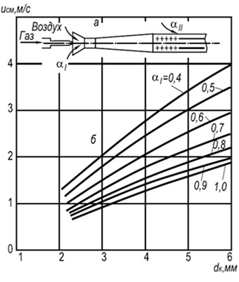
a – burner diagram; b – flame lift-off curves
In Fig. Figure 8.6 shows the experimental curves of flame separation from the edges of the fire channels of single-flame injection burners operating on a mixture of cold gas and air. At the boundary and above the indicated curves, flame separation begins, and below the curves, stable combustion begins.
In practice, multi-flare injection burners with fire channels with a diameter of 2–6 mm are widely used (Fig. 8.7). Establishment of flame separation rates w neg for such burners can be done using the following formula:
w negative = 3.5 10 -3 d k T 2 (1 + V t)/(1 + α 1 V t)(8.29)
where d k is the diameter of the fire channels, m; α 1 - coefficient of excess primary air; T is the absolute temperature of the gas-air mixture, K.
The formula shows that combustion stability increases with increasing fire channel diameters and temperature and decreases with increasing primary air excess coefficient. Combustion stability is also increased due to the mutual influence of the flame.
Flame separation from the fire channels can also occur for other reasons. If the burner and combustion product exhaust channels are incorrectly positioned, they can enter the burner injector and lead to flame separation (by reducing the speed of flame propagation in the gas-air mixture diluted with inert gases). Also, the cause of separation may be the high speed of the secondary air, blowing away the flame from the fire channels.
Table 8.15. The speed of a homogeneous mixture of natural
gas with air, at which breakthrough occurs
flame, m/s (mixture temperature 20°C)
| Diameters fire channels |
Primary air excess coefficient | |||||
|---|---|---|---|---|---|---|
| 0,6 | 0,7 | 0,8 | 0,9 | 1,0 | 1,1 | |
| 3,5 | 0,05 | 0,10 | 0,18 | 0,22 | 0,23 | 0,21 |
| 4,0 | 0,08 | 0,12 | 0,22 | 0,25 | 0,26 | 0,20 |
| 5,0 | 0,09 | 0,16 | 0,27 | 0,31 | 0,31 | 2,23 |
| 6,0 | 0,11 | 0,18 | 0,32 | 0,38 | 0,39 | 0,26 |
| 7,0 | 0,13 | 0,22 | 0,38 | 0,44 | 0,45 | 0,30 |
| 8,0 | 0,15 | 0,25 | 0,43 | 0,50 | 0,52 | 0,35 |
| 9,0 | 0,17 | 0,28 | 0,48 | 0,57 | 0,58 | 0,39 |
| 10,0 | 0,20 | 0,30 | 0,54 | 0,64 | 0,65 | 0,43 |
Flame penetration into the burner mixer, usually accompanied by a pop, is also unacceptable. A slip leads either to the extinguishing of the flame and the release of the unburned mixture into the room or firebox, or to the combustion of the mixture inside the burner. The tendency of the flame to breakthrough depends on the type of gas, the normal speed of flame propagation, the content of primary air in the gas-air mixture, the size of the fire channels, the temperatures of the mixture or the walls of the channels. Flame penetration is also influenced by the thermal conductivity coefficient of the materials from which the fire channels are made, their shape, depth and workmanship, the presence of burrs, broken edges, etc.
Given in table. 8.15, the values of the velocities of homogeneous mixtures of natural gases with air at which breakthrough occurs can also be used for other gases, taking into account the corrections:
w" pr = w pr u" n /u n (8.30)
where w‘ pr is the flame breakthrough speed for another gas, m/s; w pr - breakthrough speed for natural gas (according to Table 8.15), m/s; u‘ n - normal flame propagation speed for another gas, m/s; u n - flame propagation speed in methane, m/s.
The maximum breakthrough speed can be calculated using the approximate formula:
w pr = 0.73 10 -3 d k T 2 (8.31)
The same formula, with a sufficient approximation for practice, can be used for other gases with the introduction of a correction for changes in the normal speed of flame propagation. Based on numerous experiments, the following conclusion can be drawn: the limits of stable operation of burners are limited by the speeds of flame separation and breakthrough.
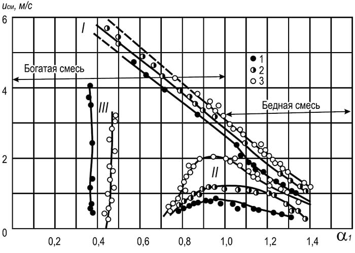
Rice. 8.8. Dependence of the speed of the gas-air mixture at which flame separation and breakthrough occurs on the coefficient of excess primary air
I – flame separation; II – flame breakthrough; III – yellow edges of the flame;
1–3 diameters of burner fire channels, mm: 1 – 25, 2 – 25, 3 – 32
In Fig. Figure 8.8 shows curves characterizing the flow rates of a mixture of natural gas and air at which flame separation and breakthrough occur. The nature of the curves indicates a sharp decrease in flame stability as the content of primary air in the mixture increases. An increase in flame stability occurs as the primary air content decreases and reaches a maximum when it decreases to zero (diffusion combustion). However, such combustion of hydrocarbon gases is in many cases unacceptable, since it leads to the appearance of yellow flames, which characterize the appearance of soot particles in it.
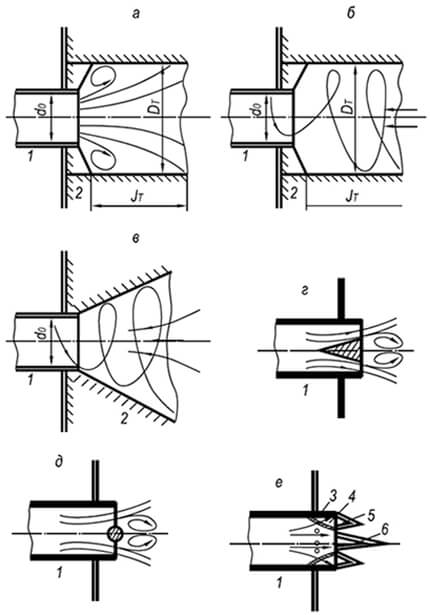
Rice. 8.9. Common combustion stabilizers
a – cylindrical tunnel with a sudden expansion of the cross-section;
b – the same, with a swirling flow;
c – conical tunnel with swirling flow;
d – stabilizer in the form of a conical body;
d – the same, in the form of a round rod;
e - the same, in the form of a stable annular flame
1 – burner fire nozzle; 2 – tunnel; 3 – side hole;
4 – ring channel; 5 – ring flame;
6 – flame of the main flow of gas-air mixture
In practice, to expand the range of combustion stability of any flammable gas-air mixtures, the flow rate is taken to be several times greater than the separation velocity. Preventing flame separation is achieved by using combustion stabilizers (Fig. 8.9).
To stabilize the flame of injection and other burners that produce axisymmetric gas-air jets, fire-resistant cylindrical tunnels with a sudden expansion of their cross-section are used. The action of such a tunnel is based on the peripheral circulation of part of the hot combustion products, which occurs due to the rarefaction created by the jet.
To stabilize the flame of burners that produce a swirling gas-air mixture, both cylindrical and conical tunnels with an opening angle of 30–60° are used. With a swirling flow, greater pressure arises at the periphery of the tunnel than in its central part. This leads to axial recirculation of part of the hot combustion products and ignition of the cold gas-air mixture flowing into the tunnel from the inside.
When installing tunnels is impossible, to stabilize the flame, poorly streamlined bodies are used, placed in the flow of the gas-air mixture at its exit from the burner fire channel. In this case, ignition of the mixture occurs at the periphery of the stabilizer, behind which partial recirculation of hot gases occurs, igniting the combustible mixture from the inside. The stabilizing effect of such devices is lower than that of tunnels.
In single- and multi-flame injection burners, combustion stabilizers are widely used in the form of a special fire nozzle. The stabilizing effect of this device is based on preventing the dilution of the main flow at the root of the torch with excess air, narrowing the limits of its stability, as well as on heating and igniting the main flow along its entire periphery with a ring flame. The stability of the annular flame during separation is achieved due to such a ratio of the sections of the fire ring and the side holes, at which the speed of the gas-air mixture in the annular cavity does not exceed the normal speed of flame propagation. To prevent flame penetration into the burner mixer, the dimensions of the side holes that form the annular flame are taken to be smaller than the critical ones.
8.9. FIRE ARRESTER DIAGRAMS
Air or oxygen entering a gas pipeline can form an explosive mixture, so it is necessary to protect the pipelines from the penetration of air or oxygen into it. In all explosive production facilities, conditions must be created that exclude the possibility of ignition impulses. Sources of ignition that lead gas-air mixtures to an explosion are:
- open flame;
- electrical discharges of operating electrical equipment;
- short circuit in electrical wires;
- sparking in electrical appliances;
- blown open fuses;
- discharges of static electricity.
Explosion safety is ensured by various fire arresters. installed in pipelines, on tanks, on purge gas pipelines, candles and other systems where there is a danger of explosion.
The extinction of a flame in a channel filled with a flammable mixture occurs only at a minimum channel diameter, depending on the chemical composition and pressure of the mixture, and is explained by heat losses from the reaction zone to the channel walls. As the diameter of the channel decreases, its surface per unit mass of the reacting mixture increases, i.e. heat loss increases. When they reach a critical value, the rate of combustion reaction decreases so much that further spread of the flame becomes impossible.
The flame extinguishing ability of a fire arrester depends mainly on the diameter of the extinguishing channels and much less on their length, and the possibility of flame penetration through the extinguishing channels depends mainly on the properties and composition of the combustible mixture and pressure. The normal speed of flame propagation is the main quantity that determines the size of the extinguishing channels and the choice of the type of fire arrester: the larger it is, the smaller the channel required to extinguish the flame. Also, the dimensions of the extinguishing channels depend on the initial pressure of the combustible mixture. To assess the flame extinguishing ability of fire arresters, the so-called. Peclet Re criterion:
Pe = w cm dc p p/(RT 0 λ 0)(8.32)
In the flame extinction limit, the Peclet criterion formula takes the form:
Re cr = w cm d cr c p p cr /(RT 0 λ 0)(8.33)
where w cm is the normal flame propagation speed; d is the diameter of the damping channel; d kp - critical diameter of the damping channel; c p is the specific heat capacity of gas at 0°C and constant pressure; p - gas pressure; p cr - critical gas pressure; R - universal gas constant; T 0 - absolute gas temperature; λ 0 - thermal conductivity of the original mixture.
Thus, to calculate the flame extinguishing ability of fire arresters, the following initial data are required:
- normal flame propagation speeds for flammable gas mixtures;
- the actual size of the maximum extinguishing channels of a given fire arrester.
If the obtained value is greater than Re cr = 65, the fire arrester will not delay the spread of the flame of a given combustible mixture, and vice versa, if Re< 65, огнепреградитель задержит распространение пламени. Запас надежности огнепреградителя, который находят из отношения Ре кр к вычисленному значению Ре, должен составлять не менее 2:
P = Re cr / Re = 65 / Re > 2.0 (8.34)
Using the fact of constancy of Pe cr at the flame extinguishing limit, it is possible to calculate the approximate critical diameter of the channels for any combustible mixture if the flame propagation speed, as well as the heat capacity and thermal conductivity of the gas system are known. The following critical diameters of the damping channel are recommended, mm:
- when burning a gas-air mixture - 2.9 for methane and 2.2 for propane and ethane;
- when burning oxygen mixtures in pipes (at an absolute pressure of 0.1 MPa under conditions of free expansion of combustion products) - 1.66 for methane and 0.39 for propane and ethane.
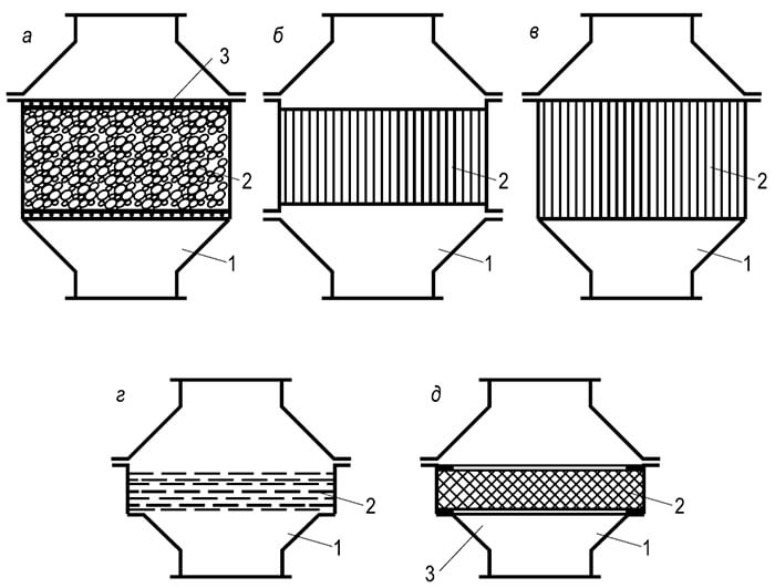
Rice. 8.10. Types of fire arresters:
a – nozzle; b – cassette; c – lamellar; g – mesh; d – metal-ceramic
Structurally, fire arresters are divided into four types (Fig. 8.10):
- with a nozzle made of granular materials;
- with straight channels;
- made of metal ceramics or metal fiber;
- mesh.
According to the installation method - into three types: on pipes for releasing gases into the atmosphere or to a flare; on communications; in front of gas burners.
In the body of the attachment fire arrester, between the gratings there is a nozzle with filler (glass or porcelain balls, gravel, corundum and other granules made of durable material). A cassette fire arrester is a housing in which a fire-retardant cassette made of corrugated and flat metal tapes, tightly wound into a roll, is mounted. The body of the plate fire arrester contains a package of plane-parallel metal plates with a strictly defined distance between them. The mesh fire arrester has a package of tightly compressed metal mesh in its body. A cermet fire arrester is a housing, inside of which a porous cermet plate in the form of a flat disk or tube is installed.
Mesh fire arresters are most often used (they began to be installed at the beginning of the 19th century in miners' lamps (Devi lamps) to prevent firedamp explosions). These fire arresters are recommended for the protection of installations in which gas fuel is burned. The fire retardant element consists of several layers of brass mesh with a cell size of 0.25 mm, sandwiched between two perforated plates. The package of nets is secured in a removable holder.
The fire arrester body is made of cast iron or aluminum alloy and consists of two identical parts connected by bolts with a removable holder located between them. In addition to the dry fire arresters discussed above, liquid safety valves are widely used to protect gas pipelines from blast waves and flames during gas-flame processing of metals, as well as pipelines and devices filled with gas from the penetration of oxygen and air into them.
Fluid seals must:
- prevent the spread of the blast wave during reverse impacts and ignition of gases;
- protect the gas pipeline from oxygen and air entering it;
- ensure minimal hydraulic resistance to the passage of gas flow. In addition, liquid from the valve should not be carried away in the form of droplets in noticeable quantities.
8.10. PRINCIPLES OF COMBUSTION
Gas combustion processes are based on principles conventionally called kinetic and diffusion. Under the kinetic principle, before combustion begins, a homogeneous mixture with some excess air is created. The combustion of such a mixture occurs in a short transparent flame without the formation of soot particles in the flame. To burn gas according to the kinetic principle, special mixers or injection burners are used to prepare a homogeneous gas-air mixture with a primary air excess ratio α 1 = 1.02:1.05.
With a lower content of primary air, according to the kinetic principle, only the initial stage of combustion occurs, before the use of oxygen mixed with gas. The remaining gases and products of incomplete combustion are burned due to external diffusion of oxygen (secondary air), i.e. according to the diffusion principle. At α 1< 1 у факела есть два видимых фронта горения: внутренний, возникающий за счет первичного воздуха, и наружный, образующийся за счет диффузии кислорода из окружающей среды. Общая высота пламени при таком горении возрастает, а температура - несколько снижается. Устойчивость пламени и его прозрачность зависят от содержания первичного воздуха в смеси: чем оно выше, тем ниже устойчивость пламени, больше его прозрачность, и наоборот.
Principle of gas combustion with α 1< 1,0 является п р о м е ж у т о ч н ы м (между кинетическим и диффузионным). С учетом этого принципа конструируются все газовые аппараты с инжекционными горелками. В таких горелках содержание первичного воздуха в смеси принимается в зависимости от вида газа таким, чтобы:
- there were no soot particles in the flame;
- stability of combustion was ensured with changes in thermal power within any limits required in practice.
With the diffusion principle (α 1 = 0), the combustion and mixing processes develop in parallel. Since mixing processes proceed much slower than combustion processes, the speed and completeness of combustion are determined by the speed and completeness of mixing of gas and air. Mixing of gas with air can occur through diffusion (either slow molecular or turbulent, which also includes molecular as the final stage). Accordingly, the burning rate and the structure of the diffusion flame differ.
Features of this combustion:
- flame stability when the thermal power changes from zero to the maximum possible under the lift-off conditions;
- constant temperature over the entire flame height;
- the ability to distribute it over large arbitrary surfaces;
- compactness of the burners and ease of their manufacture;
- significant flame height and the inevitability of pyrolytic processes leading to the formation of a bright sooty flame.
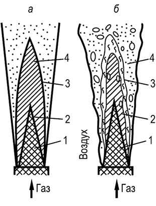
Rice. 8.11. Free flame structure:
a – laminar flame; b – turbulent flame
Diffusion combustion can be converted into kinetic or intermediate combustion if the mixing advances the combustion processes. In practice, this can be achieved by forced air supply, leading to the formation of a quasi-homogeneous gas-air mixture with α 1 > 1.0, burning in a transparent flame.
To illustrate the principles of combustion in Fig. 8.11. diagrams of free torches are shown: laminar and turbulent. A laminar plume occurs due to the mutual molecular diffusion of gas and air. Inside the conical core 1 there is pure gas flowing out of the tube in a laminar flow regime. In zone 2 there is a mixture of gas and combustion products, in zone 3 there is a mixture of combustion products and air. Boundary 4 is a smooth conical flame front, to which air molecules diffuse from the outside, and gas molecules from the inside. Combustion products partially diffuse towards the gas, intensely heating it in the pre-flame zone. This leads to pyrolysis of hydrocarbons and the formation of soot particles, which give the flame a bright luminosity.
Combustion can be intensified by turbulization of mixing flows. A turbulent flame does not have a clear conical combustion front; it is “blurred” and fragmented by pulsations into individual particles.
The flame structure consists of a pure gas core 1, a relatively slow combustion zone 2, a diffuse zone of the most intense combustion 3 with a high content of combustion products, and a combustion zone 4 with a predominance of air. There are no clearly defined boundaries between the zones; they continuously shift depending on the degree of turbulization of the flow. Features of a turbulent plume are:
- the combustion process occurs throughout almost the entire volume;
- increasing combustion intensity;
- greater flame transparency;
- its lower resistance to separation.
Turbulent combustion of gas is widely used in the combustion chambers of various boilers and furnaces. To intensify the combustion process, both natural (by increasing speeds) and artificial turbulization of flows are used, for example, by swirling the air flow and feeding thin gas jets into it at different angles.
8.11. CONDITIONS FOR FORMATION OF PRODUCTS OF INCOMPLETE COMBUSTION AND REDUCING THE CONCENTRATION OF HARMFUL SUBSTANCES IN THEM
When combustible gases are burned, combustion products may contain components of both complete (carbon dioxide and water vapor) and incomplete combustion (carbon monoxide, hydrogen, unsaturated, saturated, aromatic hydrocarbons and soot particles). In addition, nitrogen oxides are always found in combustion products. The presence of incomplete combustion products in significant concentrations is unacceptable, as it leads to atmospheric pollution with toxic substances and a decrease in the efficiency of installations operating on gas fuel.
The main reasons for their high content:
- combustion of gases with insufficient air;
- poor mixing of flammable gases and air before and during combustion;
- excessive cooling of the flame before combustion reactions are completed.
For methane, combustion reactions (depending on the oxygen concentration in the reacting mixture) can be described by the following equations:
CH 4 + 2O 2 = CO 2 + 2H 2 O + 800.9 MJ/mol
at a stoichiometric ratio or with an excess of oxidizing agent;
CH 4 + O 2 = CO + H 2 + H 2 O + Q and CH 4 + 0.5 O 2 = CO + 2H 2 O + Q
with a lack of oxidizing agent.

Rice. 8.12. Combustion intermediates

Rice. 8.13. Primary air content,
which prevents the formation
yellow tongues in the flame
Gas: 1 – coke oven;
2 – natural gas fields;
3 – oil fields;
4 – propane; 5 – butane
In Fig. Figure 8.12 shows the approximate average composition of some intermediate compounds - hydrogen, carbon monoxide, ethylene, acetylene and a relatively small number of saturated and simple aromatic compounds - and carbon dioxide that arise in the flame during diffusion combustion of natural gas (97%). The gas was burned in a laminar torch; the gas flowed out of a tube with a diameter of 12 mm. The total flame height is 130–140 mm.
The maximum concentration of hydrogen and acetylene is achieved at approximately the same flame height; they disappear almost simultaneously at the top of the luminous flame zone. Of all the intermediate compounds formed in the flame (excluding soot particles), carbon monoxide is the last to disappear. This gives grounds to judge by its index the completeness of gas combustion. Combustion products always contain nitrogen oxides, the maximum concentration of which occurs in zones of intense combustion of carbon monoxide and hydrogen.
The combustion of hydrocarbon gases with a lack of oxidizer leads to the formation of soot particles, which give the flame a yellow color. The process of soot burning out occurs in stages and is relatively slow. Sometimes the burnout of the formed soot particles is delayed and can stop completely upon entering the low-temperature region of the torch or when the heat-exchange surfaces are washed with flame. Thus, the presence of a luminous flame always indicates the occurrence of pyrolytic processes and the possibility of chemical incomplete combustion, especially in small-sized shielded boiler furnaces.
Preventing the formation of soot particles is achieved by pre-mixing hydrocarbon gases with a sufficient amount of oxidizer. The content of primary air in the mixture, at which a transparent flame occurs, depends not only on the type of hydrocarbons, but also on the conditions of mixing with secondary air (the diameter of the burner fire channels) (Fig. 8.13). At the border and above the curves the flame is transparent, and below the curves it has yellow tongues. The curves show that the content of primary air in the mixture increases with the number of carbon atoms in the molecule and the diameter of the burner fire channels. The coefficient of excess primary air α 1 in the mixture, at which the yellow flames disappear, depending on the specified factors, can be determined for small fire channels of burners:
α 1 = 0.12 (m + n/4) 0.5 (d k /d 0) 0.25 (8.35)
where m and n are the number of carbon and hydrogen atoms in a molecule or their average number for a complex gas; d k - diameter of burner fire channels, mm; d 0 - reference diameter of the burner channel (1 mm).
Ensuring complete combustion in practical conditions is a rather complex task, depending not only on the principle of gas combustion, but also on the conditions of flame development in the combustion volume. The highest requirements for complete combustion are imposed on household appliances and other installations that discharge combustion products into the atmosphere. Combustion of gas in such installations is the most difficult, as it is associated with flame washing cold heat exchange surfaces. To burn gas in household stoves, multi-flame injection burners are used, forming a homogeneous mixture with a primary air excess coefficient α 1< 1. Недостающий для сгорания газа воздух поступает за счет диффузии из окружающей атмосферы.
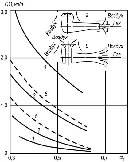
Rice. 8.14. Carbon monoxide concentration
in combustion products in a gas stove
a – burner with peripheral supply of secondary air;
b – with central and peripheral supply of secondary air
1 – natural gas, burner with peripheral supply
secondary air, distance to the bottom of the dish 25 mm;
2–4 – natural gas, burner with peripheral and
central secondary air supply, distance
to the bottom of the dish, mm: 2 – 25, 3 – 18, 4 – 10;
5 – liquefied gas, burner with central and peripheral
secondary air supply, distance to the bottom of the dish 25 mm;
6 – liquefied gas, burner with peripheral supply
In Fig. Figure 8.14 shows diagrams of 2-burner burners for household gas stoves and the average concentration of carbon monoxide CO in the combustion products of natural methane (95 vol. %) and propane (93 vol. %) when the burners operate at rated thermal power. The difference between the burners is that to one of them secondary air is supplied only from the periphery, and to the other - both from the periphery and from the central channel.
The completeness of gas combustion depends on the coefficient of excess primary air in the mixture, the distance from the burner fire channels to the bottom of the cookware, the type of combustible gas, and the method of supplying secondary air. In this case, an increase in the content of primary air in the mixture, as well as an increase in the distance from the burner to the bottom of the cookware, lead to a decrease in the concentration of carbon monoxide in the combustion products. The minimum concentration of carbon monoxide corresponds to the coefficient of excess primary air α 1 = 0.6 and above and the distance from the burner to the bottom of the cookware is 25 mm, and the maximum - α 1 = 0.3 and below and the distance from the burner to the bottom of the cookware is 10 mm. In addition, an increase in the thermal power of burners by 15–20% due to an increase in gas pressure leads to an increase in the concentration of carbon monoxide in combustion products by 1.2–1.3 times, and due to the heat of combustion of gas - by 1.5–2 times.
Particular attention should be paid to the appearance of aromatic compounds during the combustion process - benzene, polycyclic benzopyrene, benzanthracene, etc., since some of them are carcinogenic. The process of their formation is very complex and occurs in stages. At the first stage, acetylene and its derivatives appear. In the flame zone, these substances undergo chain elongation processes with the rearrangement of triple carbon bonds into double ones. As a result of cyclization and dehydration, various aromatic compounds appear, including polycyclic ones.
Table 8.16. Average concentration of carbon monoxide and benzo(a)pyrene in combustion products, depending on the type of gas, type of burner and excess primary air ratio (thermal load of the burner - 1600 kcal/h, distance from the burner to the bottom of the cookware - 24–26 mm)
| Burner type | Average concentration | |
|---|---|---|
| carbon monoxide, mg/l (in terms of α = 1.0) |
benz(a)pyrene, µg/100 m 3 |
|
| Natural gas | ||
at α i = 0.60 ÷ 0.70 |
0,10 | Not found |
at α i = 0.30 ÷ 0.35 |
1,20 | Footprints |
at α i = 0.60 ÷ 0.70 |
0,50 | Not found |
at α i = 0.30 ÷ 0.35 |
0,12 | Not found |
| Liquefied petroleum gas | ||
| Burner with peripheral secondary air supply: | ||
at α i = 0.60 ÷ 0.70 |
0,30 | 0,03 |
at α i = 0.30 ÷ 0.35 |
1,20 | 1,10 |
| Burner with central and peripheral secondary air supply: | ||
at α i = 0.60 ÷ 0.70 |
0,07 | 0,02 |
at α i = 0.30 ÷ 0.35 |
1,00 | 0,045 |
Table data 8.16 show that when burning natural gases with a primary air excess coefficient α 1 = 0.6 and higher on both types of burners, the concentration of carbon monoxide in combustion products meets the requirements of GOST 5542–87.
Table 8.17. The distance between the edges of the fire channels of single-row injection burners depending on their size and the coefficient of excess primary air
| Diameters of fire channels, mm | Distances between the edges of the channels, mm at different values of the coefficient of excess primary air α 1 | ||||
|---|---|---|---|---|---|
| 0,2 | 0,3 | 0,4 | 0,5 | 0,6 | |
| 2,0 | 11 | 8 | 6 | 5 | 4 |
| 3,0 | 15 | 12 | 9 | 7 | 5 |
| 4,0 | 16 | 14 | 11 | 9 | 7 |
| 5,0 | 18 | 15 | 14 | 12 | 10 |
| 6,0 | 20 | 18 | 16 | 14 | 12 |
Studies have shown that the distances between the edges of the fire channels, ensuring the rapid spread of the flame and preventing their merging, depend on their size and the content of primary air in the mixture, decreasing with its increase. The optimal distances between the edges of the channels, ensuring sufficient completeness of gas combustion and rapid flame spread, are given in Table. 8.17. When the fire channels are arranged in two rows in a checkerboard pattern, the distances between the edges can be taken according to the same table. The distances between the rows should be 2–3 times greater than the distances between the channels.
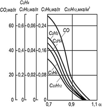
Rice. 8.15. Concentration of carbon monoxide, acetylene,
ethane, ethylene and benzo(a)pyrene in combustion products
medium pressure gas in the injection burner
Generalization of numerous experimental data made it possible to obtain average concentration curves in combustion products of various components that qualitatively and quantitatively characterize the combustion process (Fig. 8.15). Complete combustion of a homogeneous gas-air mixture is achieved only when the excess primary air coefficient is α = 1.05 and higher. When the air content in the mixture decreases, especially at α< 1,0, возрастает концентрация оксида углерода СО, ацетилена С 2 Н 2 , этилена С 2 Н 4 , пропилена С 3 Н 6 и пропана С 3 Н 8 , а также бенз(а)-пирена С 20 Н 9 . Также возрастает концентрация и других компонентов - водорода, бензола и др.
In addition to the considered products of incomplete combustion, gas combustion always produces a certain amount of nitrogen oxides, the formation of which occurs in high temperature zones both after the completion of the main combustion reactions and during the combustion process. The maximum concentration of NO x occurs at the final stages, corresponding to gas burnout and intense combustion of intermediate products in the form of hydrogen and carbon monoxide.
The primary compound during combustion of gas-air mixtures is nitrogen oxide. The beginning of the chain reaction is associated with atomic oxygen arising in high temperature zones due to the dissociation of molecular oxygen:
О 2 –› 2О - 490 kJ/mol (8.36)
O + N 2 –› NO + N - 300 kJ/mol (8.37)
N + O 2 –› 2NO + 145 kJ/mol (8.38)
Balance reaction
N 2 + O 2 –› 2NO - 177 kJ/mol (8.39)
The formation of atomic oxygen also occurs during partial dissociation of combustion products: with a decrease in temperature and the presence of oxygen, part of the resulting nitrogen oxide (1-3 vol. %) is oxidized to nitrogen dioxide NO 2. The reaction occurs most intensely after the release of nitrogen oxide into the atmosphere. Main influencing factors:
- temperature in reaction zones;
- excess air ratio and contact time of reacting components.
The flame temperature depends on the chemical composition of the gas, the air content in the gas-air mixture, the degree of its homogeneity and heat removal from the reaction zone. The maximum possible concentration of nitrogen oxide at a given temperature, vol. %, can be calculated using the formula
NO p = 4.6е -2150/(RT) /√О 2 N 2 (8.40)
where NO p is the equilibrium concentration of nitrogen oxide, vol. %; R - universal gas constant; T - absolute temperature, K; O 2 and N 2 - concentration, vol. %, respectively, oxygen and nitrogen.
A high concentration of nitrogen oxide, comparable to the equilibrium one, occurs when gas is burned in the furnaces of powerful steam generators and in high-temperature open-hearth, coke and similar ovens. In boilers of low and medium power, in small heating and thermal furnaces with significant heat removal and short residence time of components in high-temperature zones, the yield of nitrogen oxide is an order of magnitude lower. In addition, the shorter the residence time of the reacting components in the high temperature zone, the less nitrogen oxide in the combustion products.
Combustion of gas in radiant burners and in a fluidized bed is also effective: in these cases, microflare combustion of a homogeneous gas-air mixture occurs with an excess air coefficient α = 1.05 with very intensive heat removal from the reaction zone. The concentration of nitrogen oxides when burning gas in radiant burners is about 40, and in a fluidized bed - 80–100 mg/m3. Reducing the size of the fire channels of radiant burners and refractory grains in the fluidized bed helps reduce the yield of nitrogen oxides.
The accumulated data made it possible to make a number of changes to the design of boiler and heating equipment, ensuring not only high efficiency and low concentration of incomplete combustion products, but also reduced discharge of nitrogen oxides into the atmosphere. These changes include:
- reducing the length of high-temperature tunnels and moving combustion from them to the furnaces;
- the use of combustion stabilizers in the form of poorly streamlined bodies or annular flames instead of ceramic tunnels;
- organization of a flat flame with an increased heat transfer surface;
- flame dispersion by increasing the number of burners or using block burners;
- stepped air supply to the reaction zone;
- uniform distribution of heat flows in the firebox, screening of fireboxes and their division into compartments by screens;
- application of the diffusion principle of gas combustion (diffusion combustion is permissible only in cases where free development of the flame can be ensured without washing the heat exchange surfaces).
The most effective reduction in the yield of nitrogen oxides is achieved by using several methods simultaneously.
Natural gas is the most common fuel today. Natural gas is called natural gas because it is extracted from the very depths of the Earth.
The process of gas combustion is a chemical reaction in which natural gas interacts with oxygen contained in the air.
In gaseous fuel there is a combustible part and a non-combustible part.
The main flammable component of natural gas is methane - CH4. Its content in natural gas reaches 98%. Methane is odorless, tasteless and non-toxic. Its flammability limit is from 5 to 15%. It is these qualities that have made it possible to use natural gas as one of the main types of fuel. A methane concentration of more than 10% is life-threatening; suffocation can occur due to lack of oxygen.
To detect gas leaks, the gas is odorized, in other words, a strong-smelling substance (ethyl mercaptan) is added. In this case, the gas can be detected already at a concentration of 1%.
In addition to methane, natural gas may contain flammable gases - propane, butane and ethane.
To ensure high-quality combustion of gas, it is necessary to supply sufficient air to the combustion zone and ensure good mixing of gas with air. The optimal ratio is 1: 10. That is, for one part of gas there are ten parts of air. In addition, it is necessary to create the desired temperature regime. In order for a gas to ignite, it must be heated to its ignition temperature and in the future the temperature should not fall below the ignition temperature.
It is necessary to organize the removal of combustion products into the atmosphere.
Complete combustion is achieved if there are no flammable substances in the combustion products released into the atmosphere. In this case, carbon and hydrogen combine together and form carbon dioxide and water vapor.
Visually, with complete combustion, the flame is light blue or bluish-violet.
Complete combustion of gas.
methane + oxygen = carbon dioxide + water
CH 4 + 2O 2 = CO 2 + 2H 2 O
In addition to these gases, nitrogen and remaining oxygen are released into the atmosphere with flammable gases. N2+O2
If gas combustion does not occur completely, then flammable substances are released into the atmosphere - carbon monoxide, hydrogen, soot.
Incomplete combustion of gas occurs due to insufficient air. At the same time, tongues of soot visually appear in the flame.
The danger of incomplete combustion of gas is that carbon monoxide can cause poisoning of boiler room personnel. A CO content in the air of 0.01-0.02% can cause mild poisoning. Higher concentrations can cause severe poisoning and death.
The resulting soot settles on the walls of the boiler, thereby impairing the transfer of heat to the coolant and reducing the efficiency of the boiler room. Soot conducts heat 200 times worse than methane.
Theoretically, 9m3 of air is needed to burn 1m3 of gas. In real conditions, more air is required.
That is, an excess amount of air is needed. This value, designated alpha, shows how many times more air is consumed than is theoretically necessary.
The alpha coefficient depends on the type of specific burner and is usually specified in the burner passport or in accordance with the recommendations for organizing the commissioning work being carried out.
As the amount of excess air increases above the recommended level, heat loss increases. With a significant increase in the amount of air, a flame may break off, creating an emergency situation. If the amount of air is less than recommended, combustion will be incomplete, thereby creating a risk of poisoning for boiler room personnel.
For more accurate control of the quality of fuel combustion, there are devices - gas analyzers, which measure the content of certain substances in the composition of exhaust gases.
Gas analyzers can be supplied complete with boilers. If they are not available, the corresponding measurements are carried out by the commissioning organization using portable gas analyzers. A regime map is drawn up in which the necessary control parameters are prescribed. By adhering to them, you can ensure normal complete combustion of the fuel.
The main parameters for regulating fuel combustion are:
- the ratio of gas and air supplied to the burners.
- excess air coefficient.
- vacuum in the furnace.
- Boiler efficiency factor.
In this case, the efficiency of the boiler means the ratio of useful heat to the amount of total heat expended.
Air composition
| Gas name | Chemical element | Contents in the air |
| Nitrogen | N2 | 78 % |
| Oxygen | O2 | 21 % |
| Argon | Ar | 1 % |
| Carbon dioxide | CO2 | 0.03 % |
| Helium | He | less than 0.001% |
| Hydrogen | H2 | less than 0.001% |
| Neon | Ne | less than 0.001% |
| Methane | CH4 | less than 0.001% |
| Krypton | Kr | less than 0.001% |
| Xenon | Xe | less than 0.001% |
Depending on the method of formation of the gas-air mixture, gas combustion methods are divided (picture below):
- to diffusion;
- mixed;
- kinetic.
Gas combustion methods
a - diffusion; b - mixed; c - kinetic; 1 - internal cone; 2 - primary combustion zone; 3 - main combustion zone; 4 - combustion products; 5 - primary air; 6 - secondary air
With the diffusion combustion method, gas is supplied to the combustion front under pressure, and the air necessary for combustion is supplied from the surrounding space due to molecular or turbulent diffusion. Mixture formation here occurs simultaneously with the combustion process, so the rate of the combustion process is mainly determined by the rate of mixture formation.
The combustion process begins after contact between gas and air and the formation of a gas-air mixture of the required composition. Air diffuses to the gas stream, and gas diffuses from the gas stream into the air. Thus, a gas-air mixture is created near the gas stream, as a result of the combustion of which a primary gas combustion zone 2 is formed. The combustion of the main part of the gas occurs in zone 3, and combustion products move in zone 4.
The released combustion products complicate the mutual diffusion of gas and air, as a result of which combustion proceeds slowly, with the formation of soot particles. This explains that diffusion combustion is characterized by a significant length and luminosity of the flame.
The advantage of the diffusion method of gas combustion is the ability to regulate the combustion process over a wide range. The mixture formation process is easily controlled by using various control elements. The area and length of the torch can be adjusted by splitting the gas stream into separate torches, changing the diameter of the burner nozzle, adjusting the gas pressure, etc.
The advantages of the diffusion combustion method include: high flame stability when thermal loads change, no flame breakthrough, temperature uniformity along the length of the flame.
The disadvantages of this method are: the likelihood of thermal decomposition of hydrocarbons, low combustion intensity, and the likelihood of incomplete combustion of gas.
With the mixed combustion method, the burner provides preliminary mixing of gas with only part of the air necessary for complete combustion of the gas; the rest of the air comes from the environment directly to the torch. In this case, first only part of the gas mixed with primary air burns out, and the remaining part of the gas, diluted with combustion products, burns out after the addition of oxygen from the secondary air. As a result, the torch is shorter and less luminous than with diffusion combustion.
With the kinetic combustion method, a gas-air mixture is supplied to the combustion site, completely prepared inside the burner. The gas-air mixture burns in a short flame. The advantages of this combustion method are the low probability of chemical underburning, short flame length, and high heat output of the burners. The disadvantage is the need to stabilize the gas flame.
COMBUSTION OF NATURAL GAS. Combustion is a reaction that converts the chemical energy of a fuel into heat. Combustion can be complete or incomplete. Complete combustion occurs when there is sufficient oxygen. Its lack causes incomplete combustion, during which less heat is released than during complete combustion, and carbon monoxide (CO), which has a poisonous effect on operating personnel, soot is formed, settling on the heating surface of the boiler and increasing heat loss, which leads to excessive fuel consumption and a decrease in boiler efficiency, air pollution.
To burn 1 m3 of methane, you need 10 m3 of air, which contains 2 m3 of oxygen. To ensure complete combustion of natural gas, air is supplied to the furnace with a slight excess.
The ratio of the actually consumed air volume Vd to the theoretically required Vt is called the excess air coefficient = Vd/Vt. This indicator depends on the design of the gas burner and furnace: the more advanced they are, the smaller . It is necessary to ensure that the excess air coefficient is not less than 1, as this leads to incomplete combustion of the gas. An increase in the excess air ratio reduces the efficiency of the boiler unit. The completeness of fuel combustion can be determined using a gas analyzer and visually - by the color and nature of the flame: transparent bluish - complete combustion; red or yellow - combustion is incomplete.
Combustion is regulated by increasing the air supply to the boiler furnace or decreasing the gas supply. This process uses primary (mixed with gas in the burner - before combustion) and secondary (combined with gas or gas-air mixture in the boiler furnace during combustion) air. In boilers equipped with diffusion burners (without forced air supply), secondary air, under the influence of vacuum, enters the furnace through the purge doors.
In boilers equipped with injection burners: primary air enters the burner due to injection and is regulated by an adjusting washer, and secondary air enters through the purge doors. In boilers with mixing burners, primary and secondary air is supplied to the burner by a fan and controlled by air valves. Violation of the relationship between the speed of the gas-air mixture at the outlet of the burner and the speed of flame propagation leads to separation or jumping of the flame on the burners.
If the speed of the gas-air mixture at the burner exit is greater than the speed of flame propagation, there is separation, and if it is less, there is breakthrough. If the flame breaks out and breaks through, the maintenance personnel must extinguish the boiler, ventilate the firebox and flues and re-ignite the boiler. Gaseous fuel is increasingly used every year in various sectors of the national economy.
In agricultural production, gaseous fuel is widely used for technological (for heating greenhouses, greenhouses, dryers, livestock and poultry complexes) and domestic purposes. Recently, it has become increasingly used for internal combustion engines. Compared to other types, gaseous fuel has the following advantages: it burns in a theoretical amount of air, which ensures high thermal efficiency and combustion temperature; upon combustion does not form undesirable products of dry distillation and sulfur compounds, soot and smoke; it is relatively easily supplied through gas pipelines to remote consumption facilities and can be stored centrally; ignites easily at any ambient temperature; requires relatively low production costs, which means it is a cheaper type of fuel compared to other types; can be used in compressed or liquefied form for internal combustion engines; has high anti-knock properties; does not form condensate during combustion, which ensures a significant reduction in wear of engine parts, etc. At the same time, gaseous fuel also has certain negative properties, which include: a poisonous effect, the formation of explosive mixtures when mixed with air, easy flow through leaks in connections, etc. Therefore, when working with gaseous fuel, careful compliance with the relevant safety regulations is required.
The use of gaseous fuels is determined by their composition and properties of the hydrocarbon part.
The most widely used are natural or associated gas from oil or gas fields, as well as industrial gases from oil refineries and other plants. The main components of these gases are hydrocarbons with the number of carbon atoms in a molecule from one to four (methane, ethane, propane, butane and their derivatives). Natural gases from gas fields consist almost entirely of methane (82–98%), with little use of gaseous fuel for internal combustion engines. The continuously increasing fleet of vehicles requires more and more fuel. It is possible to solve the most important national economic problems of stable supply of automobile engines with efficient energy carriers and reducing the consumption of liquid fuels of petroleum origin through the use of gaseous fuels - liquefied petroleum and natural gases.
For cars, only high-calorie or medium-calorie gases are used. When running on low-calorie gas, the engine does not develop the required power, and the vehicle’s range is also reduced, which is economically unprofitable.
Pa). The following types of compressed gases are produced: natural, mechanized coke and enriched coke. The main flammable component of these gases is methane.
As with liquid fuel, the presence of hydrogen sulfide in gaseous fuel is undesirable due to its corrosive effect on gas equipment and engine parts. The octane number of gases allows you to boost car engines in terms of compression ratio (up to 10 12). The main flammable component of these gases is methane.
As with liquid fuel, the presence of hydrogen sulfide in gaseous fuel is undesirable due to its corrosive effect on gas equipment and engine parts. The octane number of gases allows you to boost car engines in terms of compression ratio (up to 10 12). The presence of cyanogen CN in gas for cars is extremely undesirable. When combined with water, it forms hydrocyanic acid, under the influence of which tiny cracks are formed in the walls of the cylinders.
The presence of resinous substances and mechanical impurities in gas leads to the formation of deposits and contaminants on gas equipment and engine parts. 2.4 LIQUID FUEL AND ITS CHARACTERISTICS The main type of liquid fuel used in boiler houses is fuel oil - the final product of oil refining.
Main characteristics of fuel oil: viscosity, pour point For reliable and durable operation of mechanisms and systems, fuel and lubricants must comply with GOST requirements. At the same time, the main criterion characterizing the quality of fuel and lubricants is physical and chemical properties. Let's look at the main ones. Density is the mass of a substance contained in a unit volume. A distinction is made between absolute and relative density. Absolute density is defined as: where p is density, kg/m3; m is the mass of the substance, kg; V - volume, m3. Density is important when determining the weight of fuel in tanks.
The density of any liquid, including fuel, changes with temperature. For most petroleum products, density decreases with increasing temperature and increases with decreasing temperature. In practice, we often deal with a dimensionless quantity - relative density. The relative density of an oil product is the ratio of its mass at the temperature of determination to the mass of water at a temperature of 4 °C, taken in the same volume, since the mass of 1 liter of water at 4 °C is exactly equal to 1 kg. Relative density (specific gravity) is indicated by 20 4 r. For example, if 1 liter of gasoline at 20 °C weighs 730 g, and 1 liter of water at 4 °C weighs 1000 g, then the relative density of gasoline will be equal to: The relative density of the petroleum product 20 4 p is usually expressed as a value related to normal temperature (+20 °C), at which density values are regulated by the state standard.
In passports characterizing the quality of petroleum products, the density is also indicated at a temperature of +20 °C. If the density t 4 p at a different temperature is known, then from its value it is possible to calculate the density at 20 ° C (i.e., bring the actual density to standard conditions) using the formula: where Y is the average temperature correction of density, a value that is taken depending on from the value of the measured density t 4 p according to the table Temperature corrections to the density of petroleum products Considering the density as a weight, by volume t V and density t 4 p (measured at the same temperature t) the weight of the fuel at the measured temperature is found: With increasing temperature the volume of petroleum products increases and is determined by the formula: where 2 V is the volume of petroleum products with an increase in temperature by 1 °C; 1 V - initial volume of oil product; delta t - temperature difference; B - coefficient of volumetric expansion of petroleum product Coefficients of volumetric expansion of petroleum products depending on density at +20 °C per 1 °C The most common methods for measuring density are hydrometric, pycnometric and hydrostatic weighing.
Recently, automatic methods have been successfully developed: vibration, ultrasonic, radioisotope, hydrostatic.
Viscosity is the property of liquid particles to resist mutual movement under the influence of an external force. A distinction is made between dynamic and kinematic viscosity.
In practical conditions, one is more interested in kinematic viscosity, which is equal to the ratio of dynamic viscosity to density.
The viscosity of a liquid is determined in capillary viscometers and measured in Stokes (C), the dimension of which is mm2/s. The kinematic viscosity of petroleum products is determined according to GOST 33-82 in capillary viscometers VPZh-1, VPZh-2 and Pinkevich (Fig. 5). The viscosity of transparent liquids at positive temperatures is determined using VPZh-1 viscometers. Viscometers VPZh-2 and Pinkevich are used for various temperatures and liquids.
The kinematic viscosity of fuel intended for use in high-speed diesel engines is standardized at 20 °C, low-speed - at 50 °C, motor oils - at 100 °C. The determination of kinematic viscosity in a capillary viscometer is based on the fact that the viscosity of a liquid is directly proportional to the time it flows through the capillary, which ensures laminar flow. The Pinkevich viscometer consists of communicating tubes of varying diameters.
For each viscometer, its constant C is indicated, which is the ratio of the viscosity of the calibration liquid to 20 v at 20 ° C to the time of flow to 20 t of this liquid under the influence of its own mass, also at 20 ° C, from volume 2 from mark a to mark b through capillary 3 in extension 4: The viscosity of the petroleum product at temperature t °C is determined by the formula: The fractional composition is determined according to GOST 2177-82 using a special device. To do this, 100 ml of the test fuel is poured into flask 1 and heated to boiling. Fuel vapor enters refrigerator 3, where it condenses and then enters measuring cylinder 4 in the form of a liquid phase. During the distillation process, the temperature at which 10, 20, 30%, etc. boils off is recorded. of the fuel under study.
The distillation is completed when, after reaching the highest temperature, a slight drop in temperature is observed. Based on the distillation results, a fractional distillation curve of the test fuel is constructed. The first is the starting fraction, caused by the boiling away of 10% of the fuel, characterizing its starting qualities. The lower the boiling point of this fraction, the better for starting the engine.
For winter grades of gasoline, it is necessary that 10% of the fuel boils away at a temperature no higher than 55 °C, and for summer grades - no higher than 70 °C. The other part of gasoline, boiling away from 10 to 90%, is called the working fraction. The temperature of its evaporation should not be higher than 160 ... 180 ° C. The heavy hydrocarbons of gasoline in the range from 90% boiling point to the end boiling point represent the end or tail fractions, which are extremely undesirable in fuel.
The presence of these fractions leads to negative phenomena during engine operation: incomplete combustion of fuel, increased wear of parts due to washing off the lubricant from the cylinder liners and diluting the engine oil in the engine, increasing the performance properties of diesel fuel Diesel fuel is used in compression ignition engines, called diesel engines. Air and fuel are supplied to the combustion chamber separately.
During suction, fresh air enters the cylinder; during the second compression stroke, the air is compressed to 3 ... 4 MPa (30 ... 40 kgf/cm2). As a result of compression, the air temperature reaches 500 ... 700 ° C. At the end of compression, fuel is injected into the engine cylinder, forming a working mixture that is heated to the auto-ignition temperature and ignites. The injected fuel is atomized by a nozzle, which is placed in the combustion chamber or in the prechamber. The average diameter of fuel droplets is approximately 10 ... 15 microns. Compared to carburetor engines, diesel engines are highly economical, as they operate with higher compression ratios (12 ... 20 instead of 4 ... 10) and an excess air ratio = 5.1 4.1. As a result, their specific fuel consumption is 25 ... 30% lower than that of carburetor engines. Diesel engines are more reliable in operation and more durable, they have better throttle response, i.e. pick up speed more easily and overcome overloads.
At the same time, diesel engines are more complex to manufacture, larger in size and have less power per unit weight. But, based on more economical and reliable operation, diesel engines successfully compete with carburetor engines.
To ensure durable and economical operation of a diesel engine, diesel fuel must meet the following requirements: have good mixture formation and flammability; have appropriate viscosity; have good pumpability at different ambient temperatures; do not contain sulfur compounds, water-soluble acids and alkalis, mechanical impurities and water. The property of diesel fuel, which characterizes the soft or hard operation of a diesel engine, is assessed by its self-ignition.
This characteristic is determined by comparing diesel engines running on test and reference fuels. The cetane number of the fuel is an evaluation indicator. The fuel entering the diesel cylinders does not ignite instantly, but after a certain period of time, which is called the auto-ignition delay period.
The smaller it is, the shorter the period of time the fuel burns in the diesel cylinders. Gas pressure increases smoothly, and the engine runs smoothly (without sudden knocks). With a long delay period for self-ignition, the fuel burns in a short period of time, the gas pressure increases almost instantly, so the diesel engine operates harshly (with a knock). The higher the cetane number, the shorter the delay period for the auto-ignition of diesel fuel, the softer the auto-ignition of diesel fuel is usually assessed by comparing it with the auto-ignition of reference fuels.
The standard fuels used are the normal paraffin hydrocarbon cetane (C16H34), which has a short period of auto-ignition delay (the auto-ignition of cetane is conventionally taken as 100) and the aromatic hydrocarbon methylnaphthalene C10H7CH3, which has a long delay of self-ignition (its self-ignition is conventionally taken as 0) when the engine is running.
The cetane number of the fuel is numerically equal to the percentage of cetane in its mixture with methylnaphthalene, which in terms of the nature of combustion (self-ignition) is equivalent to the test fuel. Using standard fuels, it is possible to obtain mixtures with any cetane number from 0 to 100. The cetane number can be determined in three ways: by coincidence of flashes, by self-ignition delay and by the critical compression ratio. The cetane number of diesel fuels is usually determined using the “flash coincidence” method using IT9-3, IT9-ZM or ITD-69 installations (GOST 3122-67). These are single-cylinder, four-stroke engines equipped to operate with compression ignition.
Do engines have variable compression ratio? = 7 ... 23. The fuel injection advance angle is set to 13° to top dead center (TDC). By changing the compression ratio, it is ensured that ignition occurs strictly at T.M.T. When determining the cetane number of diesel fuels, the shaft speed of a single-cylinder engine must be strictly constant (n = 900 ± 10 rpm). After this, two samples of reference fuels are selected, one of which gives a flash match (i.e., an auto-ignition delay of 13°) at a lower compression ratio, and the second at a higher compression ratio.
By interpolation, a mixture of cetane and methylnaphthalene equivalent to the fuel being tested is found, and its cetane number is thus established. The cetane number of fuels depends on their hydrocarbon composition. Paraffin hydrocarbons of normal structure have the highest cetane numbers.
Aromatic hydrocarbons have the lowest cetane numbers. The optimal cetane number of diesel fuels is 40 - 50. Application of fuels with CC< 40 приводит к жесткой работе двигателя, а ЦЧ >50 - to an increase in specific fuel consumption due to a decrease in combustion efficiency. LIST OF REFERENCES AND SOURCES 1. Ugolev B.N. Wood science and forest commodity science M.: Academia, 2001 2. Kolesnik P.A. Klanitsa V.S. Materials Science at road transport M.: Academia, 2007 3. Physico-chemical fundamentals building materials science: Tutorial/ Volokitin G.G. Gorlenko N.P. -M.: ASV, 2004 4. Website OilMan.ru http://www.oilman.ru/toplivo1.html.
End of work -
This topic belongs to the section:
Classification of forest products. Characteristics of liquid and gaseous fuels
Forest products are considered to be materials and products that are obtained by mechanical, mechanical-chemical and chemical processing of the trunk,... There are seven groups of forest products. To classify forest products as... Low-quality timber is timber offcuts that do not meet the requirements for commercial timber....
If you need additional material on this topic, or you did not find what you were looking for, we recommend using the search in our database of works:
What will we do with the received material:
If this material was useful to you, you can save it to your page on social networks: